This chapter describes how to unpack, cable, and configure the Challenge and Onyx rackmount systems.
 | Warning: Installation of this product requires specific training and technical knowledge. These instructions have been provided for use by Silicon Graphics® system support engineers (SSEs) or Silicon Graphics-trained personnel only. This equipment uses internal voltages that are hazardous if the equipment is improperly assembled or disassembled. |
| Warning: Wait 5 minutes after powering off a rackmount system before working on any part of the power supply or midplane/backplane. Because of the large amount of capacitance in the system, a significant fraction of the operating voltage remains on the midplane/backplane for up to 5 minutes after the system is powered down. |
| Warning: There is a danger of explosion if the lithium battery-powered integrated circuits on the IO4 and System Controller boards are incorrectly replaced. Replace only with Dallas Semiconductor P/N 051397. Discard the used parts according to the manufacturer's instructions. |
 | Caution: Sixteen pico fuses are installed on the SCSI backplane. These are not field-replaceable, since they are soldered directly onto the backplane. For continued protection against the risk of fire, repair depots should replace only with the same type and rating of fuse. Fuse is 125V, 5A, and manufactured by Cooper Industries, Bussman Div., P/N MCR-5. |
| Caution: This equipment is extremely sensitive to damage from electrostatic discharge (ESD). ESD is an electrical charge caused by the build-up of electrical potential on clothing and other materials. You must use proper ESD preventive measures. See Section 3.1.1, "Electrostatic Discharge (ESD) Preventative Measures." |
Take the following precautions when installing and working with the system:
attach a ground strap to your wrist when connecting and disconnecting boards and peripherals
ensure that you and all electrical equipment that you handle during this installation are at ground potential to avoid damage from ESD
keep the boards in the antistatic bags provided until they are needed
remove boards from their antistatic bags only when you are properly grounded to the chassis ground with a ground strap
The backplanes and midplanes used for the graphics workstation and server configurations are not interchangeable.
Challenge/Onyx systems require IRIX™ 5.0 (Sherwood) or higher.
Before continuing with this procedure, verify that the location where the system is to be installed meets the space, power and environmental guidelines found in the Challenge/Onyx Site Preparation Guide (P/N 108-7040-020).
| Warning: In its maximum configuration, the rack-mounted system weighs approximately 1200 pounds. Use caution when unpacking and moving the system chassis. Ensure that the chassis remains on a level surface and that the chassis weight remains evenly distributed across the four casters. If the casters must be lifted over an obstacle, such as a door threshold, use proper lifting techniques and employ a minimum of two people. Exercise the same caution when moving monitors or terminals. |
The system arrives at the customer site in a wooden crate. Packed along with the system are the documentation carton and the accessories carton. The documentation carton contains the system manuals as well as warranty and licensing information. The accessories carton contains the system cables and any additional connectors or tools required for a specific configuration. The monitors and/or terminal are shipped in separate cartons. Remove the system from the crate as follows:
| Caution: Do not subject the cabinet to any unnecessary shocks or vibration while unpacking and installing the system. |
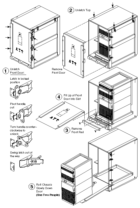
The following steps describe how to unpack a rackmount system, illustrated in Figure 3-1. Note that a minimum of two people are required to safely remove a rackmount system from the packing crate:
Release the six latches securing the door to the crate and remove the door.
Loosen the four latches securing the top of the crate.
Remove the two wing nuts securing the front rail and remove the rail from the crate.
Position the lip (located at the top of the door) in the slot immediately in front of the system platform.

Note: When positioning the door, ensure that the foam padding does not swing down and prevent the bottom edge of the door from evenly contacting the floor. Using two people, roll the system out of the crate and down the front door.
Warning: Use extreme caution when rolling the system chassis down the door. The weight and dimensions of the system make it difficult to control. Personal injury and system damage could result if the chassis becomes unbalanced or builds too much momentum coming down the ramp.
At least two people are required to roll the system out of the crate.
Remove the documentation and accessories cartons.
Check the items received against the packing list.
Inspect each item for defects. Check for scratches, dents, rust, soiling, and loose or missing parts.
Open the cabinet and visually verify that the system is configured according to the shipping list.
The Challenge/Onyx rackmount system is configured by the factory to reflect a specific order; however, changes in the order, additional customer-requested options, or upgrades may require some field installation. The following sections describe how to access the cardcages, SCSI drive boxes, and power supply enclosure.
| Note: Dedicated cardcage slots and restrictions on board placement are found in Section 3.5.1.3, "Onyx Slot Assignments" and Section 3.5.1.4, "Challenge Slot Assignments." All three of the access covers to the chassis are held shut with magnetic strips; there are no latches. |
Gain access to the system cardcages by performing the following steps:
Open the upper front door of the chassis.
Release the quarter-turn captive screw, on the right side of the system status panel, and swing the panel out of the way (see Figure 3-2).
Release the two quarter-turn fasteners securing the I/O panel and lower the panel until it is almost horizontal.
Unlatch the cable supporting the I/O panel and gently allow the panel to pivot down toward the floor. Circuit boards may now be installed in or removed from the cardcage.
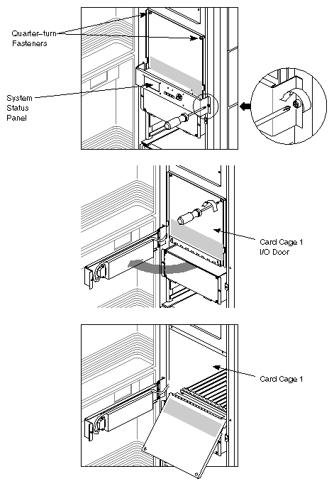
When the circuit board(s) are in place, reverse the preceding steps.
| Note: Observe proper ESD procedures when handling the boards. Ensure that the boards are correctly seated in the backplane or midplane connectors and that the ejector tabs have engaged the top and bottom card guides. |
Open the rear door of the system cabinet.
Determine if any of the cables attached to the I/O panel will obstruct the panel's movement when opened. Remove cables as required.
Release the two quarter-turn fasteners securing the I/O panel (see Figure 3-3) and lower the panel until it is horizontal.
Remove any internal I/O cables that will prevent the panel from pivoting down past horizontal.
Unlatch the cable supporting the I/O panel and gently allow the panel to pivot down toward the floor. Circuit boards may now be installed in or removed from the cardcage.
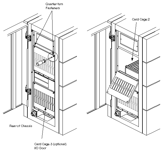
When the circuit board(s) are in place, reverse the preceding steps.
| Note: Observe proper ESD procedures when handling the boards. Ensure that the boards are correctly seated in the backplane or midplane connectors and that the ejector tabs have engaged the top and bottom card guides. |
The slot assignments for Onyx systems are shown in Figure 3-4 through Figure 3-6. Be aware that in the field the recommended slot assignments may be different (as indicated by the stick-on labels over the cardcages).
In Cardcage 1, the only board with a dedicated slot is the System Controller board. This restriction is due to the System Controller board's unique backplane connectors. There are no restrictions on any of the Ebus slots; CPUs and memory boards can be installed in any order.
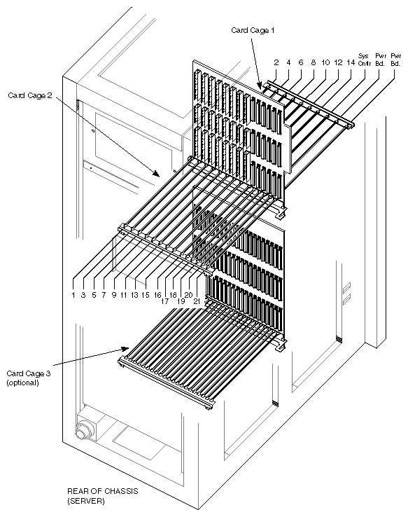
In Cardcage 2, the only Ebus board having a dedicated slot is the master IO4 board. The first (or only) IO4 board must be installed in slot 11, with its mounted VCAM attached to the slot 12 backplane connectors. Additional IO4s (with no VCAMs) can be installed sequentially in slots 9 (second IO4), 7 (third IO4), and 5 (fourth IO4). However, the graphics board set must be installed exactly as shown in the supporting figures.
| Note: The Ebus slots on both sides of the midplane are numbered from 1 to 11. Only the even-numbered slots in Cardcage 1 (the upper, front cardcage) have connectors. Cardcage 2 (the upper, rear cardcage) has connectors in only the odd-numbered slots. See Appendix F for a complete listing of all of the board fault LED error messages. |
In Cardcage 3, the boards must be installed exactly as shown in Figure 3-6. For more information on configuring Cardcage 3, including how to create multiple graphics pipes, see Section 3.11.5.2, "Onyx Graphics System Configuration."
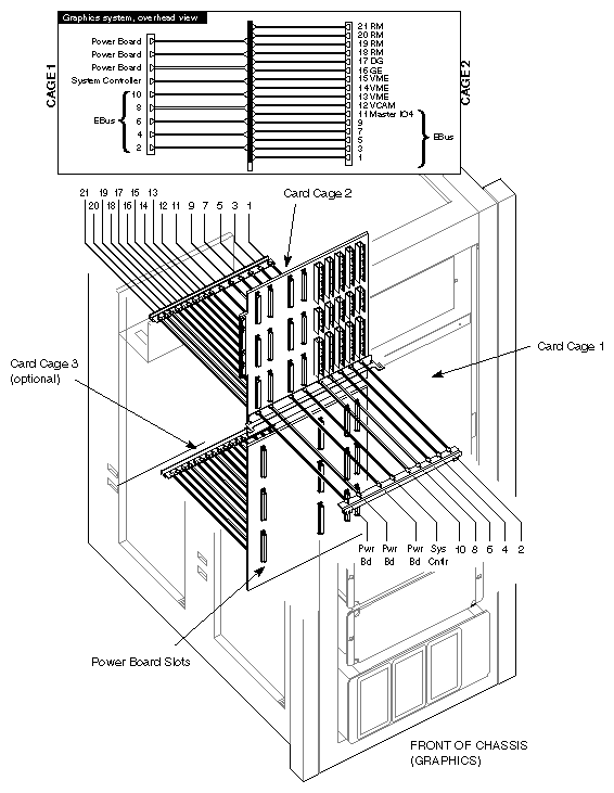
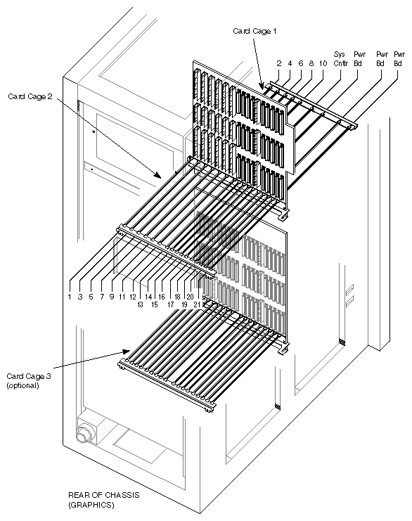
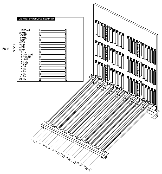
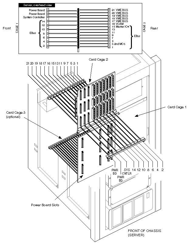
The slot assignments for Challenge systems are shown in Figure 3-7 through Figure 3-9. Be aware that in the field the recommended slot assignments may be different (as indicated by the stick-on labels over the cardcages).
In Cardcage 1, the only board with a dedicated slot is the System Controller power board. This restriction is due to the System Controller's unique backplane connectors. There are no restrictions on any of the Ebus slots; CPUs and memory boards can be installed in any order. (Note that by convention certain of these boards are typically installed in certain Ebus slots. See Figure 3-7.)
In Cardcage 2, the only Ebus board having a dedicated slot is the master IO4 board. The first (or only) IO4 board must be installed in slot 15, with its mounted VCAM attached to the slot 16 backplane connectors. Additional IO4s (with no VCAMs) must be installed sequentially in slots 13 (second IO4), 11 (third IO4), and 9 (fourth IO4).
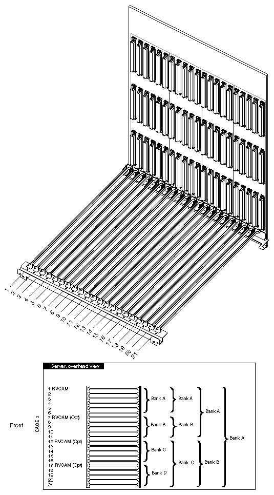
In Cardcage 3, the first (or only) Remote VCAM (RVCAM) must be installed in slot 1. Additional Remote VCAMs can be installed in slots 7, 12, and 17. Each RVCAM controls a separate VMEbus. Because of power limitations, you may have to install multiple RVCAM boards in order to drive the desired number of VMEbus boards. There can be one, two, three or four VMEbuses in Cardcage 3. Table 3-1 shows where to place the RVCAM boards for specific VMEbus configurations:
Table 3-1. Cardcage 3 Remote VCAM (RVCAM) Slot Assignments
Number of VMEbuses in Cardcage 3 | Cardcage 3 Slot in Which to Place RVCAM Board |
|---|---|
1 | 1 |
2 | 1 and 12 |
3 | 1, 7, and 12 |
4 | 1, 7, 12, and 17 |
Refer to Section 3.11.5.3, "Challenge Server System Configuration," for detailed procedures describing the Cardcage 3 configuration, including power limitations and cabling.
| Note: The VMEbus jumpering scheme is now the exact opposite as it was in older Silicon Graphics systems. Please read the following section carefully. |
Use jumpers on the VMEbus to skip over empty VME slots in Cardcage 2. If there are any empty slots on the midplane between the installed VMEbus boards, those slots must have jumpers installed to allow signals to pass through to the next occupied slot.
This applies only to the four middle card slots (slots 17 through 20). The first VME slot (16) always contains the VCAM, and the last VME slot (21) has no place to pass the bus signals to.
Each of the four middle slots has a corresponding jumper bank consisting of five jumpers. To jumper a bank, you install five individual jumpers in the bank. These jumpers are located on the Cardcage 1 side of the midplane, between the power bus slots (see Figure 3-10).
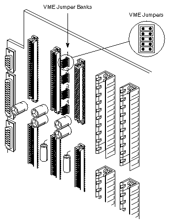
| Note: The optional Cardcage 3 VMEbus backplane does not have jumper banks as the midplane does. Empty VMEbus slots in Cardcage 3 are jumpered from the cardcage side. See Section 3.11, "Optional Third Cardcage (Cardcage 3) and Power Supply Tray," for the Cardcage 3 configuration instructions. |
The jumper banks correspond to the VME slots as shown in Table 3-2.
Table 3-2. Correspondence of VME Jumpers to VME Slots
Jumper Bank | Cardcage 2 VME Slot |
|---|---|
1 | 17 |
2 | 18 |
3 | 19 |
4 | 20 |
To jumper a bank, connect all of the five pairs of posts with jumpers.
For example, if you have VME boards in slots 18 and 20, you would place five jumpers in bank 1 (to pass signals through the vacant slot 17) and five jumpers in bank 3 (to pass signals through the vacant slot 19). Figure 3-11 illustrates this example.
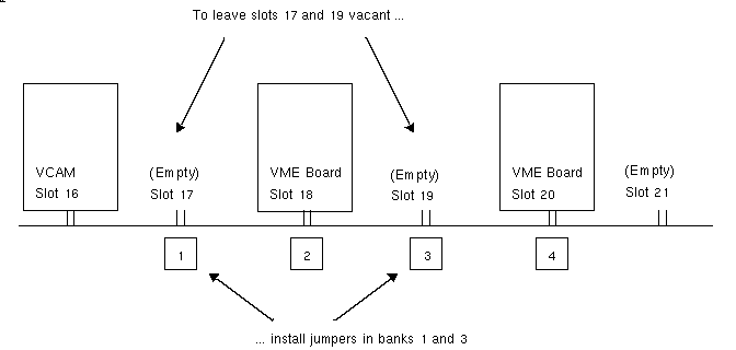
You only have to jumper the VME slots if you are leaving gaps between the VCAM in slot 16 and any VME boards, or if you are skipping slots between VME boards. If you have no VME boards installed in Cardcage 2, you do not need to install any jumpers.
| Note: The IP19 SIMMs and power jumpers are not field-replaceable. The information supplied in this section is intended as an aid in identifying the configuration of a specific board. |
The IP19 board is shipped with either 3.3V or 5.0V ICs and SIMMs. There are 32 power jumpers soldered to the board that are configured to match the IC power requirements. Each jumper is composed of three through-board mounting pads with "5V" silkscreened near one of the end holes. Jumpering the center hole to the end labeled 5V configures the board for 5-volt ICs. Jumpering the center hole to the unlabeled end hole configures the board for 3.3-volt ICs.
| Note: Observe proper ESD procedures when handling the boards and the SIMMs. Ensure that the boards are correctly seated in the midplane connectors and that the ejector tabs have engaged the top and bottom card guides. |
This section describes how memory is arranged and how to install SIMMs on the MC3 board.
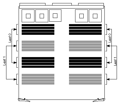
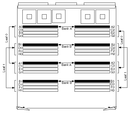
The MC3 memory board is composed of two leaves, leaf 0 and leaf 1 (see Figure 3-12). Each leaf contains 16 SIMM sockets.
The 16 SIMMs in leaf 0 are black and the 16 SIMMs in leaf 1 are gray. Note that each leaf consists of an upper and lower group of 8 SIMMs. Note also how the SIMM groups alternate between leaf 0 and leaf 1, up and down the board. This illustrates how memory is physically interleaved on the MC3 board.
The SIMMs on each leaf are organized into banks of memory. A bank is the basic memory building block. Each leaf is composed of four banks and there are eight banks per board. Banks A, C, E, and G make up leaf 0 and banks B, D, F, and H make up leaf 1 (see Figure 3-13). A single memory bank contains four SIMMs that are numbered 0 through 3 on the board. For example, the bank A SIMMs are identified as A0, A1, A2, and A3.
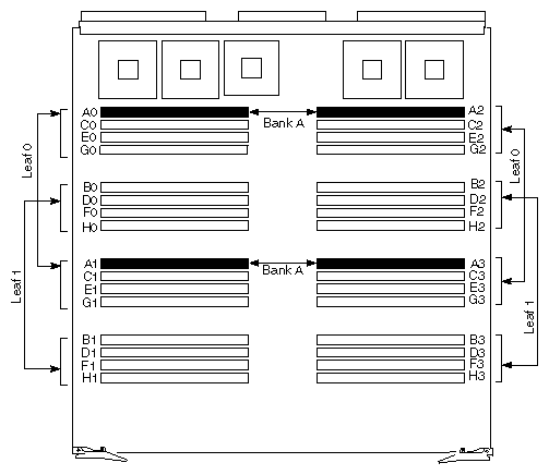
| Note: All SIMMs in a bank must be of the same type, that is, 16 or 64 MB. During power-up diagnostics, the memory tests check only one of the four SIMMs in a given location. If you mix SIMM types, memory errors will occur. On early MC3 boards, only the first two banks of each leaf can be populated. These boards are compatible with later boards that can populate all of their SIMM slots. Both boards can use the same SIMMs; the only difference between the boards is that the maximum configuration of the older boards is exactly half that of the later MC3s. |
| Caution: Observe proper ESD practices (such as using a ground strap and an antistatic mat) when installing SIMMs. |
Installing SIMMs
Install the SIMMs as follows:
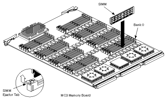
Slide each SIMM module directly into a single SIMM location with the notch at the ejector tab end (see Figure 3-14).
Install the SIMMs, a bank at a time; for example A0, A1, A2, and A3.
Removing SIMMs
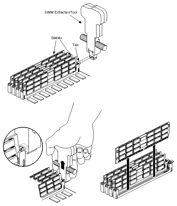
Use the SIMM extraction tool and the following instructions to remove SIMMs from the MC3 board.
| Note: Observe proper ESD procedures when handling the boards and the SIMMs. Ensure that the boards are correctly seated in the backplane connectors and that the ejector tabs have engaged the top and bottom card guides. |
Place the extraction tool over the SIMM ejector tab as shown in Figure 3-15.
Grasp the SIMM extraction tool and lift up the two stirrups on each side of the tool with your fingers.
Carefully remove each SIMM and set it aside.
SIMM Types
Both versions of the MC3 board can use two types of SIMM:
16 MB (high density)
64 MB (very high density)
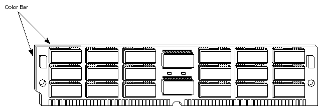
Table 3-3 provides additional information for these modules. Figure 3-16 shows an illustration of a SIMM.
Table 3-3. Challenge/Onyx System SIMM Information Chart
SIMM Size | SIMM Type | Color | Part Number |
|---|---|---|---|
16 MB | High Density | Pink | 030-0256-xxx |
64 MB | Very High Density | Purple | 030-0257-xxx |
| Note: The SIMMs are color-coded to distinguish type and size. The color bar appears on the top corner and side of the SIMM nearer the notched bottom corner. |
Interleaving Memory
Interleaving enables greater utilization of bus bandwidth by evenly distributing requests across the leaves and masking read latency. This results in significant read and write access improvement. The following compares the average bus bandwidth utilization during a read operation for different interleave factors:
one-way interleaving (50 percent)
two-way interleaving (66 percent)
four-way interleaving (80 percent)
eight-way interleaving (89 percent)
The Challenge/Onyx rackmount system supports one-, two-, four-, and eight-way interleaving. At boot-up, the CPU PROM monitor scans the SIMM configuration on the MC3(s) to determine the system's interleave factor.
One-way Interleaving
One-way interleaving is achieved using four SIMMs across a single bank of memory on a single MC3 board. One-way interleaving provides the lowest interleave factor and the least effective memory performance. See Figure 3-17 for an illustration of this configuration.
Two-way Interleaving
Two-way interleaving occurs across a single MC3 board, as a bank of memory on leaf 0 links with a bank of memory on leaf 1. Two-way interleaving requires a minimum of 8 SIMMs. To enable two-way interleaving, you must install the same SIMM type across corresponding banks in each leaf, for example, banks A and B. See Figure 3-18 for an illustration of this setup. See Table 3-4 for a list of corresponding banks.
| Note: To set up two-way interleaving, install the same SIMM type (for example, 16 MB) across corresponding banks in each leaf. |
Four-way Interleaving
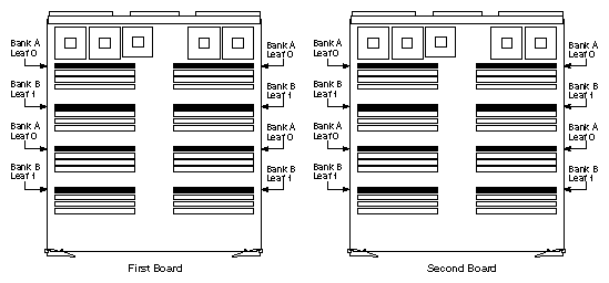
To enable four-way interleaving, you must first have two MC3 boards. Install the same SIMM type (for example, 16 MB) across corresponding banks (for example, banks A and B) on each MC3 board. Four-way interleaving requires a minimum of 16 SIMMs. See Figure 3-19 for an example of four-way interleaving.
Eight-way Interleaving
The Challenge/Onyx rackmount system can achieve eight-way interleaving using four MC3 boards. To set this up, you must install the same SIMM type across corresponding banks on each leaf on all four boards. Eight-way interleaving requires a minimum of 32 SIMMs.
Avoiding Three MC3 Board Configurations
Do not install three MC3 boards into a system, because this is not a very cost-effective configuration. Use only one-, two-, or four-MC3-board configurations, as applicable to the system.
A three-MC3 board setup is not desirable for the following reasons:
A three-MC3-board setup is available in only two memory configurations.
The memory upgrade path is severely limited.
Adding a third MC3 to an existing two-MC3 board (four-way interleaving) configuration can seriously affect the system's memory performance, depending upon how you are able to populate the memory boards. If you can fully populate all 16 banks of the first two boards, then populate either four or eight banks on the third MC3 board, you can remain at four-way interleaving. However, if you cannot configure the MC3 boards in this way, the interleave factor changes from four-way to either one- or two-way (depending on how the third MC3 board is set up). The system defaults to the lowest common interleave factor across the MC3 boards at boot-up time.
Number of CPUs
The more CPUs a system contains, the higher the interleave factor and number of memory boards that a system can properly support.
Table 3-5 provides guidelines for the recommended interleave factor, and the number of MC3s to use, based on the number of CPUs in a system.
Table 3-5. Recommended CPU-to-Interleave Factor Guidelines
Number of Recommended CPUs | Interleave Factor and Number of MC3 Boards to Achieve Standard Memory Performance | interleave Factor and Number of MC3 Boards to Achieve Higher Performance |
|---|---|---|
2 (using 1 CPU board) | 1-way (1 MC3 board) | 2-way (1 MC3 board) |
4 to 6 (using 1 to 2 CPU boards) | 2-way (1 MC3 board) | 2-way (1 MC3 board) |
8 to 10 (using 2 to 3 CPU boards) | 2-way (1 MC3 board) | 4-way (2 MC3 boards) |
12 to 14 (using 3 to 4 CPU boards) | 2-way (1 MC3 board) | 4-way (2 MC3 boards) |
16 to 18 (using 4 to 5 CPU boards) | 4-way (2 MC3 boards) | 8-way (4 MC3 boards) |
20 (using 5 CPU boards) | 4-way (2 MC3 boards) | 8-way (4 MC3 boards) |
22 to 36 (using 6 to 9 CPU boards) | 8-way (4 MC3 boards) | 8-way (4 MC3 boards) |
| Note: This table provides recommended (not required) memory guidelines. For example, a server system containing one CPU board can support a two-MC3-board configuration. However, a system containing three CPU boards will support this configuration more effectively. The higher the number of CPU boards, the more MC3 boards that a system can effectively support, and the better the overall system memory performance. |
Table 3-6 lists the mezzanine boards and the supported configurations. Note that the only restrictions on the available configurations are that the VCAM must be installed on the first (or only) IO4 board, and a standard F Mezz board will not physically fit on an IO4 board that already has a VCAM mounted.
Table 3-6. Supported Mezzanine Board Configurations
Host Board | VCAM | SMEZZ (SCSI-I) | SMEZZ (SCSI-II) | F Mezz | F Mezz (short) |
|---|---|---|---|---|---|
IO4 (first or only) | YES (required) | YES | YES | NO | YES (2) |
IO4 (additional) | NO | YES | YES | YES (2) | YES (2) |
VCAM
The VCAM mounts on the first IO4 board and is attached to VMEbus connectors on the midplane. In graphics systems, the first IO4 board is installed in slot 11 because it is the last Ebus slot in the cardcage and immediately adjacent to the first VMEbus slot. In server systems, the first IO4 board is installed in slot 15 for the same reason. See Figure 3-4 through Figure 3-6 for graphics cardcage slot assignments, and Figure 3-7 through Figure 3-9 for server cardcage slot assignments.
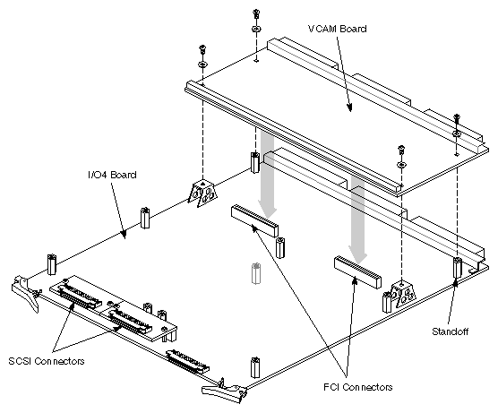
Attach the VCAM to the IO4 board with the three standoffs and screws provided (see Figure 3-20). Ensure that the FCI connectors from the IO4 board correctly mate with the VCAM connectors.
Install the boards in the cardcage as a single assembly, ensuring that both the Ebus connectors on the IO4 board and the VMEbus connectors on the VCAM are securely mated with the corresponding connectors on the midplane.
Mezzanine Boards
With the exception of the standard-length F Mezz, any combination of mezzanine boards may be installed on the IO4 board(s). Because of its greater length, the F Mezz board may only be mounted on IO4 boards that do not have a VCAM installed. Note that all of the interface modules mount to the IO4 board with four screws and standoffs (see Figure 3-21).
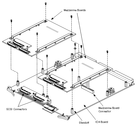
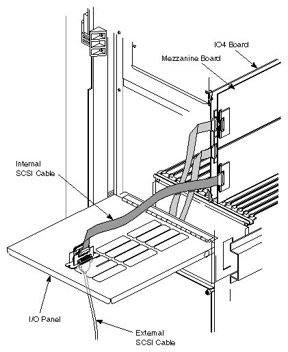
Figure 3-22 uses the SCSI mezzanine board to illustrate how the various mezzanine boards are cabled to the I/O panels.
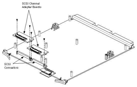
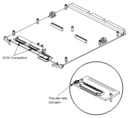
The SCSI channel adapter boards (differential and single-ended) are inserted directly into the SCSI connectors at the forward edge of the IO4 board. These boards convert the SCSI channel in which they are installed to either a differential or single-ended SCSI. The SCSI bus cables are then connected to the adapter boards (see Figure 3-23).
The single-ended adapter board has two transfer rate jumpers. These jumpers are installed or removed depending on whether or not the SCSI bus they are connected to is an internal or external bus. Install the jumpers if the bus supports only internal drives. This sets the SCSI bus data transfer rate at 10 MB per second. Remove the jumpers if the bus is connected to drives located outside the system cabinet. Removing the jumpers slows the bus down to 5 MB per second to allow for the greater distance the data must travel. See Section 2.4.3, "SCSI Channel Adapter Boards" and Appendix D, "Supplementary SCSI Information" for additional SCSI channel and drive configuration information.
| Note: The adapter modules are color-coded-the differential adapter is red, the single-ended adapter is green. |
The IO4 board has three replaceable 2A fuses located near the SCSI channel connectors. The two upper fuses provide power to the SCSI bus terminators. The lower fuse protects the Ethernet, RS-232, and keyboard/mouse ports.
| Warning: Connecting the Ethernet port to a transceiver box while the system is powered up can generate a voltage spike that will blow the lower fuse. Power down the system before connecting it to the Ethernet. |
The fuses are held in their respective sockets by friction. Pull them straight out to check or replace them.
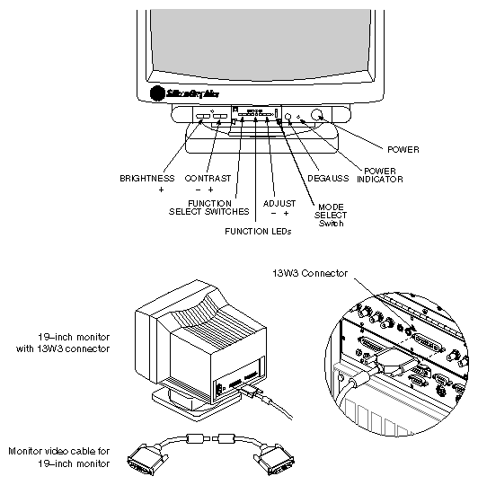
The Everest graphics workstation is shipped with one of two color monitors: the 21-inch (1600 x 1200 pixel) monitor is shipped with the RealityEngine2 graphics board set, and the 19-inch (1280 x 1024 pixel) monitor is shipped with the VTX graphics board set. Refer to Appendix C, "Connectors and Cables" to select the correct monitor cable for the specific installation.
The 21-inch Hitachi color monitor has 7 factory-preset viewing modes (screen geometry settings) and memory for an additional 23 customer-configured settings. The monitor controls are described in Table 3-7 and Table 3-8, and the preset viewing modes are listed in Table 3-9. The monitor cabling and the physical locations of the controls are shown in Figure 3-24.
Table 3-7. 21-inch Monitor Controls
Control | Description |
|---|---|
Power switch | Press on/press off switch. When power is on, the green LED in the switch is lit. |
Contrast control (half moon icon) | Turn to adjust foreground brightness. |
Brightness control (sun icon) | Turn to adjust background brightness. |
Degaussing switch | Press to manually degauss monitor (monitor will automatically degauss following power-on). |
Signal Input Selection switch | Selects BNC or 15-pin mini-D connectors. |
Manual/Auto Selection switch | Manual position allows display size and position to be changed using the Store, Selection, and Adjustment controls. The Auto position selects one of the 7 factory-preset viewing modes. |
Store switch | With the Manual/Auto Selection switch in the Auto position, pressing this switch steps through the preset viewing modes. With the Manual/Auto Selection switch in the Manual position, pressing this switch stores the displayed viewing mode. This mode is indicated when one of the adjustment LEDs lights. |
Selection switch | With the Manual/Auto Selection switch in the Manual position, pressing this switch steps through the 4 available adjustments (horizontal size, horizontal position, vertical size, vertical position). When the adjustment is active, the corresponding amber LED is lit. |
Adjustment switch (–) | Pressing this switch, with either the horizontal or vertical size adjustment selected, decreases screen size. With the horizontal position adjustment selected, pressing this switch shifts the screen position to the left. With the vertical position adjustment selected, pressing this switch shifts the screen down. |
Adjustment switch (+) | Pressing this switch, with either the horizontal or vertical size adjustment selected, increases screen size. With the horizontal position adjustment selected, pressing this switch shifts the screen position to the right. With the vertical position adjustment selected, pressing this switch shifts the screen up. |
Video Signal Termination switches (3) (located on rear panel) | Press in when installing a single monitor (provides 75-ohm termination). Release switches when connecting multiple monitors with loop-through (provides higher impedance). |
Sync Adjustment switch (located on rear panel) | Release the switch to manually adjust the incoming sync signal. |
Table 3-8. Viewing Mode Adjustments
Active (Lit) Adjustment Switch | Minus (–) | Plus (+) |
|---|---|---|
Horizontal Size | decrease | increase |
Horizontal Position | shift left | shift right |
Vertical Size | decrease | increase |
Vertical Position | shift down | shift up |
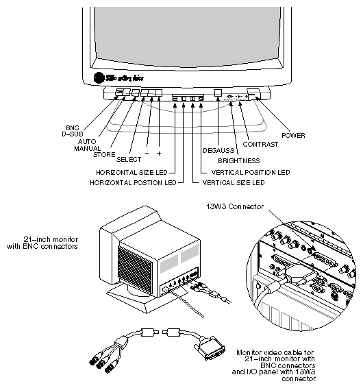
Table 3-9. Preset Viewing Modes for 21-inch Monitor
| Video Mode | Horizontal Frequency | Vertical | Resolution |
|---|---|---|---|---|
1 | VGA350 | 31.5 kHz | 70 Hz | 640 x 350 |
2 | VGA400 | 31.5 kHz | 70 Hz | 640 x 400 |
3 | VGA480 | 31.5 kHz | 60 Hz | 640 x 480 |
4 | 8514/A | 35.5 kHz | 87 Hz | 1024 x 768 (interlaced) |
5 | 1024 x 768 | 48.8 kHz | 60 Hz | 1024 x 768 |
6 | 1152 x 870 | 63.5 kHz | 70 Hz | 1152 x 870 |
7 | 1152 x 870 | 68.7 kHz | 75 Hz | 1152 x 870 |
Manually Adjusting the Vertical Sync
The following procedure is used to adjust the monitor's screen geometry when the monitor is experiencing problems with the vertical sync.
| Note: Do not use this switch unless there is a problem with the incoming sync signal. |
Select the "Manual" mode by pushing in the Auto/Manual Selection switch.
Push out the Sync Adjustment switch (located at the rear of the monitor).
If the monitor is out of sync, or there is no display with the correct input signal, press the "+" adjustment switch repeatedly until the displayed image is correct.
Note: Both the adjustment switches change the screen geometry in single increments. Each time a switch is pressed, the screen geometry is changed by one increment. Holding a switch in will not cause a continuous change in the screen geometry. When the screen geometry is correct, press the adjustment switch one more time.
If the monitor displays partial skew (the top of the screen appears to tear to the right), press the "–" adjustment switch repeatedly until the displayed image is correct.
When the vertical sync is correct, push in the Sync Adjustment switch to the off position.
If the size and position of the displayed image is incorrect, use the Selection switch to activate the required adjustment (the corresponding LED will light), and the "+" and "–" adjustment switches to correct the screen geometry.
Press the Store switch to save the adjustments in the monitor's memory.
Push out the Auto/Manual Selection switch to return to "Auto" mode.
The 19-inch Mitsubishi color monitor has four factory-preset viewing modes (screen geometry settings) and memory for eight additional customer-configured settings.
The monitor controls are described in Table 3-10, and the preset viewing modes are listed in Table 3-11. The monitor cabling and the physical locations of the controls are shown in Figure 3-25.
Table 3-10. 19-inch Monitor Controls
Control | Description |
|---|---|
Power switch | Press on/press off switch. When power is on, the green LED to the left of the switch is lit. |
Contrast control (half moon icon) | Two switches (+ and –) used to adjust foreground brightness. An LED, located between the Contrast and Brightness controls, lights when the control is active. The LED flashes when the control limit is reached. |
Brightness control (sun icon) | Two switches (+ and –) used to adjust background brightness. An LED, located between the Contrast and Brightness controls, lights when the control is active. The LED flashes when the control limit is reached. |
Degaussing switch | Press to manually degauss monitor (monitor will automatically degauss following power-on). |
The following controls are located behind the panel that is between the Degauss and Contrast controls |
|
Select switches | These two controls allow you to select any one of the four user-adjustable functions. The LED below each function icon lights to indicate that the function is active. The LED between the Contrast and Brightness controls flashes when the control limit is reached. |
Function icons | These icons represent the adjustable screen parameters: horizontal position, horizontal size, vertical position, and vertical size. |
Adjust switches (+ and -) | Press these switches to modify the selected function. Your adjustments are automatically saved in memory. |
Memory Recall switch | Press this switch to restore all of the factory-preset viewing modes. |
Mode Select switch | This switch has three positions: 1 -3. Position 1 selects the four preset viewing modes. Positions 2 and 3 each provide four memory locations for user-defined viewing modes.
For normal operation with the VTX board set, leave the switch in position 1. If you decide to modify a viewing mode, select position 2 or 3 so that you do not overwrite the preset modes. |
Table 3-11. Preset Viewing Modes for 19-inch Monitor
| Resolution | Horizontal Frequency | Vertical Frequency |
|---|---|---|---|
1 | 1024 x 768 | 48.5 kHz | 59.6 Hz |
2 | 1280 x 1024 | 63.9 kHz | 60 Hz |
3 | 1280 x 492 | 63.9 kHz | 119.88 Hz |
4 | 1280 x 1024 | 76.9 kHz | 72.3 Hz |
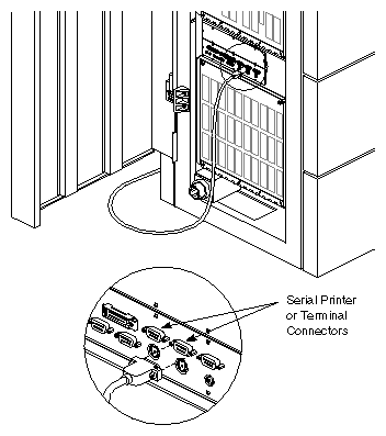
The Challenge server is shipped with an ASCII terminal. The terminal is connected to the system using a null modem cable with a 9-pin D connector at one end and a 25-pin D connector at the other. Refer to the pin assignments in Table 3-12 if a different cable/connector assembly is being used. Attach the terminal as shown in Figure 3-26.
| Note: Configure the terminal for 9600 baud, eight bits, no parity, and one stop bit. |
Table 3-12. ASCII Terminal Connection Pin Assignments
25-pin (DB-25) Connector | 9-pin (DB-9) Connector | Signal Description |
|---|---|---|
2 | 3 | Received Data (RXD) |
3 | 2 | Transmitted Data (TXD) |
7 | 7 | Signal Ground (GND) |
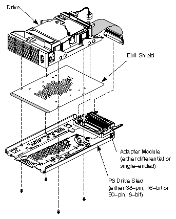
| Warning: If you install the EMI shield upside down in a P8 drive sled, there is a high risk of an electrical short in the drive. The EMI shield is copper and is coated on one side with clear plastic insulation. The insulated side of the shield must be placed against the drive. |
The SCSIBox accepts any SCSI storage drive that is configured as a Front Loading Device (FLD). A drive configured as an FLD is mounted on a P8 drive sled. The drive sled adapts the drive's signal and power connectors to those on the SCSIBox backplane. Figure 3-27 shows the components of the drive sled. See Section 1.5, "Front-loading Devices" for more information on drive sled components and shielding.
| Note: There are two versions of P8 drive sled. The P8-SLED-8 is a 50-pin, 8-bit sled. The P8-SLED-16 is a 68-pin, 16-bit sled. |
The interface between the SCSI device and the backplane is provided by an adapter module that snaps into place at the rear of the drive sled (see Figure 3-27). The adapter module is available in two versions: single-ended and differential. Both versions of the adapter provide two bus connectors, allowing either of the two internal buses in the SCSIBox to be selected. Depending on the drive type, the SCSI drive cable can be either 50- or 68-pin. When a 50-pin cable from a drive is connected to the corresponding adapter module, the signals are reassigned and output to the SCSIBox backplane through a 68-pin connector. When a 68-pin cable is connected to a differential adapter module, the signals are simply passed through the 68-pin connector to the SCSIBox backplane.
The sled and attached drive are inserted into corresponding drive trays mounted in the SCSIBox. The trays position the drive sleds so that their connectors are correctly aligned with the backplane connectors. A locking lever on the sled secures the FLD in place.
Refer to the CHALLENGE™/Onyx™Peripherals Guide (document number 108-7048-010) for detailed information about the supported drives, including jumper settings for specific drives.
| Note: This guide was formerly the Peripherals Reference Guide and Man Pages. |
The Everest systems support five SCSI channel configurations:
8-bit differential
16-bit differential
8-bit single-ended (slow)
8-bit single-ended (fast)
16-bit single-ended
Each installed drive must be configured to match the characteristics of the channel to which it is attached. The channel characteristics must be consistent, beginning with the SCSI port and ending with the drive itself. Figure 3-28 is a diagram representing a typical SCSI channel. The various decision points at which the channel must be configured are called out and explained in the notes that follow.
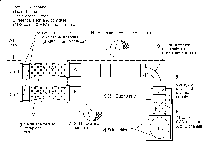
To install a SCSI device on a specific channel, perform the following steps while referring to Figure 3-28 (the numerals in bold represent steps in the procedure where the hardware has to be selected and then installed, or configured):
Configure the channels at the IO4 board by inserting the appropriate SCSI channel adapter board into each of the two 100-pin connectors on the IO4 board (refer to Figure 3-23). The standard configuration for SCSIBoxes has channel A configured for differential operation and channel B configured for single-ended operation.
Each channel must be configured at both the IO4 board and at the SCSIBox backplane.
Note: The channel adapter boards used on the IO4 are also used on the SCSI mezzanine cards. The adapter boards are color-coded: the single-ended adapter (P/N 034-0355-00x) is green, the differential adapter (P/N 034-0354-00x) is red. Set the transfer rate of the channels on the channel adapter boards. The green, single-ended SCSI channel adapter board has two transfer-rate jumpers. If the channel being configured is an internal channel (for example the SCSIBox), leave the jumpers installed, and the bus transfer rate will remain at 10 MB/second (or fast mode). If an external single-ended channel is being configured, remove both jumpers and the transfer rate drops to 5 MB/second (slow mode). There is no wrong way to install the jumpers; they require no special orientation. See Figure 3-29.
Cable the channel adapters to the backplane. Connect the IO4 SCSI channel 0 to SCSIBox channel A and the IO4 SCSI channel 1 to SCSIBox channel B.
Set the drive ID to a number that is not assigned to any other devices on that bus. The ranges are between 1 and 7 for single-ended drives, and between 1 and 15 for differential drives.
Note: The SCSI drive controller's ID is generally set to 0. This is in direct contrast with the Silicon Graphics VME based 4210/4220 SCSI controller boards. The 4210/4220 (Jaguar/Cougar) use 7 for the controller ID number. The cabling applications in this section are not intended for use with Jaguar/Cougar controllers.
Drive IDs cannot be changed while the drives are powered up.Configure the drive sled channel adapter to match the drive (either single-ended or differential) and snap it into place on the drive sled. The 2-GB disk drives supplied with the system are differential, the 1.2-GB drives are single-ended. To mount other devices, consult the manufacturer's documentation. See Figure 3-30 and Figure 3-31 for the channel adapter jumper settings.
Choose the SCSI channel that the drive will be attached to by inserting the free end of the drive's SCSI cable into either connector A or B, on the channel adapter. "A" corresponds to SCSIBox channel 0, "B" corresponds to SCSIBox channel 1.
Configure the SCSIBox by setting the SCSI backplane jumpers as shown in Figure 3-32.
If you are not going to continue the channel to another SCSIBox (differential channels only), you must terminate each channel with the proper termination plug on the rear of the SCSIBox backplane.
Caution: Use the correct channel terminator for each SCSI channel. Attempting to terminate a single-ended channel with a differential terminator, or a differential channel with a single-ended terminator can result in system malfunction and possible equipment damage. Insert the drive in the selected SCSIBox slot.
Note: See Appendix D, "Supplementary SCSI Information," for a more detailed explanation of this process.
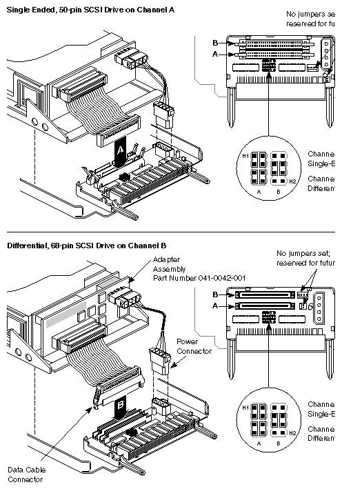
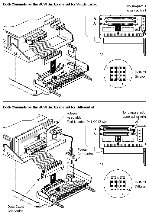
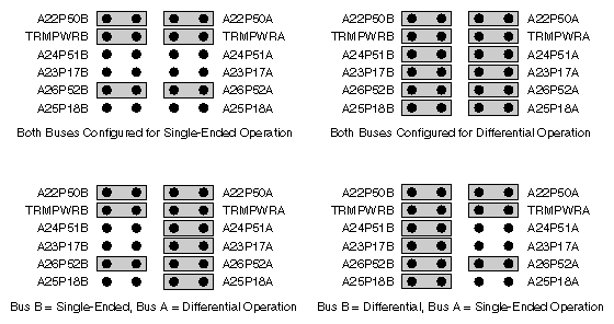
This section describes how to cable optional peripherals to the Challenge and Onyx rackmount systems. For a complete description of connector pin assignments, see Appendix C, "Connectors and Cables."
The SCSI channels supporting the internal drive boxes are terminated at the SCSIBox backplanes and at the IO4 board. Cable and terminate external SCSI channels as follows:
Power down the system as described in Section 3.8, "Bringing the System Up and Down."
Open the Cardcage 2 I/O panel as described in Section 3.5.1.2, "Accessing Cardcage 2 and Cardcage 3."
Locate the SCSI channel to which the drive(s) will be connected.
Install a SCSI cable between the connector on either the selected IO4 or mezzanine card, and a SCSI connector on the I/O panel as shown in Figure 3-33.
Close the I/O panel, ensuring that the internal cables are not pinched, kinked, or dislodged from the connectors.
Attach a SCSI cable of the correct length between the remote drive(s) and the I/O panel connector selected in step 4.
Ensure that the channel is correctly terminated at the last remote device.
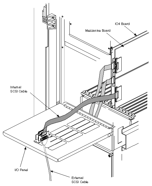
| Note: The maximum allowable length for single-ended (standard) SCSI cabling is 19.6 feet (6 meters). This maximum length reflects the combined lengths of both the internal and external cables. The maximum allowable cable length for differential SCSI is 80.02 feet (25 meters). If a single-ended SCSI channel is being routed to external drives, ensure that the transfer-rate jumpers are removed from the SCSI Channel Adapter board (refer to Section 3.5.1.9, "SCSI Channel Adapter Boards"). |
50-pin SCSI devices can be connected to the system's 68-pin SCSI ports using a Centronics adapter cable (SGI P/N 018-0347-001). This adapter cable is available in only one length and is intended to be used to temporarily connect a CD-ROM drive to the system when downloading the operating system. Use the adapter cable together with a standard 50-pin Centronics cable to connect external SCSI devices.
Ensure that the SCSI port(s) that the external devices are being attached to are correctly configured and terminated for the device type (refer to Section 3.6, "Storage Devices"). Also verify that the total combined length of the SCSI cables does not exceed the maximum allowable length for that particular channel type (single-ended or differential).
The printer connector can be any of the DB-9 serial ports on the main I/O panel. The pin assignments for the various connectors are shown in Table 3-13. Cable the printer as shown in Figure 3-34.
Table 3-13. Serial Printer/Terminal Connector Pin Assignments
25-pin (DB-25) Connector | 9-pin (DB-9) Connector | Signal Description |
|---|---|---|
2 | 3 | Received Data (RXD) |
3 | 2 | Transmitted Data (TXD) |
7 | 7 | Signal Ground (GND) |
For graphics systems, use the Print Manager menu to configure the software to recognize the printer. For servers, refer to the IRIX Advanced Site and Server Administration Guide for more information about printer configuration. For a complete description of serial port pin assignments, see Appendix C, "Connectors and Cables."
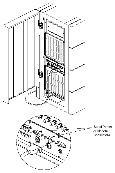
The modem connection can be to any of the DB-9 serial ports on the main I/O panel. The pin assignments for the various connectors are shown in Table 3-14. Cable the modem as shown in Figure 3-34.
Table 3-14. RS-232 Modem Connector Pin Assignments
25-pin (DB-25) Connector | 9-pin (DB-9) Connector | Signal Description |
|---|---|---|
2 | 2 | Transmitted Data (TXD) |
3 | 3 | Received Data (RXD) |
4 | 4 | Request to Send (RTS) |
5 | 5 | Clear to Send (CTS) |
8 | 8 | Data Carrier Detect (DCD) |
7 | 7 | Signal Ground (GND) |
20 | 9 | Data Terminal Ready (DTR) |
| Note: This product requires the use of external shielded cables in order to maintain compliance with Part 15 of the FCC rules. Serial cables from different vendors are not compatible. |
Refer to the IRIX Advanced Site and Server Administration Guide for more information about modem configuration. For a complete description of serial port pin assignments, see Appendix C, "Connectors and Cables."
To connect a parallel printer to the system, attach the printer cable to the 25-pin parallel connector on the main I/O panel (see Figure 3-35).
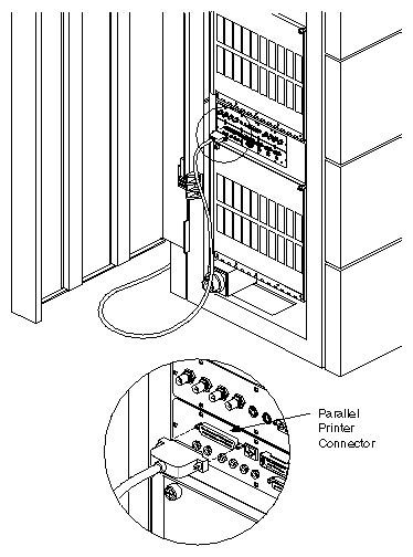
The pin assignments are shown in Table 3-15. Ensure that the pin assignments at the system's parallel port are properly matched to the pin assignments on the printer.
Table 3-15. Parallel Port Connector Pin Assignments
25-pin (DB-25) Connector | Signal Description |
|---|---|
1 | STB (Data Strobe) |
2 | DATA 0 |
3 | DATA 1 |
4 | DATA 2 |
5 | DATA 3 |
6 | DATA 4 |
7 | DATA 5 |
8 | DATA 6 |
9 | DATA 7 |
10 | DATA ACK |
11 | BUSY |
12 | PE (Paper Empty) |
13 | SLCT (Select) |
14 | AUTOFD (Autofeed) |
15 | ERROR |
For graphics systems, use the Print Manager menu to configure the software to recognize the printer. For servers, refer to the IRIX Advanced Site and Server Administration Guide for more information about printer configuration.
This section describes the procedures used to power the system up and down. For more information on the power-up, power-down, and boot processes, refer to the Challenge/Onyx Diagnostic Roadmap (P/N 108-7045-010).
| Warning: The Challenge/Onyx rackmount operates on 220-400VAC. Use extreme caution when working around this voltage. Never install or remove power cords without first turning off the equipment. |
There is 48VDC on the system midplane. This voltage is present even if the system has been reset or halted.
| Warning: Refer to the power requirements found in the CHALLENGE/Onyx Site Preparation Guide (P/N 108-7040-010) before applying power to the system. |
Bring up the system as follows:
Power up the system in the following order:
System cabinet
- Open the lower front door of the system cabinet.
- Turn on the main power switch, located near the lower right front corner of the cabinet.
- Turn the key switch to the On position.
Terminal or monitor
Printer (if installed)
| Note: All internal storage devices are automatically powered up by the System Controller. |
Monitor the system status panel to follow the progress of the boot arbitration process. Table 3-16 lists the possible boot messages (refer to Appendix E, "System Controller Error and Status Messages" for a complete listing of the System Controller error and status messages):
Table 3-16. Boot Status (Arbitration) Messages
Bootmaster CPU Selection Message
Context and Meaning of Message
BOOT ARBITRATION NOT STARTED
The system CPU board(s) have not begun the arbitration process.
BOOT ARBITRATION IN PROCESS
The System Controller is searching for the bootmaster CPU.
ARBITRATION COMPLETE BOARD OxZZ PROC OxZZ
The chosen boot master CPU has identified itself to the System Controller and communication is fully established.
BOOT ARBITRATION INCOMPLETE NO MASTER
An error has occurred in the boot process and no boot master CPU is communicating with the System Controller.
When the system start up menu appears, press <Esc> to enter the System Maintenance menu. Enter 5 to select "Enter Command Monitor."
Type hinv, then press <Enter> to display the system's hardware inventory.
Confirm that the displayed inventory matches the shipping list.
Quit the Command Monitor by typing Exit.
When the System Maintenance menu reappears, type 1 to select the "Start System" command. The system will come up and display the desktop.
| Warning: Allow power to drain five (5) minutes before starting any work on the backplane or midplane. Because of the number of capacitors throughout the power system, a significant voltage remains in the system immediately after you shut off the main power switch. |
Bring the system down as follows:
If the system is currently running normally, verify there are no users working on the system:
Log in as root.
At a shell prompt, use the IRIX who(1) command to see who is logged on to the system. If any other users are logged on, notify them that the system will be coming down and that they should log off. Refer to the IRIX Advanced Site and Server Administration Guide for a description of methods of notifying users of a system shutdown.
While still logged in as root, enter /etc/halt at a shell prompt. This command will gracefully shut down the system software and leave the system at the PROM monitor level.
Once you are at the PROM monitor, power down the system in the following order:
Terminal or monitor
Printer (if installed)
System cabinet
- Turn the key switch to the Off position.
- Open the lower front door of the system cabinet.
- Turn off the main power switch, located near the lower right front corner of the cabinet.
- If you are going to disassemble the system, for example to install an optional Cardcage 3, allow the power to drain for five (5) minutes before starting work.
| Note: All internal storage devices are automatically powered down by the System Controller. |
Refer to the Challenge/Onyx Diagnostic Roadmap for detailed explanations of the power-up sequence and the various system startup messages.
The basic operating system is installed on the system disk. Additional features and third-party software must be loaded using a tape drive or CD player. Refer to the IRIS Software Installation Guide for detailed information about installing Silicon Graphics software.
This section provides step-by-step instructions for the removal and replacement of all of the field-replaceable units (FRUs) in the Challenge and Onyx rackmount systems.
Table 3-17 lists all of the FRUs and their part numbers. Unless otherwise indicated, all components are common to both the Challenge and the Onyx rackmount systems.
Table 3-17. Rackmount System Field-Replaceable Units
Component Description | Part Number |
|---|---|
Boards |
|
IP19 CPU Board (2 CPU) | 030-0249-003 |
IP19 CPU Board (4 CPU) | 030-0250-003 |
MC3 Memory Board | 030-0245-006 |
IO4 Interface Board | 030-0240-009 |
SIMM (16MB) | 030-0256-001 |
SIMM (64MB) | 030-0257-001 |
505 Power Board | 030-0263-003 |
S Mezz Board (WD93) | 030-0312-001 |
System Controller Board | 030-0265-004 |
VMEbus Power Board | 030-0264-003 |
Cardcage 3 Power Board | 013-0620-001 |
Power Board Extender | 040-0520-001 |
505X2 Power Board | 013-0617-001 |
VCAM | 030-0243-005 |
SCSI Channel Adapter Module (single-ended) | 030-0305-002 |
SCSI Channel Adapter Module (differential) | 030-0304-002 |
First IO4 Assy (w/VCAM) | 013-0646-001 |
GE10V Geometry Engine Board (VTX graphics system) | 030-0363-002 |
GE10 Geometry Engine Board (RealityEngine2 graphics system) | 030-0325-002 |
DG2 Display Generator Board (Graphics system) | 030-0223-009 |
RM4 Raster Memory Board (Graphics system) | 030-0337-001 |
Chassis Components |
|
1900-Watt Off-Line Switcher (OLS) | 013-0513-002 |
OLS Power Shelf (1-2 OLSs) | 013-0549-002 |
System Controller Status Panel | 013-0539-001 |
SCSIBox Drive Box (w/o drives) | 013-0526-002 |
2-GB SCSI Drive | 041-0042-001 |
Rotary Fan Assy | 013-0538-002 |
Midplane (Graphics system) | 030-0254-002 |
Midplane (Server system) | 030-0253-006 |
Analog Video Cable | 018-0291-002 |
SCSI Cable Assy (IO4 to SCSIBox) | 018-0302-002 |
Status Panel Cable Assy | 018-0306-002 |
Blower Power Cable (External) | 018-0314-001 |
SCSI Cable Assy (External Control) | 018-0315-001 |
ChallengeVault Remote Control Cable | 018-0319-002 |
General I/O Cable Assy | 018-0333-001 |
Secondary I/O Cable Assy | 018-0331-001 |
Remove the doors on a rackmount system as follows:
Open the door part-way.
Lift the door off the hinge pins
Replace the doors in the opposite manner.
Remove the chassis side panels (skins) as follows:
Stand at the rear of the chassis on either the right or left side.
Brace the chassis with your foot so that it does not roll backwards when you pull on the chassis side panels.
There are a total of eight individual panels, four per side of the chassis. Starting with the top panel, grasp the panel with both hands through the access hole at the rear off the panel.
While keeping your foot braced against the bottom of the chassis, tug backwards sharply on the side panel. It should pull free. If it does not, tug slightly harder. Be careful not to tip the chassis.
Repeat this procedure for each of the eight panels (four per side of the chassis).
| Note: Be careful when handling the panels. Place them aside, out of your immediate work area. Be careful not to scratch or mar the panels. |

The video clip above illustrates how to remove a side panel. Note hand position when grasping the panel and the placement of the foot to brace the chassis.
Remove an OLS as follows:
Power down the system as described in Section 3.8, "Bringing the System Up and Down."
Allow power to drain from the system for five (5) minutes.
Open the lower front access door.
Remove the three screws securing the OLS to be removed (see Figure 3-36).
Grasp the OLS by the ring in the upper right corner, and remove it from the power supply enclosure.
Install an OLS by reversing the steps in this procedure. Ensure that the connector at the rear of the OLS mates correctly with the corresponding connector in the power supply enclosure.
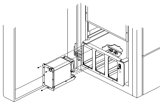
The following instructions describe how to remove the blower assembly:
Power down the system as described in Section 3.8, "Bringing the System Up and Down."
Wait a few moments for the blower fan to spin down before opening the blower access cover.
Warning: Do not work on or around the blower assembly if the fan is spinning and exposed. Always wait for the fan to stop spinning before opening the access cover. Loosen the two Phillips screws on the front of the blower access cover, then slide the access cover up and off of the screws. See Figure 3-37.
Unscrew the two captive thumbscrews that hold the blower assembly in place. You may have to use a flat-blade screwdriver to loosen them.
Slide the blower out of the system. There are no cables to disconnect; power to the blower is provided by a mating receptacle.
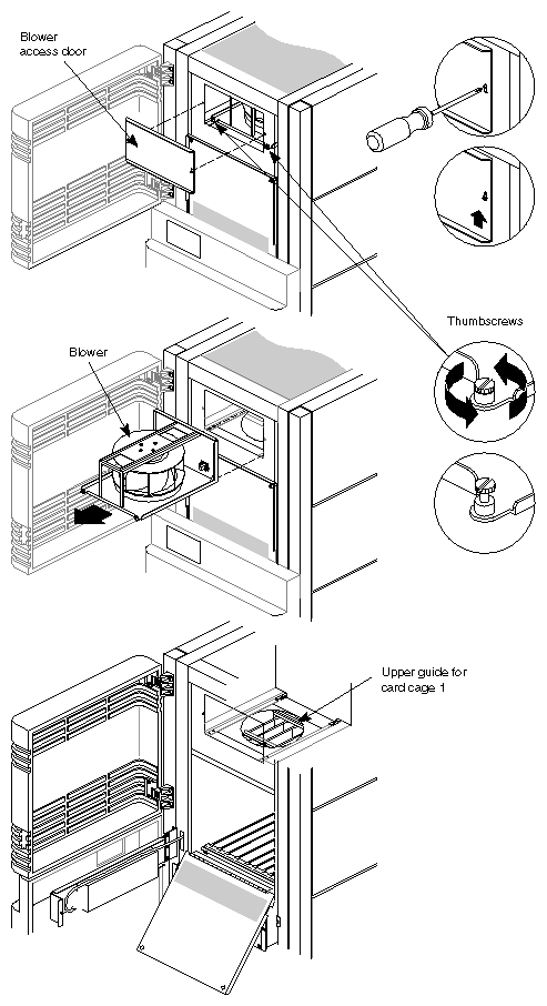
To install the blower assembly, reverse this procedure. When installing, tighten the captive thumbscrews with a flat-blade screwdriver.
Use the following instructions to install or remove the SCSIBox drive enclosures:
| Note: The optional SCSIBox is identical to the standard-equipment drive enclosure that is shipped with all rackmount systems, and is installed and removed in the same way. This optional box mounts in the enclosure directly below the existing SCSI drive box. |
Power down the system as described in Section 3.8, "Bringing the System Up and Down."
Allow power to drain from the system for five (5) minutes.
Unpack the SCSIBox and remove any drives (if installed).
Remove the side panels from the left side of the system chassis. See Section 3.10.2, "Chassis Doors and Side Panels (Skins)."
Note: Use care when handling the side panels. Store them in a safe place during this procedure to avoid scratching or marring them. Working from the left side of the system chassis, unfasten the nuts and screws securing the SCSI cable access port cover. Note that the lower right screw is also used to mount the lower inside blanking plate. Remove the blanking plate to provide a cable port for the second SCSIBox (see Figure 3-38).
Note: The blanking plate will fall to the bottom of the chassis when the right bottom screw is removed. Be prepared to catch it as you remove the screws that hold it in place.
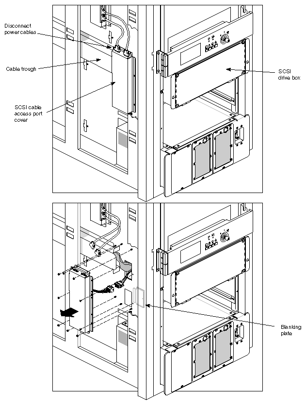
| Warning: When installing or removing a SCSIBox, be careful not to catch or cut any of the cables on the edges of the access port. |
Refer to Section 3.6, "Storage Devices," to verify that the SCSIBox backplane is correctly configured.
Slide the SCSIBox into the enclosure until the flange on either side of the box contacts the system chassis. Fasten the box in place with the spring-loaded quarter-turn screws mounted on the flanges (see Figure 3-39).
Locate the 2 SCSI cables and the power cable for the optional SCSIBox. These cables run down the left side of the system cabinet and exit from the cable routing box immediately to the rear of the SCSI cable access ports (see Figure 3-40).
Connect the power cable to the pigtail attached to the 512S power board.
Route the two unattached SCSI cables into the lower access port and connect them to the SCSIBox backplane.
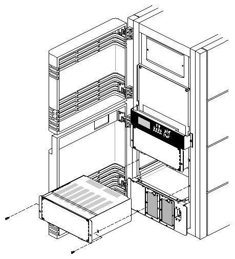
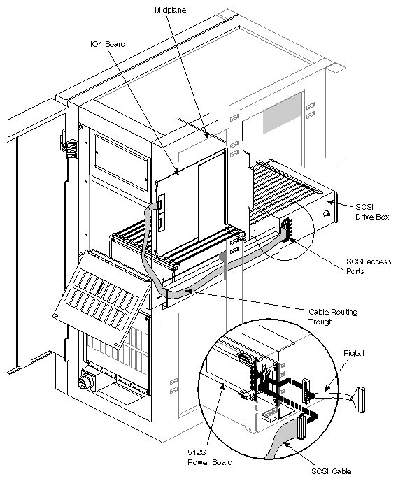
| Note: Verify that the bus designations on the cables match the designations on the corresponding SCSIBox connectors. |
Reinstall the SCSI cable access port cover (note that the lower screw that secured the inside blanking plate now threads directly into the side of the SCSIBox).
Reinstall the side panels.
Refer to Section 3.5.1.8, "VCAM and Mezzanine Board Installation," to install and cable a SCSI Interface Module.
Refer to Section 3.6, "Storage Devices," and verify that the system disk (boot disk) and any other drives to be installed are correctly configured. Install the drives in the SCSIBox.
Power up the system (refer to Section 3.8, "Bringing the System Up and Down").
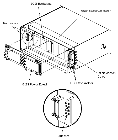
The 512S power board mounts to the rear of the backplane in the SCSIBox (see Figure 3-41). Remove or replace the 512S board as follows:
Remove the SCSIBox as described in Section 3.10.5, "SCSIBox."
Unfasten the four crosshead screws securing the rear cover to the SCSIBox.
Remove the 6 securing screws and lift the old power board off of the six standoffs and screw the new board onto the standoffs in its place. When installing the new 512S board, ensure that the connector on the back of the board mates with the connector on the backplane.
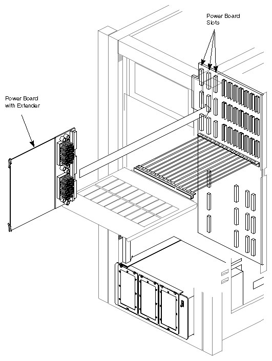
This procedure describes how to install power boards in Cardcage 1. Section 3.10.3, "Off-line Switchers" provides instructions for installing off-line switchers.
Power boards designed for use in Cardcage 1 are mounted on extenders and are installed exactly like any other board (see Figure 3-42). The slots designated for the power boards are shown in more detail in Figure 3-4 (graphics system) and Figure 3-7 (server). Note that the System Controller board has a combination of male and female connectors and must be installed in the slot to the immediate left of the left-most Ebus slot in Cardcage 1.
For information about installing power boards on the Cardcage 3 backplane in a graphics system, see Figure 3-58. For information about installing power boards on the Cardcage 3 backplane in a server system, see Figure 3-62.
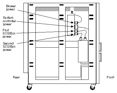
This procedure describes how to remove or replace the system midplane.
Power down the system as described in Section 3.8, "Bringing the System Up and Down."
Allow power to drain from the system for five (5) minutes.
Remove the side panels from both sides of the cabinet. See Section 3.10.2, "Chassis Doors and Side Panels (Skins)."
Working at the left side of the cabinet (as seen from the front of the system), unfasten the 3-4 cables attached to the midplane connectors (see Figure 3-43).
Gain access to both Cardcage 1 and 2 (see Section 3.5.1.1, "Accessing Cardcage 1" and Section 3.5.1.2, "Accessing Cardcage 2 and Cardcage 3"), and remove all the boards from both cardcages.
You may wish to remove the blower assembly to allow easier access to the upper card guide. Although this step is not required, removing the blower allows greater access to the upper card guide and can make removal and installation easier. For information about removing the blower assembly, see Section 3.10.4, "Blower (Fan) Assembly."
Working from the front of the cabinet, unfasten the 2 screws securing the upper card guides. Note that the guide assembly is positioned in the cardcage by four tabs that fit into four corresponding slots in the sides of the cardcage. Gently pull the guide assembly toward the front of the cabinet and away from the midplane. You may find it easier to manipulate the card guide if you remove the blower assembly. Removing the blower assembly allows access to the upper card guide.
Caution: Do not allow the rear of the guide assembly to drop out of the 2 rear locating slots. If the rear of the guide assembly drops, it will contact the midplane and possibly damage it. Repeat Step 6 for the bottom card guide assembly, and for the top and bottom card guides in the rear cardcage.
Remove the SCSIBox(es) from the cabinet (refer to Section 3.10.5, "SCSIBox").
Remove the access panel that isolates the SCSIBox enclosure from the midplane jumper board. The access panel is positioned by two alignment pins at its top edge and secured by four quarter-turn screws.
Note: The quarter-turn screws used with the access panel are not spring-loaded like the ones used with the I/O panels and do not release positively when turned. You must turn each one back and forth slightly while pulling gently on the corner it secures in order to release it. Working from inside the SCSIBox enclosure, unfasten the five power connectors at the lower edge of the midplane.
Verify that all of the connections to the midplane have been removed.
Loosen the six screws securing the midplane access port cover on the right side of the cabinet. Lift the cover slightly and remove it from the cabinet.
Use a 3/32-inch hex wrench to loosen the upper and lower wedgelocks (located at the top and bottom edges of the midplane).
Carefully slide the midplane out of the cabinet.
Caution: If resistance is felt, stop immediately and determine its cause. Verify that the card guides have been withdrawn from the midplane enough to give sufficient clearance.
Installation is the reverse of this procedure.
These instructions describe how to install the optional third cardcage and three-phase power supply tray in a Challenge or Oynx rackmount system. Multiple-IO4 board installation, cabling, and configuration are supported for both graphics machines and servers.
| Note: The installed power supply tray must be exchanged for a three-phase power supply tray whenever the third cardcage is installed. |
The basic parts and part numbers for the server and graphics versions of the third cardcage upgrade to the Challenge/Onyx rack products are listed in the following sections. Some parts such as mezzanine cards, graphics boards, or IO4 boards may not come with the Cardcage 3 upgrade kit. International Cardcage 3 upgrades will vary slightly from North American kits.
If you do not find a part number you believe needs to go with the upgrade, see Section 3.11.1.3, "Optional Parts Used with Cardcage 3 Upgrades,"that follows the two main parts lists.
Parts included in the VME Cardcage 3 upgrade are:
3-Phase Off-Line Switcher tray (P/N 013-0513-00x)
3-Phase Off-Line Switchers (208V North American P/N 013-0688-00x, 400V International P/N 013-0687-00x)
Cardcage 3 top card guide for server (P/N 013-0536-00x)
Cardcage 3 bottom card guide for server (P/N 013-0537-00x)
Cardcage 3 server I/O door assembly (P/N 013-0541-00x)
Cardcage 3 board locking assembly (P/N 013-0677-00x)
Cardcage 3 VME server backplane (P/N 030-0296-00x)
505 power board (P/N 030-0263-00x)
512 power board (P/N 030-0264-00x)
Remote VCAM (P/N 030-0502-00x)
Short F Mezz board (option) (P/N 030-0501-00x)
Long F Mezz board (option) (P/N 030-0244-00x)
60-pin micro-strip cable (P/N 9290049)
Server air deflector (P/N 013-0854-00x)
Cardcage 3 backplane VME terminator (P/N 030-0302-00x)
J1 jumper boards for VME backplane Cardcage 3 (P/N 030-0303-00x)
J2 jumper boards for VME backplane Cardcage 3 (P/N 030-0316-00x)
J3 jumper boards for VME backplane Cardcage 3 (P/N 030-0514-00x)
North American 220V 3-phase label (P/N 024-0635-00x)
International 400V 3-phase label (P/N 024-0636-00x)
Cardcage 3 server slot label (P/N 024-0656-00x)
OLS air cover (P/N 040-0750-00x)
Cardcage 3 interrupt board (P/N 030-0516-00x)
Upgraded PROM (2.03) for Challenge Cardcage 3 (P/N 070-1117-005)
Parts included in the graphics Cardcage 3 upgrade are:
3-Phase Off-Line Switcher tray (P/N 013-0513-00x)
3-Phase Off-Line Switchers (208V North American P/N 013-0688-00x, 400V International P/N 013-0687-00x)
Cardcage 3 top card guide for graphics (P/N 013-0536-00x)
Cardcage 3 bottom card guide for graphics (P/N 013-0537-00x)
Cardcage 3 graphics I/O door panel (P/N 013-0832-00x)
Cardcage 3 board locking assembly (P/N 013-0677-00x)
Cardcage 3 graphics backplane (P/N 030-0297-00x)
505 power board (P/N 030-0263-00x)
512 power board (P/N 030-0264-00x)
Remote VCAM (P/N 030-0502-00x)
Graphics system air deflector (P/N 013-0853-00x)
Jumper wire assembly (P/N 015-0133-00x)
OLS air cover (P/N 040-0750-00x)
Cardcage 3 graphics slot labels (P/N 024-0657-00x)
Long F Mezz board (option) (P/N 030-0244-00x)
60-pin micro-strip cable (P/N 9290049)
North American 220V 3-phase label (P/N 024-0635-00x)
International 400V 3-phase label (P/N 024-0636-00x)
Cardcage 3 interrupt board (P/N 030-0516-00x)
IO4 Board (P/N 030-0240-0xx)
The following list includes parts often used with the Cardcage 3 upgrade:
Single-ended SCSI module board for IO4 (P/N 030-0305-00x)
Differential SCSI module board for IO4 (P/N 030-0304-00x)
Dual SCSI connector plate (P/N 013-0610-00x)
I/O option door for Onyx CC2 (P/N 013-0661-00x)
I/O cable (P/N 018-0333-00x)
Fixed I/O adapter plate (P/N 040-0530-00x)
GE10 graphics board (P/N 030-0325-00x)
DG2 graphics board (P/N 030-0513-00x)
RM4 graphics board (P/N 030-0359-00x)
Video filter bracket (P/N 013-0831-00x)
Analog video cable (P/N 018-0428-00x)
This section describes the installation of the Cardcage 3 card guides and backplane, as well as the three-phase power supply tray.
Refer to Section 3.8, "Bringing the System Up and Down" for instructions on powering down the system.
Allow power to drain five (5) minutes before continuing with the upgrade.
Remove the side panels from both sides of the system cabinet (four panels per side) by sliding them toward the rear of the cabinet and then lifting them off.
Note: Be careful when removing and storing the panels to avoid marring them. Open the lower access door covering the rear of the Cardcage 3 enclosure by releasing the two quarter-turn screws located at the door's upper right and left corners.
Unfasten the screws securing the door hinge to the system chassis and remove the door.
Remove the SCSIBox(es) as described earlier in this chapter.
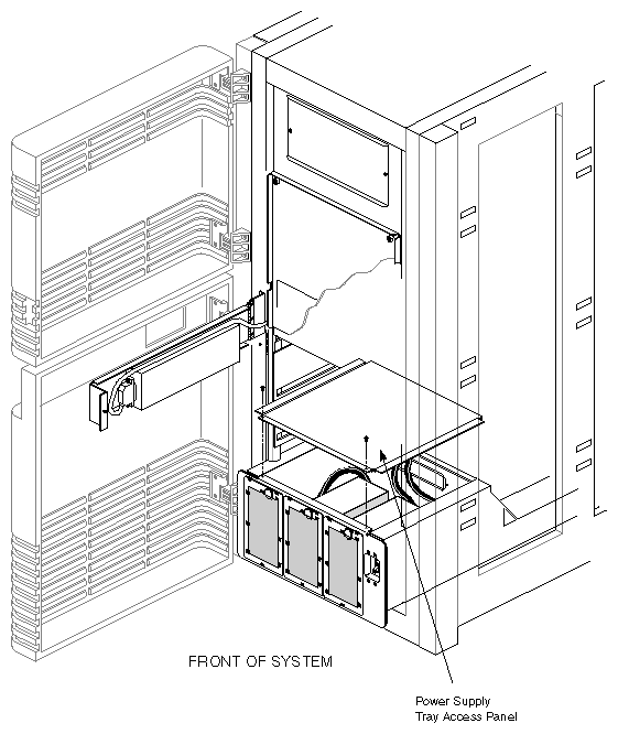
Remove the access panel from the top of the installed power supply tray by unfastening the two screws (see Figure 3-44).
Remove the access panel that isolates the SCSIBox enclosure from the midplane jumper board. The access panel is positioned by two alignment pins at its top edge and secured by four quarter-turn screws.
Note: The quarter-turn screws used with the access panel are not spring-loaded like the ones used with the I/O panels and do not release positively when turned. You must turn each one back and forth slightly while pulling gently on the corner it secures in order to release it. Loosen the ten screws securing the midplane/Cardcage 3 backplane access port cover to the right side of the cabinet. Lift the cover slightly and remove it from the cabinet.
Unfasten the nine connectors from the midplane jumper board (see Figure 3-45). The five connectors at the top of the jumper board come from the midplane. The four lower connectors come from the power supply tray.
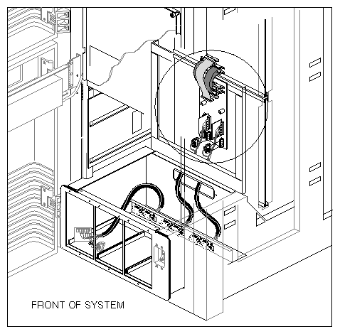
Remove the place that covers midplane connectors (see the circled area in Figure 3-45). Disconnect the cables and connectors from the midplane and pull the four power supply cables (two bundles), back through the cable port and into the power supply tray.
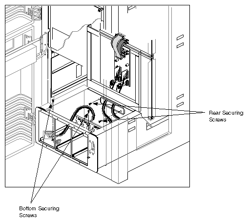
Remove all of the OLSs installed in the power supply tray (three screws per OLS). Locate the four screws securing the power supply tray to the system cabinet and remove them (see Figure 3-46).
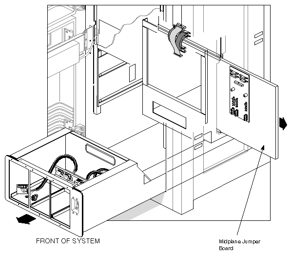
Withdraw the power supply tray from the front of the system cabinet (see Figure 3-47).
Withdraw the midplane jumper board through the access port on the right side of the cabinet (see Figure 3-47).
Note: The jumper board is held in position by friction. There is no mounting hardware.
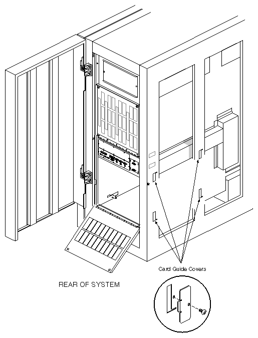
Remove the four card guide covers from the left side of the cabinet. Each cover is mounted with a single screw (see Figure 3-48).
Install the upper and lower Cardcage 3 card guides. Each card guide has four locating tabs (one in each corner). Make sure the tabs are perpendicular to the flange. The tabs fit into slots in the sides of the system chassis (see Figure 3-49).
Tip each guide so that the left-hand locating tabs (as seen from the rear of the system) engage the small slots in the left side of the chassis first. Insert the right-hand tabs into the larger openings on the right side of the chassis. Lower/raise the right side until the card guide is level. Then position each guide back as far as it will go in the locating slots.
Reinstall the four card guide covers on the left side of the cabinet.
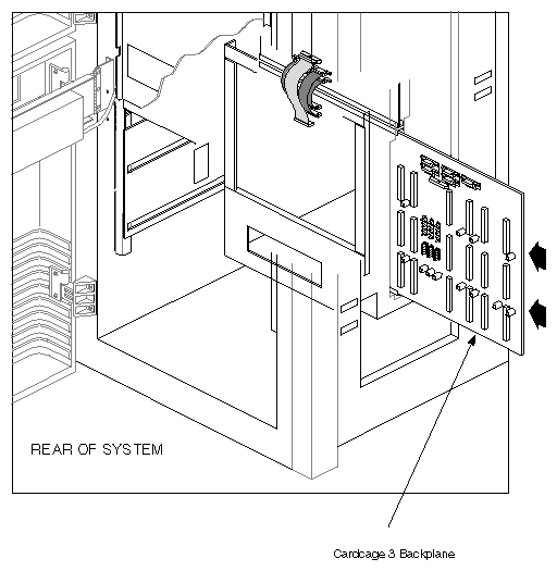
Slide the Cardcage 3 backplane into the system chassis (see Figure 3-50). Feed the top and bottom wedgelocks into the U-shaped mounting tracks a section at a time, until the two locating pins on the backplane's left side engage the corresponding holes in the side of the system cabinet. Verify that the two locating pins on the right side of the Cardcage 3 backplane align with and fit through the slots in the sheet metal access cover.
Note: If the locating pins on the Cardcage 3 backplane do not align with the slots in the sheet metal midplane/Cardcage 3 backplane access cover, refer to the procedure in the following step to work around the problem.
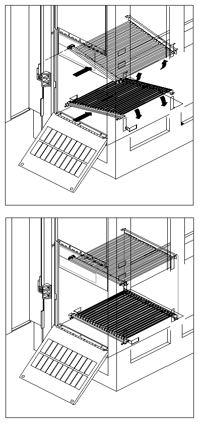
The video clip above illustrates the guide pins and shows how to install the Cardcage 3 backplane in the rackmount chassis. Notice how the backplane is jiggled slightly to align the wedgelocks in the U-shaped mounting tracks. The view in this video is from the rear of the system looking towards the front.
This step provides a solution for the misalignment of the right-side locating pins on the Cardcage 3 backplane and the slots in the sheet metal access cover. Go to the next step if this is not a problem. Remove the backplane and use a small Phillips-head screwdriver to remove the six screws (three on each side) that hold the lower backplane stiffener in place. Replace the backplane and proceed to the next step.
Slide the top and bottom card guides forward until the guide's locating pins have mated with the corresponding holes in the backplane. Tighten the screws that hold guides in place.
Use a 3/32-inch hex wrench to tighten the wedgelocks located at the top and bottom corners of the backplane.
Reinstall the midplane/Cardcage 3 backplane access port cover. Verify that the two pins on the right side of the backplane engage the two corresponding slots in the cover. Refer to steps 19 and 20 if they do not. Tighten the six screws that secure the cover.
Remove all OLSs and the access cover from the top of the new three-phase power supply tray that is part of the upgrade package.
Slide the power supply tray into the front of the cabinet. Ensure that the rear of the tray engages the rails mounted to the floor of the cabinet.
Secure the tray to the system cabinet using the four screws removed in Step 12.
Attach the five connectors from the midplane, and the six connectors from the new power supply tray, to the Cardcage 3 backplane as shown in Figure 3-51.
Reinstall the OLSs in the new power supply tray.
Reinstall the access cover.
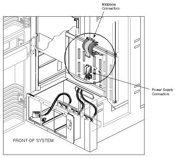
Continue to the next section and ensure that all system power and ground requirements are met. Then proceed to Section 3.11.5, "Configuring Cardcage 3," to install and cable the system boards.
The following sections define the power, ground, and electrical outlet connection requirements for both North American and international versions of the Challenge/Onyx rack products.
All 3-phase 4-wire versions of the Challenge/Onyx rack products (CMN A010D) must be connected to electrical outlets rated as follows:
Nema L15-30R
250V
30 amps
50/60 Hz
The socket outlet should be installed near the equipment and should be easily accessible.
All North American 3-phase, 4-wire versions of the Challenge/Onyx rack products (CMN A010D) must meet the following specifications:
An insulating grounding conductor must be installed that is identical in size, insulation material, and thickness to the grounded and ungrounded branch circuit supply conductors.
It must be green in color and may or may not have yellow stripes.
The conductor must be installed as part of the branch circuit that supplies the unit or system.
The grounding conductor must be connected to ground at the service equipment or, if supplied by a separately derived system, at the supply transformer or motor-generator set.
The attachment-plug receptacles in the vicinity of the system must all be the grounding type and the grounding conductors serving the receptacles must be connected to the ground at the service equipment.
All 3-phase, 5-wire European type "WYE" versions of the Challenge/Onyx rack products (CMN A010Y) must be connected to electrical outlets rated as follows:
3/N/PE
AC 360-480V
30 amps minimum
50/60 Hz
All 3-phase, 5-wire European type "WYE" versions of the Challenge/Onyx rack products (CMN A010Y) must meet the following specifications:
The electrical outlet to which the system is connected must be a 3-phase, 5-wire "WYE" connection with both neutral and earth ground terminals as well as terminals for each of the three-phase conductors.
The integrity of the neutral connection must be verified in order to avoid damage to the off-line switchers (OLSs).
For connection to "IT" power systems, a 4-pole breaker must be available at the building site.
Included in the Cardcage 3 upgrade kit is a label that must be applied over the "MODEL NO:" section of the original system serial number label. This label was applied to the unit at the factory and is similar to: P/N 024-0603-001.
The label is located on the sheet metal base of the chassis, and is directly above the front right caster. It is visible when standing in front of the rack with the door open. Follow these steps to properly apply the regulatory labels:
Apply the new model number label so that it completely covers the original model number.
Apply the system rating label. It must be positioned on the lower right-hand corner of the system serial number label. This label should overlap the edges of the system label in order to avoid covering up any of the certification symbols.
Note: These labels must be applied to all systems that receive the Cardcage 3 upgrade in the field. They are required by regulatory and safety organizations for the installation of Cardcage 3.
Before the third cardcage (Cardcage 3) can be populated with either VMEbus or graphics boards, a combination of system boards must be installed. These boards include:
a second IO4 board
Short and/or Long F Mezz boards
Remote VCAMs
505 and 512 power boards
VMEbus interrupt boards
VMEbus backplane terminators
VMEbus backplane jumpers
Also, in order to use some of the additional I/O capabilities (such as additional Ethernet ports, or serial ports), some system configuration is required. See the system(4) reference page and Section 3.12, "Software Configuration" for information about editing IRIX system configuration files.
This section covers the labelling, installation, and cabling of these boards in both server and graphics systems.
| Caution: Observe proper ESD procedures when handling the boards. Ensure that the boards are correctly seated in the backplane connectors and that the ejector tabs have engaged the top and bottom card guides. |
This section provides the cardcage slot assignments for multiple-IO4 configurations, as well as the labelling conventions for the IO4 boards and their I/O adapters. The I/O adapters involved in the configuration of Cardcage 3 are the two Flat Cable Interfaces (FCIs) mounted on each IO4 board and the FCIs on any installed F Mezz boards. The physical locations and specific configurations of the IO4 board(s) and F Mezz board(s) have a direct relationship on the labelling of each of the I/O adapters. The adapter labelling is, in turn, crucial in the software configuration phase of this upgrade.
See Table 3-18 for the slot assignments for multiple-IO4 boards.
Table 3-18. Server and Graphics System IO4 Board Slot Assignments
IO4 Board Number | CC2 Server slot | CC2 Graphics slot |
|---|---|---|
1st | 15 | 11 |
2nd | 13 | 9 |
3rd | 11 | 7 |
4th | 9 | 5 |
| Note: Use of all physically available serial, parallel, and Ethernet connectors may be restricted by the IRIX software release the system is running. Be sure to check all system release notes pertaining to the hardware and software before configuring a Challenge/Onyx rack with multiple IO4s. |
Figure 3-52 identifies the position of the IO4 boards on the server's Cardcage 2 I/O panel and the cabling from the I/O panel to the Cardcage 2 slots. As shown in Figure 3-52, IO4 boards are installed in a counterclockwise order, starting with the lower horizontal I/O panel cutout.
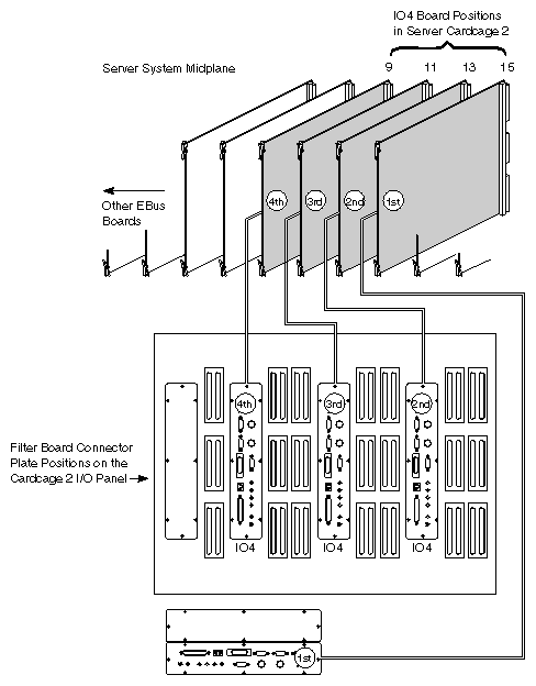
Figure 3-53 identifies the position of the IO4 boards in the Onyx graphics system Cardcage 2. The I/O panel and the cabling from the I/O panel to the Cardcage 2 slots are also shown.
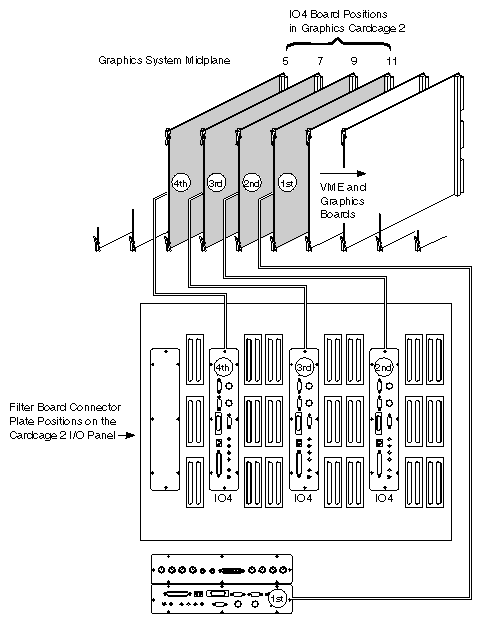
Labelling IO4 Board Connector Plates
The IO4 board labels match the board's bus and slot number. For example, since the first IO4 board in a server system resides in slot 15, the IO4 board number is EBus 15. Since IO4 boards are only installed on one side of the midplane, all slot numbers are odd.
In the Onyx graphics rack system, the first IO4 must go in slot 11, so the slot numbers will differ from those shown for the server system in Figure 3-54. The rules for placement remain the same as in the server system.
| Note: The second (top) horizontal I/O panel cutout in Cardcage 2 is only used for graphics connectors. |
The labels are placed above the IO4 board's connector plate on the I/O panel. For the horizontal IO4 connector plate, the label is at the upper left corner of the plate. For vertical IO4 connector plates, the labels are placed between the parallel port and the AUI ethernet connector (see Figure 3-54).
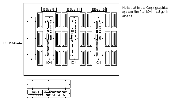
Labelling Connectors
Connectors are labelled sequentially, starting with the first IO4 board and proceeding through all installed IO4 boards. For example, the first serial connector on the first IO4 board is labelled tty_1. See Table 3-19 for information on labelling a server system and Table 3-20 for labelling a graphics system.
Table 3-19. Server System IO4 Filter Board Connector Labelling
IO4 Board Number | IO4 Filter Board Label (Server) | Serial Connectors | Server Parallel Connectors | Network Connectors |
|---|---|---|---|---|
1 | EBus 15 | RS-232: tty_1-3[a] RS-422: tty_4 | plp15 | et0 |
2 | EBus 13 | tty_45-47[b] | plp13 | et1 |
3 | EBus 11 | btty_49-51 | plp11 | et2 |
4 | EBus 9 | btty_53-55 | plp9 | et3 |
[a] Connectors are labelled sequentially from right to left. [b] Connectors are labelled sequentially from top to bottom. | ||||
Table 3-20. Graphics System IO4 Filter Board Connector Labelling
IO4 Board Number | IO4 Filter Board Label (Graphics System) | Serial Connectors | Graphics System Parallel Connectors | Network Connectors |
|---|---|---|---|---|
1 | EBus 11 | RS-232: tty_1-3[a] RS-422: tty_4 | plp11 | et0 |
2 | EBus 9 | tty_45-47[b] | plp9 | et1 |
3 | EBus 7 | btty_49-51 | plp7 | et2 |
4 | EBus 5 | btty_53-55 | plp5 | et3 |
[a] Connectors are labelled sequentially from right to left. [b] Connectors are labelled sequentially from bottom to top. | ||||
Serial Connectors
Serial connectors are labelled tty_#, where # is a one or two-digit integer. Numbering is sequential, from 1 through 4, 45 through 47, 49 through 51, and 53 through 55. Numbers 5 through 44, 48, and 52 are reserved or used for other optional serial devices.
To alert the system to the presence of a new IO4, you must edit the file /var/sysgen/system/irix.sm. When adding an IO4 to the Challenge/Onyx, you must edit the "EPC serial" information section to include new information about the placement of the IO4. See the system(4) reference page and Section 3.12, "Software Configuration."
Serial connector tty_4 is an RS-422 receptacle located on the first IO4 board (EBus 15 on a server, EBus 11 on a graphics system). All other serial connectors are RS-232 receptacles.
Parallel Connectors
Parallel connectors are labelled plp#, where # is a one- or two-digit integer. Numbering relates to the IO4 board's slot number. For example, on the IO4 board, EBus 11, the parallel connector is labelled plp11.
Ethernet Network Connectors
Ethernet connectors are labelled et#, where # is a single-digit integer. Numbering is sequential from 0 to 3, starting at the first IO4 board, (EBus 15 or EBus 11).
Each IO4 board provides a 15-pin AUI Ethernet connector. Only one connector may be used at a time for each IO4 board, for a total of four IO4-based Ethernet connections on a system with the maximum number of IO4 boards.
To enable the use of an additional Ethernet connector on a new IO4 board, you must edit the file /var/sysgen/system/irix.sm. When adding an IO4 to the Challenge/Onyx you must edit the "EPC Ethernet" information section to include new information about the additional IO4. See the system(4) reference page and Section 3.12, "Software Configuration," for additional information about editing this file.
I/O Adapter Labelling
Each IO4 board supports six I/O devices. Each of the six devices is assigned a unique I/O Adapter number, as shown in Table 3-21.
Table 3-21. I/O Adapter Labelling
I/O Adapter Number | Device Description |
|---|---|
1 | Everest Peripheral Controller (EPC ASIC) |
2 | Flat Cable Interface to lower F ASIC |
3 | Flat Cable Interface to VMEbus (upper F ASIC) |
4 | SCSI Controller (S1 ASIC) |
5 | ASIC in Lower Mezz Card Location |
6 | ASIC in Upper Mezz Card Location |
The I/O Adapters used with Cardcage 3 are the two F ASICs mounted on each IO4 board (I/O Adapters 2 and 3) and the F ASICs on any installed F Mezz cards (I/O Adapters 5 and 6). The relationship of these adapters to the physical board connectors is illustrated in Figure 3-55. The labelling convention for each connector is F-XX-N, where "F" specifies an F ASIC, "XX" represents the Cardcage 2 slot number, and "N" is the I/O Adapter number.
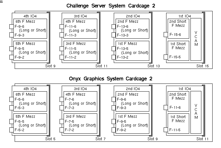
| Note: Figure 3-55 shows every possible position of an F Mezz board filled. It is highly unlikely that any rack system would be configured in this manner. It is likely that the system would have SCSI expansion Mezz boards or other Mezz board options installed on some of the IO4 mezzanine locations. |
Install, cable, and configure the system boards as follows:
| Note: Graphics machines with a Cardcage 3 upgrade require an additional, dedicated IO4 board with either one or two long F Mezz boards mounted on it. |
Mount the F Mezz cards to the IO4 board that came as part of the Cardcage 3 upgrade. Use the standoffs and mounting hardware provided.
If the IO4 board that came as part of the Cardcage 3 upgrade will be the second IO4 in the system, install it in Slot 9. If it will be the third IO4, install it in Slot 7. And if it will be the fourth IO4 board, install it in Slot 5.
In configurations where a single graphics pipe (board set) will occupy Cardcage 3, install the Remote VCAM board in Slot 1. If the configuration calls for a second graphics pipe in Cardcage 3, install the second Remote VCAM in Slot 12.
Systems with a single graphics pipe in Cardcage 3 are cabled as shown in Figure 3-56. Systems with two graphics pipes are cabled as shown in Figure 3-57.
Attach the ribbon cables to the IO4 board connectors as shown. Route each cable from CC2 down through the cable ports immediately behind the main I/O panel. Attach the remaining end of each cable to the corresponding connector on the Remote VCAM.
Note: All cables are the 60-pin micro-strip cable (P/N 9290049). These cables are silver mylar and are split into separate ribbons at the connectors.
The I/O adapter labeling for each FCI connector changes with the location of the F Mezz cards. Ensure that F Mezz cards installed in the locations shown in the following figures are cabled exactly as illustrated.
Note: No jumper or terminator boards are installed on a Cardcage 3 graphics backplane. There are no optional configurations other than using either or both of the pipes provided Install one 512 power board and five 505 Power boards as shown in Figure 3-58.
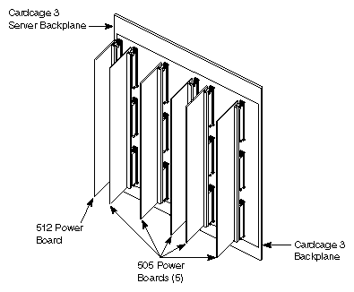
The video clip above illustrates how to install power boards on the Cardcage 3 backplane.
Reinstall the access panel isolating the Cardcage 3 backplane from the SCSIBox(es).
Reinstall and cable the SCSIBox(es).
Install the SCSI cable access port cover and inside blanking cover (if present).
Reinstall the side panels.
Attach the hinge of the new I/O option door to the system chassis.
Install the graphics board set(s) as indicated by the labels on the card guide.
Close the Cardcage 3 I/O option door, then close the chassis rear door.
Connect the AC power cord to the supply voltage and power up the system as described in Section 3.8, "Bringing the System Up and Down." Then, continue with Section 3.12, "Software Configuration."
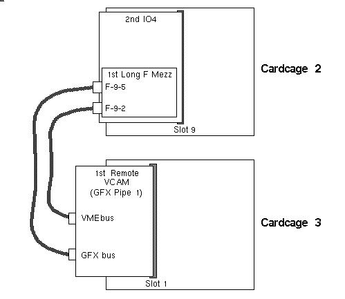
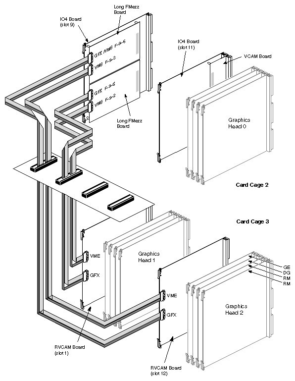
The Cardcage 3 upgrade for servers provides up to four additional VMEbuses. This upgrade can require an additional IO4 board, and Short and/or Long F Mezz cards, depending on the number of VMEbuses desired.
| Note: The Cardcage 3 upgrade in Challenge XL systems requires a PROM upgrade to the System Controller board. See Section 3.13, "Upgrading the PROM on the System Controller Board,". |
The placement of the F Mezz cards in Cardcage 2, and whether additional IO4 boards are required, is determined in part by the configuration of the installed IO4 board and by the type of F Mezz card shipped with the upgrade. The cardcage configuration is then determined by the installation of jumper and/or terminator boards on the rear of the backplane.
| Note: Each remote VCAM is only capable of supplying a maximum of 1 amp in the –12V and –5V range. This may limit or restrict the number and/or type of VME boards installed in each Cardcage 3 VMEbus bank. The installer should pay special attention to this fact when installing a single remote VCAM supporting multiple banks of VME boards. |
The following subsections provide examples of some of the many possible configurations.
One Cardcage 3 VMEbus
Open the rear chassis access door and the Cardcage 2 I/O panel. Check the configuration of the IO4/VCAM board assembly in Slot 15 of Cardcage 2. If an open Mezz card slot is available, withdraw the IO4/VCAM from the cardcage and mount the Short F Mezz card using the standoffs and mounting hardware provided.
Note: If the installed IO4 board's Mezz card slots are occupied, or if you are installing a Long F Mezz card, mount the card on a second IO4 board. Install the second IO4/F Mezz assembly in Slot 13. Install the Remote VCAM board in Slot 1 of Cardcage 3.
Attach the silver mylar ribbon cable to the IO4 board connector as shown in Figure 3-59 or Figure 3-60 (depending on the type of F Mezz card installed). Route the cable from CC2 down through the cable port immediately behind the main I/O panel. Attach the remaining end of the cable to the upper connector on the Remote VCAM board.
Note: The bottom connector on the Remote VCAM board is dedicated to the graphics bus and must never be used in a Cardcage 3 configured for one or more VMEbuses. Note: All cables are the 60-pin micro-strip cable (P/N 9290049). These cables are silver mylar and are split into separate ribbons at the connectors.
The I/O adapter labelling for each FCI connector changes with the location of the F Mezz cards. Ensure that F Mezz cards installed in the locations shown in the following figures are cabled exactly as illustrated.
.
Working from the front of the chassis, connect the four separate VMEbuses by installing jumper boards in the locations called out in Figure 3-61. Install a single terminator board as shown.
Note: There are three separate types of jumper board: J1, J2, and J3. Each jumper board must be inserted into its corresponding connector on the backplane.
Install one 512 Power board and three 505 Power boards in the locations shown in Figure 3-62.
The video clip above illustrates how to install power boards on the Cardcage 3 backplane.
Reinstall the access panel isolating the Cardcage 3 backplane from the SCSIBox(es).
Reinstall and cable the SCSIBox(es).
Install the SCSI cable access port cover and inside blanking cover (if present).
Reinstall the side panels.
Attach the hinge of the new I/O option door to the system chassis.
Install the VMEbus boards as indicated by the labels on the card guide.
Note: The cardcage slots labeled "Remote VCAM VME" can be used for standard VMEbus boards.
If there are any empty card slots between boards, an interrupt board (P/N 030-0516-00x) must be installed in connector P1 (top) of that board slot.Close the Cardcage 3 I/O option door, then close the chassis rear door.
Connect the AC power cord to the supply voltage and power up the system as described in Section 3.8, "Bringing the System Up and Down." Then, continue with Section 3.12, "Software Configuration."
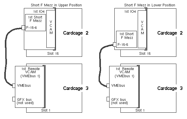
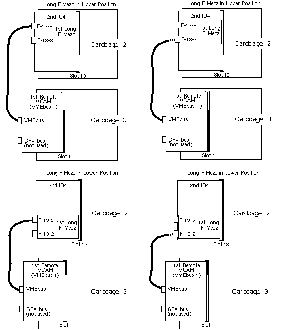
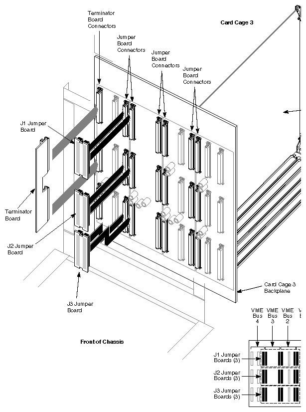
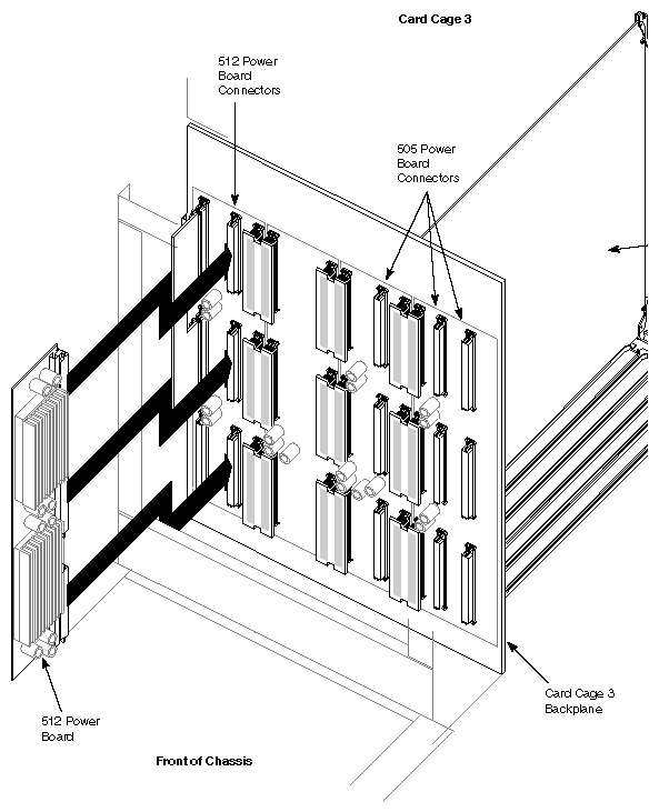
Two Cardcage 3 VMEbuses
Open the rear chassis access door and the Cardcage 2 I/O panel. Check the configuration of the IO4/VCAM board assembly in Slot 15 of Cardcage 2. If one or two open Mezz card slots are available, withdraw the IO4/VCAM from the cardcage and mount one or both of the Short F Mezz cards using the standoffs and mounting hardware provided.
Note: If the installed IO4 board's Mezz card slots are occupied, or if the upgrade was shipped with Long F Mezz cards, the cards must be mounted on a second IO4 board. Install the second IO4/F Mezz assembly in Slot 13. Install the first Remote VCAM board in Slot 1 of Cardcage 3.
Install the second Remote VCAM board in Slot 12 of Cardcage 3.
Attach a silver mylar ribbon cable to each of the two IO4 board connectors as shown in Figure 3-63 or Figure 3-64. Route the cables from CC2 down through the cable ports immediately behind the main I/O panel. Attach the remaining end of the cables to the upper connector on each of the Remote VCAM boards.
Note: The bottom connector on the Remote VCAM board is dedicated to the graphics bus and must never be used in a Cardcage 3 configured for one or more VMEbuses.
Working from the front of the chassis, connect each pair of VMEbuses by installing jumper boards in the locations designated in Figure 3-65. Install the two terminator boards as shown.
Note: There are three separate types of jumper board: J1, J2, and J3. Each jumper board must be inserted into its corresponding connector on the backplane.
Install one 512 power board and three 505 power boards (refer to Figure 3-58).
Reinstall the access panel isolating the Cardcage 3 backplane from the SCSIBox(es).
Reinstall and cable the SCSIBox(es).
Install the SCSI access port cover and inside blanking cover (if present).
Reinstall the side panels.
Attach the hinge of the new I/O option door to the system chassis.
Install the VMEbus boards as indicated by the labels on the card guide.
Note: The cardcage slots labeled "Remote VCAM VME" can be used for standard VMEbus boards.
If there are any empty card slots between boards, an interrupt board (P/N 030-0516-00x) must be installed in connector P1 (top) of that board slot.Close the Cardcage 3 I/O option door, followed by the chassis rear door.
Connect the AC power cord to the supply voltage and power up the system as described in Section 3.8, "Bringing the System Up and Down." Then, continue with Section 3.12, "Software Configuration."
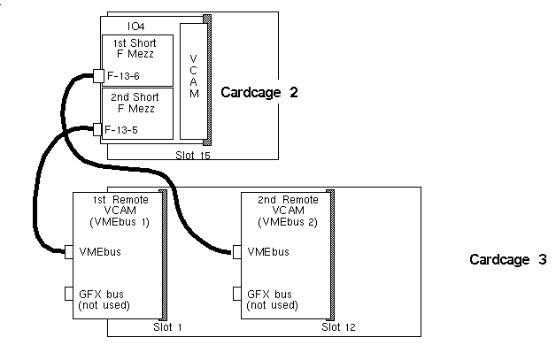
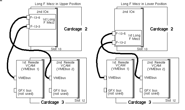
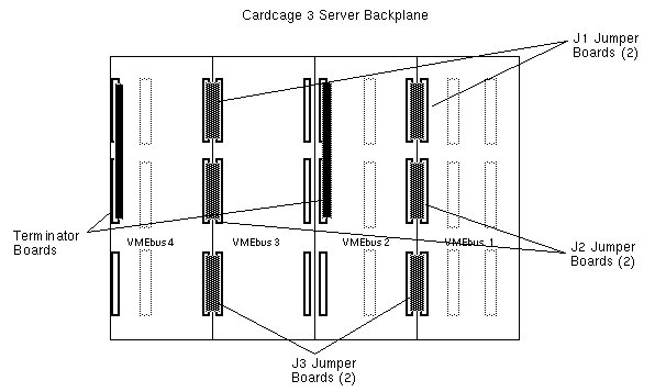
Three Cardcage 3 VMEbuses
Open the rear chassis access door and the Cardcage 2 I/O panel. Check the configuration of the IO4/VCAM board assembly in Slot 15 of Cardcage 2. If one or two open Mezz card slots are available, withdraw the IO4/VCAM from the cardcage and mount one or two Short F Mezz cards using the standoffs and mounting hardware provided.
If the installed IO4 board's Mezz card slots are occupied, or if the upgrade was shipped with Long F Mezz cards, the F Mezz cards must be mounted on a second IO4 board. Install the second IO4/F Mezz assembly in Slot 13.
Install the first Remote VCAM board in Slot 1 of Cardcage 3.
Install the second Remote VCAM board in Slot 7 of Cardcage 3.
Install the third Remote VCAM board in Slot 12 of Cardcage 3.
Attach a silver mylar ribbon cable to each of the IO4 board connectors as shown in Figure 3-66 and Figure 3-67. Route the cables from CC2 down through the cable ports immediately behind the main I/O panel. Attach the remaining end of the cables to the upper connector on each of the Remote VCAM boards.
Note: The bottom connector on the Remote VCAM board is dedicated to the graphics bus and must never be used in a Cardcage 3 configured for one or more VMEbuses.
Working from the front of the chassis, configure the Cardcage 3 backplane for three VMEbuses by installing the jumper and terminator boards in the locations called out in Figure 3-68.
Note: There are three separate types of jumper board: J1, J2, and J3. Each jumper board must be inserted into its corresponding connector on the backplane.
Install one 512 power board and three 505 power boards (refer to Figure 3-58).
Reinstall the access panel isolating the Cardcage 3 backplane from the SCSIBox(es).
Reinstall and cable the SCSIBox(es).
Install the SCSI access port cover and inside blanking cover (if present).
Reinstall the side panels.
Attach the hinge of the new I/O option door to the system chassis.
Install the VMEbus boards as indicated by the labels on the card guide.
Note: The cardcage slots labeled "Remote VCAM VME" can be used for standard VMEbus boards.
If there are any empty card slots between boards, an interrupt board (P/N 030-0516-00x) must be installed in connector P1 (top) of that board slot.Close the Cardcage 3 I/O option door, then close the chassis rear door.
Connect the AC power cord to the supply voltage and power up the system as described in Section 3.8, "Bringing the System Up and Down." Then, continue with Section 3.12, "Software Configuration."
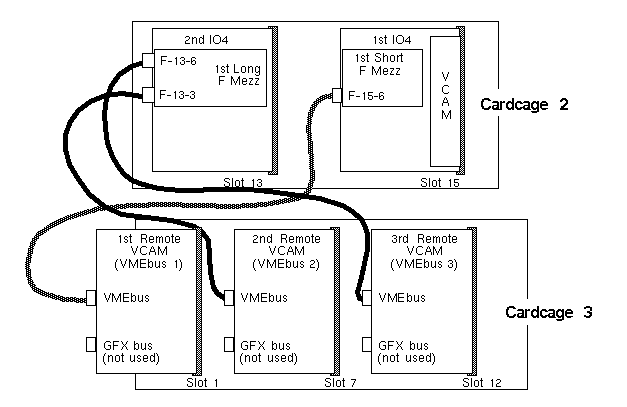
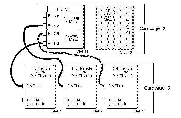
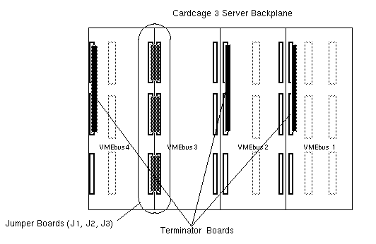
Four Cardcage 3 VMEbuses
Open the rear chassis access door and the Cardcage 2 I/O panel. Check the configuration of the IO4/VCAM board assembly in Slot 15 of Cardcage 2. If one or two open Mezz card slots are available, withdraw the IO4/VCAM from the cardcage and mount one or two Short F Mezz cards using the standoffs and mounting hardware provided.
If the installed IO4 board's Mezz card slots are occupied, or if the upgrade was shipped with Long F Mezz cards, the F Mezz cards must be mounted on a second IO4 board. Install the second IO4/F Mezz assembly in Slot 13.
Install the first Remote VCAM board in Slot 1 of Cardcage 3.
Install the second Remote VCAM board in Slot 7 of Cardcage 3.
Install the third Remote VCAM board in Slot 12 of Cardcage 3.
Install the fourth Remote VCAM board in Slot 17 of Cardcage 3.
Attach a silver mylar ribbon cable to each of the IO4 board connectors as shown in Figure 3-69 and Figure 3-70. Route the cables from CC2 down through the cable ports immediately behind the main I/O panel. Attach the remaining end of the cables to the upper connector on each of the Remote VCAM boards.
Note: The bottom connector on the Remote VCAM board is dedicated to the graphics bus and must never be used in a Cardcage 3 configured for one or more VMEbuses.
Working from the front of the chassis, configure the Cardcage 3 backplane for four VMEbuses by installing the terminator boards in the locations called out in Figure 3-71.
Install one 512 power board and three 505 power boards (refer to Figure 3-58).
Reinstall the access panel isolating the Cardcage 3 backplane from the SCSIBox(es).
Reinstall and cable the SCSIBox(es).
Install the SCSI access port cover and inside blanking cover (if present).
Reinstall the side panels.
Attach the hinge of the new I/O option door to the system chassis.
Install the VMEbus boards as indicated by the labels on the card guide.
Note: The cardcage slots labeled "Remote VCAM VME" can be used for standard VMEbus boards.
If there are any empty card slots between boards, an interrupt board (P/N 030-0516-00x) must be installed in connector P1 (top) of that board slot.Close the Cardcage 3 I/O option door, followed by the chassis rear door.
Connect the AC power cord to the supply voltage and power up the system as described in Section 3.8, "Bringing the System Up and Down." Then, continue with Section 3.12, "Software Configuration."
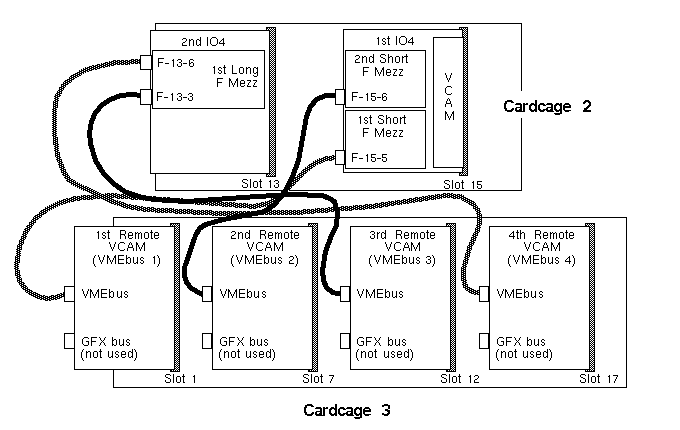
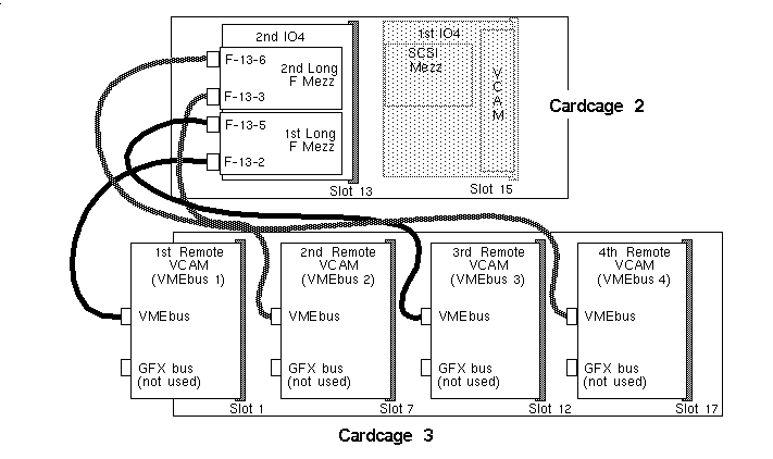
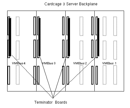
After installing the Cardcage 3 and other related hardware upgrades, you may need to use some or all of the information in the following three subsections to properly configure the system.
After setting up the hardware as previously described, modify the /var/sysgen/system/irix.sm file as follows:
Power up the system and then open up a shell.
Become superuser and use an editor (such as vi) to open the /var/sysgen/system/irix.sm file.
Locate the appropriate vector statement in the file. Be sure the board controller number matches the vector line you modify. See the following example:
VECTOR: bustype=VME module=jag ipl=1 ctlr=0 adapter=0 iospace=(A16S, 0, 0x800)
probe_space=(A16S, 0, 1)
Note: Later in this procedure, you will change the adapter number (i.e., adapter=0) to reflect the position of the F Mezz board on the IO4 board. The adapter number, 0, designates the primary bus in the midplane. Changing the adapter number through the following software procedure will enable the configuration that you have just set up through hardware installation. Determine the slot position of the IO4 board that has the targeted F Mezz board mounted on it (see the "IO4 Board Locations and Labelling" section).
Determine the adapter position(s) of the F Mezz board that you are using (see the "I/O Adapter Labelling" section).
You can also use the hinv -v -b command to determine both the IO4 slot number and the IO4 adapter position of the F Mezz board connector.
Translate the adapter position number into its corresponding virtual adapter number using Table 3-22. For example, physical adapter 5 translates to position 2 and adapter 6 translates to position 3.
Table 3-22. Translating I/O Adapter Numbers
I/O Adapter Number
Translated Adapter Number
2
0
3
1
5
2
6
3
Note: The software requires this virtual translation to help determine the corresponding VMEbus bank. You can now determine and change the adapter number (i.e., adapter=0) in the vector statement by using the following formula and entering the values just derived:
adapter number = [IO4 slot# x (multiplied by) 4] + translated adapter_position
As an example, say you to wish to enable a separate VMEbus for VME boards attached through Short F Mezz board connector 6 on an IO4 board in slot 15. According to the formula, you would take the IO4 slot number 15, multiply it by 4, and then add the translated adapter position number 3 to obtain a value of 63.
Afterwards, you must then change the default adapter number, 0 (i.e., adapter=0), to a value of 63. This tells the driver where its controller can be found.
If applicable, remove the * (asterisk) from the desired vector line and edit the statement with the new adapter number value.
If you wish to add another VME device or enable another VMEbus, edit the next vector line with the desired adapter number.
Note: If you are adding a third-party board that has not been acquired through Silicon Graphics, you may have to select a different IO space address range value in the vector statement. Check the third-party board documentation and compare the range against the preset ranges. Halt the system and then reboot. During boot-up, you should see a message similar to the following:
... automatically reconfiguring the system...
Note: If you do not see this message, this indicates that either the hardware was not properly configured or that the software file was not properly modified. Recheck the hardware and software configuration. Halt and reboot the system again to fully enable all drivers and the system kernel.
Run the hinv command to verify that the additional boards are recognized by the operating system.
SCSI buses are added to the Challenge/Onyx system by adding additional IO4 boards or adding SCSI mezzanine boards to existing IO4s.
SCSI bus connector and cable labeling is done to provide physical identification of the buses. Label syntax is:
DF SCSI SSn (for differential buses)
SE SCSI SSn (for single-ended buses)
SS is the EBus slot number of the IO4 where the cable originates and n is the relative bus number on the IO4. In the directory /dev are the names for each SCSI bus that are derived from the SSn label using the syntax:
/dev/{r}dsk/dksSSndDsP |
SSn is the same as the cable/connector label. dDsP reports the drive D and slice/partition P.
| Note: The first IO4 in a system has a simplified /dev identifier and the SS slot designator is not required. SCSI buses on additional IO4s in the system must use the SS slot designator. |
Reconfiguration of the kernel is not required for SCSI expansion. Challenge/Onyx SCSI devices always use the naming scheme where the device name requires specifying the originating IO4 board's slot number.
After the new configuration information has been input, type the following commands to the shell:
% su # cd /dev # ./MAKEDEV dks |
Each IO4 has built-in Ethernet, serial, and parallel ports. These devices are configured in IRIX by modifying vector statements in /var/sysgen/system/irix.sm. The vector statements are located in the file under the subheading of "bustype=EPC".
Note that the parallel port does not require the same configuration as serial and Ethernet ports. It uses a physical naming scheme where the name of the device requires specifying the slot number in which the IO4 resides.
The serial and Ethernet ports on IO4s require specifying the EBus slot number of the particular IO4 where they originate. For serial ports, there is one vector line per IO4 board with the "unit" field values as shown in Table 3-23
Table 3-23. Serial Port Vector Field Values
Location | /dev/ttyXX | Unit= |
|---|---|---|
First IO4 | tty?1, tty?2, tty?3, tty?4 | 0 |
Second IO4 | tty?45, tty?46, tty?47 | 1 |
Third IO4 | tty?49, tty?50, tty?51 | 2 |
Fourth IO4 | tty?53, tty?54, tty?55 | 3 |
The vector line field "slot=" value must be set to the decimal number of the EBus slot in which the IO4 is installed.
| Note: The first IO4 board in the system always uses a special "slot" value of 0. |
After the new configuration information has been input, you must run /dev/MAKDEV to create the /dev/tty* entries. Execute this by typing the following commands to the shell:
% su # cd /dev # ./MAKEDEV ttys |
For the Ethernet interfaces, there is one vector line per board. Each "unit" field number corresponds to the device name numeric suffix: et0, et1, et2, and et3. As with the serial ports, the vector line field value for "slot=" must be set to the decimal number of the EBus slot the IO4 occupies. As noted previously, the first IO4 board always uses the "slot" value 0.
To create /dev entries for added parallel ports, run the /dev/MAKDEV file as follows:
% su # cd /dev # ./MAKEDEV plp |
This process will make entries for all the parallel devices seen by the hinv command.
This section describes how to upgrade the PROM on the System Controller board in the Challenge rackmount system. The System Controller board is one of the power boards that plug into the midplane in the rackmount system. This board contains the control logic for the system Status Panel display and also supplies power for the Ebus.
This firmware upgrade corrects the POKA failure that resulted when the Cardcage 3 was added to the Challenge rackmount system. Without a PROM upgrade, the POKA_FAIL condition may lead to system shutdown by the System Controller.
(The PROM upgrade causes the System Controller to wait slightly longer for backplane voltage to rise. With the additional capacitance of the power boards in Cardcage 3, system backplane voltage takes longer to rise to its operating value. Without the PROM upgrade, the System Controller does not wait long enough for the voltage to rise and shuts the system down prematurely with a POKA failure. The difference in time is approximately 100 ms.)
| Note: For a complete list of reporting error problems, see the associated software release notes. |
This upgrade applies to the following versions of the System Controller board:
030-0265-005 and below
030-0380-002 and below
| Note: Despite the two different part numbers, these boards are interchangeable in the field. The 030-0380-00x board is a slightly improved version of the 030-0265-xxx board. |
To remove the System Controller board, follow these instructions:
| Caution: Use proper electrostatic discharge (ESD) precautions when handling components by using an antistatic surface and wearing a grounding strap. |
Ensure that the system is backed up; then power down the system.
Open the front of the rackmount (XL chassis) system to access the System Controller board.
Remove the System Controller board from its slot on the front of the midplane.
Place the board on a soft, antistatic surface (such as an antistatic mat or foam padding).
| Note: The soft, compliant surface helps absorb the shock to prevent possible IC pin breakage when you install the PROM. |
See Figure 3-72 for the location of the PROM on the System Controller board.
Follow these instructions to install the new firmware:
| Caution: Use proper electrostatic discharge (ESD) precautions when handling components by using an antistatic surface and wearing a ground strap. |
Locate the old PROM (see Figure 3-72), then use an IC puller to remove this PROM from its location.
Note the orientation of the notch in Figure 3-72, then install the new PROM (P/N 070-1117-005). Be very careful not to bend or break any pins.
Attach the deviation authorization label to the System Controller PCB(DA# 799).
Install the updated System Controller board into its power board location.