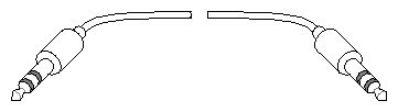
This appendix describes each of the system connectors and shows some of the monitor and keyboard cables that are available. It also describes the system interrupt cable.
Table C-1 through Table C-19 and Figure C-18 show the system connectors and their pin assignments.
Table C-1. I/O Panel Connectors - Parallel port 25-pin D-sub receptacle
Description | Pins | Signals | Flow (from chassis) |
|---|---|---|---|
Parallel port 25-pin D-sub receptacle | 1 2 3 4 5 6 7 8 9 10 11 12 13 14 15 16 17 18 19-25 | STB (Data strobe) Data 0 Data 1 Data 2 Data 3 Data 4 Data 5 Data 6 Data 7 Data ACK Busy PE: paper empty SLCT: select/online AUTOFD ERROR INIT (reset) NO INK not connected GND |
|
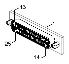
Table C-2. I/O Panel Connectors - Ethernet Port 15-pin AUI
Description | Pins | Signals | Flow (from chassis) |
|---|---|---|---|
Ethernet port 15-pin AUI (Attachment Unit Interface) according to IEEE 802.3 specification. Pin pairs 2:9, 3:10, and 5:12 are twisted pairs. Cabling is 9-conductor. | 1 2 3 4 5 6 7 8 9 10 11 12 13 14 15 | Logic Ground Collision + TXD + Logic Ground RXD + Power Return not used Logic Ground Collision – TXD – Logic Ground RXD – Power (+12V) Logic Ground not used |
two-way two-way
two-way input
two-way two-way
two-way output
|
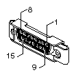
Table C-3. I/O Panel Connectors - Serial Port tty1 9-pin D-sub Receptacle
Description | Pins | Signals | Flow (from chassis) |
|---|---|---|---|
Serial port tty1 9-pin D-sub receptacle. RS-232 protocol. Serial ports 0 and 1 provide a choice of this or an 8-pin DIN receptacle. Only one receptacle from each port can be used at a given time. | 1 2 3 4 5 6 7 8 9 | not used TXD RXD RTS CTS GND GND DCD DTR |
output input output input
input output |

Table C-4. I/O Panel Connectors - Serial Ports tty2, tty3 for Unpowered Peripherals
Description | Pins | Signals | Flow (from chassis) |
|---|---|---|---|
Serial ports tty2, tty3 for unpowered peripherals. 9-pin D-sub receptacle. RS-232 protocol. Serial ports 0 and 1 provide a choice of this or an 8-pin DIN receptacle. Only one receptacle from each port may be used at a given time. | 1 2 3 4 5 6 7 8 9 | not used TXD RXD RTS CTS GND GND DCD DTR |
output input output input
input output |
Table C-5. I/O Panel Connectors - Serial Ports tty2, tty3 for Powered Peripherals
Description | Pins | Signals | Flow (from chassis) |
|---|---|---|---|
Serials ports tty2, tty3 for powered peripherals. 8-pin DIN receptacle. | 1 2 3 4 5 6 7 8 | DTR CTS Stereo Sync RXD TXD GND GND Power +10V | output input output input output
output |
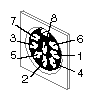
Table C-6. I/O Panel Connectors - Serial Port tty4 RS-422 Protocol
Description | Pins | Signals | Flow (from chassis) |
|---|---|---|---|
Serial port tty4 RS-422 protocol. 9-pin D-sub receptacle. | 1 2 3 4 5 6 7 8 9 | DTR TXD low –[a] RXD low –[b] DCD CTS GND aTXD high + bRXD high + RTS | output two-way two-way input input
two-way two-way output |
[a] Pins 2 and 7 must be twisted pair in cable. [b] Pins 3 and 8 must be twisted pair in cable. | |||
Table C-7. I/O Panel Connectors - System Interrupt IN Ports 0, 1
Description | Pins | Signals | Flow (from chassis) |
|---|---|---|---|
System Interrupt IN ports 0, 1 | tip ring sleeve | Interrupt Power +5V Shield | input |

Table C-8. I/O Panel Connectors - System Interrupt OUT Ports 0, 1, 2, 3
Description | Pins | Signals | Flow (from chassis) |
|---|---|---|---|
System Interrupt OUT ports 0, 1, 2, 3 | tip ring sleeve | Interrupt Power +5V Shield | output |
Table C-9. I/O Panel Connectors - Keyboard/Mouse Port 0
Description | Pins | Signals | Flow (from chassis) |
|---|---|---|---|
Keyboard/mouse port 0 6-pin receptacle | 1 2 3 4 5 6 | KBD_RXD MOUSE_RXD SIG GND Power +12V KBD_TXD not used | input input
output output |
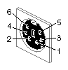
Table C-10. Video Panel Connectors - Swap Ready Port
Description | Pins | Signals | Flow (from chassis) |
|---|---|---|---|
Swap Ready port BNC receptacle Impedance 75 Ohm | center shield | SWAP_READY Chassis Ground | two-way |

Table C-11. Video Panel Connectors - Frame Grab Port
Description | Pins | Signals | Flow (from chassis) |
|---|---|---|---|
Frame Grab port BNC receptacle Impedance 75 Ohm | center shield | FRAME_GRAB Chassis Ground | input |
Table C-12. Video Panel Connectors - Composite Video Ports A, B
Description | Pins | Signals | Flow (from chassis) |
|---|---|---|---|
Composite video ports A, B BNC receptacle Impedance 75 Ohm | center
shield | CMPST_A or CMPST_B Chassis Ground | output |
Table C-13. Video Panel Connectors - S-VIDEO Ports A, B
Description | Pins | Signals | Flow (from chassis) |
|---|---|---|---|
S-VIDEO ports A, B 4-pin receptacle NTSC or PAL-compatible | 1 2 3 4 | LUMOND CHRMOND LUM CHRM | output output output output |
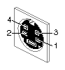
Table C-14. Video Panel Connectors - Monitor Port
Description | Pins | Signals | Flow (from chassis) |
|---|---|---|---|
Monitor port 13W3 receptacle | A1 A2 A3 1 2 3 4 5 6 7 8 9 10 | Red Green Blue not used Monitor type 0 not used Stereo Sync[a] aStereo Power +10V Monitor Type 1 Monitor Type 2 Ground aGround aGround | output output output
input
output output input input |
[a] On some cables these signals are not used. | |||
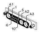
Table C-15. Video Panel Connectors - Alpha Port
Description | Pins | Signals | Flow (from chassis) |
|---|---|---|---|
Alpha port BNC receptacle Impedance 75 Ohm | center shield | Alpha Chassis Ground | output |
Table C-16. Video Panel Connectors - Sync Port
Description | Pins | Signals | Flow (from chassis) |
|---|---|---|---|
Sync port BNC receptacle Impedance 75 Ohm | center shield | Sync Chassis Ground | output |
Table C-17. Video Panel Connectors - Genlock IN, Genlock OUT
Description | Pins | Signals | Flow (from chassis) |
|---|---|---|---|
Genlock IN, Genlock OUT BNC receptacle Impedance 75 Ohm | center shield | Genlock loop-through Chassis Ground | two-way |
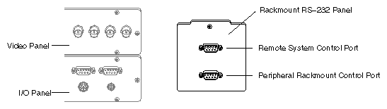
Table C-18. Rackmount Remote System Control Port
Description | Pins | Signals | Flow (from chassis) |
|---|---|---|---|
Rackmount remote system control port 9-pin D-sub receptacle | 1 2 3 4 5 6 7 8 9 | not used TXD RXD RTS CTS not used Ground DCD DTR |
output input output input
input output |
Table C-19. Peripheral Rackmount Power Control Port
Description | Pins | Signals | Flow (from chassis) |
|---|---|---|---|
Peripheral rackmount power control port 9-pin D-sub receptacle | 1 2 3 4 5 6 7 8 9 | PENE + PENE – not used POKE + POKE – not used not used not used not used | two-way two-way
two-way two-way |
This section identifies the monitor cables provided by Silicon Graphics. See Table C-20 for a summary of monitor cables and Table C-21 through Table C-26 for specific details of each cable.
Table C-20. Monitor Cable Summary
Description | Length | Connectors | Part Number |
|---|---|---|---|
Extension cable | 15' | 13W3 receptacle, both ends | 018-0285-001 |
Extension cable | 15' | 13W3 receptacle to 3 BNC plugs | 018-0286-001 |
Extension cable | 75' | 13W3 plug, both ends | 018-8094-002 |
Adapter cable | 1' | 13W3 receptacle to 3 BNC plugs | 018-0343-001 |
Adapter cable | 1' | 13W3 plug to 3 BNC receptacles | 018-0344-001 |
Extension cable | 75' | 3 BNC receptacles, both ends | 018-0275-003 |
 | Note: To attach a second graphics monitor to a Challenge/Onyx chassis, additional hardware is required to provide a second set of signals. |
Table C-21. Monitor Extension Cable, Round, 15' Length, Shielded, 13W3 Hybrid Plugs at Each End of Cable
Part Number | Description |
|---|---|
018-0285-001 | Monitor extension cable, round, 15' length, shielded, 13W3 hybrid plugs at each end of cable. |
Figure C-21. Monitor Extension Cable, Round, 15' Length, Shielded, 13W3 Hybrid Plugs at Each End of Cable
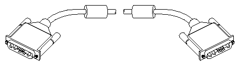 |
Table C-22. Monitor Extension Cable, Round, 15' Length, Shielded, 13W3 Hybrid Plug at Chassis End, 3 BNC Plugs (RGB) at Monitor End
Part Number | Description |
|---|---|
018-0286-001 | Monitor extension cable, round, 15' length, shielded, 13W3 hybrid plug at chassis end, 3 BNC plugs (RGB) at monitor end. |
Figure C-22. Monitor Extension Cable, Round, 15' Length, Shielded, 13W3 Hybrid Plug at Chassis End, 3 BNC Plugs (RGB) at Monitor End
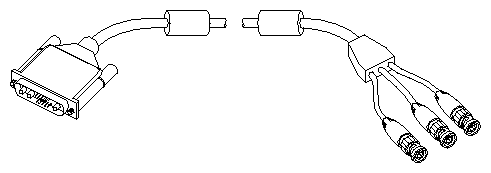 |
Table C-23. Monitor Extension Cable, Round, 75' Length, Shielded, 13W3 Hybrid Plugs at Each End of Cable
Part Number | Description |
|---|---|
018-8094-002 | Monitor extension cable, round, 75' length, shielded, 13W3 hybrid plugs at each end of cable. |
Figure C-23. Monitor Extension Cable, Round, 75' Length, Shielded, 13W3 Hybrid Plugs at Each End of Cable
|
Table C-24. Monitor Adapter Cable, Round, 1' Length, Shielded, 13W3 Hybrid Receptacle at One End, 3 BNC Plugs (RGB) at Other End
Part Number | Description |
|---|---|
018-0343-001 | Monitor adapter cable, round, 1' length, shielded, 13W3 hybrid receptacle at one end, 3 BNC plugs (RGB) at other end. |
Figure C-24. Monitor Adapter Cable, Round, 1' Length, Shielded, 13W3 Hybrid Receptacle at One End, 3 BNC Plugs (RGB) at Other End
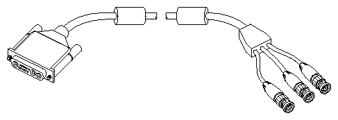 |
Table C-25. Monitor Adapter Cable, Round, 1' Length, Shielded, 13W3 Hybrid Plug at One End, 3 BNC Receptacles (RGB) at Other End
Part Number | Description |
|---|---|
018-0344-001 | Monitor adapter cable, round, 1' length, shielded, 13W3 hybrid plug at one end, 3 BNC receptacles (RGB) at other end. |
Figure C-25. Monitor Adapter Cable, Round, 1' Length, Shielded, 13W3 Hybrid Plug at One End, 3 BNC Receptacles (RGB) at Other End
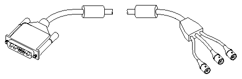 |
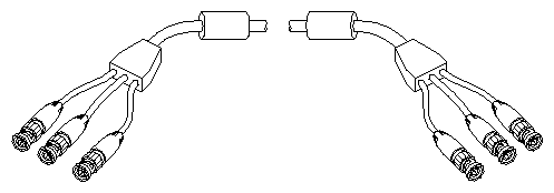
Table C-26. Monitor Extension Cable, Round, 75' Length, Shielded, 3 BNC Plugs (RGB) at Both Ends
Part Number | Description |
|---|---|
018-0275-003 | Monitor extension cable, round, 75' length, shielded, 3 BNC plugs (RGB) at both ends. |
The main keyboard (and mouse) connects to a dedicated port using a standard 30-foot cable. If a longer cable is required, order the 75-foot extension cable. Both of these cables are shown in Table C-27 and Table C-28.
Table C-27. Keyboard Extension Cable, Round, 30' Length, Shielded, 6-pin Circular Mini-DIN Plugs at Both Ends
Part Number | Description |
|---|---|
081-0345-001 | Keyboard extension cable, round, 30' length, shielded, 6-pin circular mini-DIN plugs at both ends. |
Figure C-27. Keyboard Extension Cable, Round, 30' Length, Shielded, 6-pin Circular Mini-DIN Plugs at Both Ends
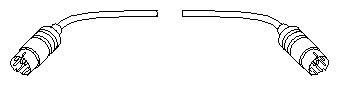 |
Table C-28. Keyboard Extension Cable, Round, 75' Length, Shielded, 6-pin Circular Mini-DIN Plugs at Both Ends
Part Number | Description |
|---|---|
081-0075-001 | Keyboard extension cable, round, 75' length, shielded, 6-pin circular mini-DIN plugs at both ends. |
Figure C-28. Keyboard Extension Cable, Round, 75' Length, Shielded, 6-pin Circular Mini-DIN Plugs at Both Ends
|
Table C-29 shows the rackmount system interrupt cable.
Table C-29. Rackmount System Interrupt Cable
Part Number | Description |
|---|---|
9290054 | Rackmount system interrupt cable, round, 35' length, 3.5 mm 3-conductor plugs at both ends, wired straight-through. |