This chapter describes the physical features of the Challenge/Onyx rackmount system. It provides an overview of the chassis components, a description of the I/O panel connectors, and information about board slot designations.
Table 1-1 through Table 1-16 provide an abbreviated tour of the rackmount chassis. The brief descriptions of the chassis components include the various in-house names they have had, as well as pointers to following sections that contain additional information. Table 1-17 through Table 1-32 give similar descriptions and pointers for all of the available boards.
Table 1-1. Rackmount Chassis Component - Challenge/Onyx Rackmount System
Product/Component Name | Description |
|---|---|
Challenge/Onyx rackmount system. Terminator was the rackmount chassis project name. | A system chassis that evolved from the 19-slot POWER Center. The physical dimensions are similar, but the internal arrangement of the rackmount chassis allows a significant increase in capacity. |
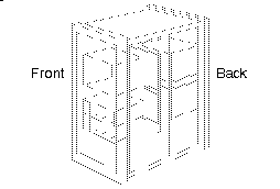
Table 1-2. Rackmount Chassis Component - Blower Assemblies
Product/Component Name | Description |
|---|---|
Blower Assemblies | Fans that pull air up through the chassis and exhaust it through the top of the system. There are two blower assemblies: front and rear. Each have their own access doors and can be removed and replaced independently. See Section 3.10.4, "Blower (Fan) Assembly." Note that the off-line switchers have their own fans and do not depend upon the blower assemblies for cooling. |
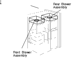
Table 1-3. Rackmount Chassis Component - Midplane
Product/Component Name | Description |
|---|---|
Midplane | A backplane that has bus connectors on both sides. The Challenge server midplane provides 15 Everest bus (Ebus) and 6 VMEbus connectors to cardcages 1 and 2. The Onyx graphics midplane has 11 Everest bus, 4 VMEbus, and 5 graphics bus connectors in cardcages 1 and 2. See Section 1.2, "Cardcages, Backplanes, and I/O Panels." |
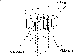
Table 1-4. Rackmount Chassis Component - Optional Backplane and Cardcage (Cardcage 3)
Product/Component Name | Description |
|---|---|
Optional backplane and cardcage (cardcage 3) | A third backplane and cardcage. In server systems, a 20-slot VMEbus backplane/cardcage is supplied. graphics machines are provided with 6 VMEbus slots and 12 graphics bus slots. See Section 1.2, "Cardcages, Backplanes, and I/O Panels." |
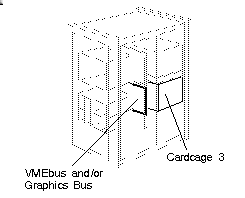
Table 1-5. Rackmount Chassis Component - Native VME™
Product/Component Name | Description |
|---|---|
Native VME™ | The VMEbus slots located on the system midplane. Note that the number of slots varies between the server and graphics midplanes (server midplane shown). See Section 1.2, "Cardcages, Backplanes, and I/O Panels." |
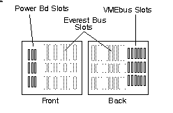
Table 1-6. Rackmount Chassis Component - Expansion VME
Product/Component Name | Description |
|---|---|
Expansion VME | The additional VMEbus slots available with the optional cardcage (Cardcage 3). See Section 3.11, "Optional Third Cardcage (Cardcage 3) and Power Supply Tray." |
Table 1-7. Rackmount Chassis Component - POWERmodules (Pay-as-you-go power supplies)
Product/Component Name | Description |
|---|---|
POWERmodules (Pay-as-you-go power supplies) | Combination of modular off-line switchers (OLSs) and power boards. Up to three 1900-watt OLSs can be installed, along with a variety of power boards. See Section 1.6, "Power Supplies and Power Distribution." |
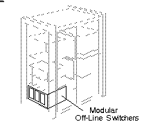
Table 1-8. Rackmount Chassis Component - Power Boards (System Controller, 505, 512, 512S)
Product/Component Name | Description |
|---|---|
Power boards (System Controller, 505, 512, 512S) | DC voltage convertors that step down the 48 volts output by the off-line switchers to voltage levels required by the buses and boards. Three configurations can be installed in cardcages 1 and 2, on backplane of cardcage 3, and on the SCSI backplane. See Section 1.6, "Power Supplies and Power Distribution." |
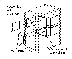
Table 1-9. Rackmount Chassis Component - SCSIBox 2 Drive Enclosure
Product/Component Name | Description |
|---|---|
SCSIBox 2 drive enclosure (Known internally as the "Stubbi" SCSI drive box) | Similar to a standard SCSI drive box, but can be installed in a shallower enclosure. Each box supports 4 full-height or 8 half-height drives. Accepts same types of Front Loading Devices (FLDs) as used with the POWER Center products, but uses a different sled assembly. One box is standard, a second identical box is available as an option. See Section 1.4, "SCSI Drive Boxes," and Section 3.6, "Storage Devices." |
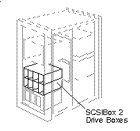
Table 1-10. Rackmount Chassis Component - Dual SCSI Buses
Product/Component Name | Description |
|---|---|
Dual SCSI buses | Two configurable SCSI buses that are distributed to each of the SCSI drive box backplanes. Note that all machines are cabled for the optional drive box. See Section 3.6, "Storage Devices." |
Table 1-11. Rackmount Chassis Component - Front-loading Device (FLD)
Product/Component Name | Description |
|---|---|
Front-loading Device (FLD) | A SCSI drive mounted on a P8 drive sled, that can be installed without any cabling. Connectors on the sled mate with a set of corresponding connectors located at the rear of the drive box. See Section 1.5, "Front-loading Devices," and Section 3.6, "Storage Devices." |
Table 1-12. Rackmount Chassis Component - Graphics I/O panel
Product/Component Name | Description |
|---|---|
Graphics I/O panel | This I/O panel is directly above the main I/O. It contains all of the interface ports to the first (or only) graphics board set. See Section 2.2. |
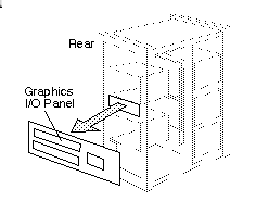
Table 1-13. Rackmount Chassis Component - Main I/O Panel (Fixed I/O)
Product/Component Name | Description |
|---|---|
Main I/O Panel (Fixed I/O) | This I/O panel is located between the upper and lower I/O panels for the two rear cardcages. The panel consists of the basic IO4 interfaces (video, keyboard, parallel port, powered and unpowered serial connectors). See Section 1.2, "Cardcages, Backplanes, and I/O Panels." |
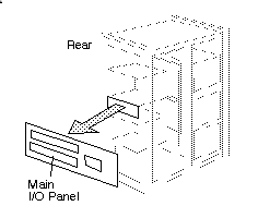
Table 1-14. Rackmount Chassis Component - System Status Panel
Product/Component Name | Description |
|---|---|
System Status Panel | A swing-out panel on the front of the system that provides status information, including CPU-use meters, and provides access to System Controller functions. It also contains the key switch for turning on and turning off the machine as well as for placing the machine in maintenance mode. See Section 1.3, "System Controller." |
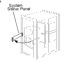
Table 1-15. Rackmount Chassis Component - System Controller
Product/Component Name | Description |
|---|---|
System Controller | An independent, microprocessor-controlled system monitor. Powers up and helps boot the system. Tracks and displays system status on the System Status Panel display and can shut down the system if necessary. See Section 1.3, "System Controller." |
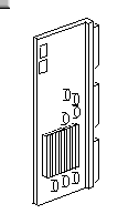
Table 1-16. Rackmount Chassis Component - ChallengeVault (T2 Expansion Rack)
Product/Component Name | Description |
|---|---|
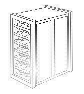
ChallengeVault (T2 Expansion Rack) | This expansion rack is based on the rack-mounted chassis and has identical physical dimensions. The expansion rack has 7 drive shelves capable of housing a maximum of 56 half-height drives. |
The following tables, Table 1-17 through Table 1-32, list various products and boards that are available for Challenge and Onyx rackmount systems.
Table 1-19. System Board - IO4 Board (IO4 base board)
Product/Board Name | Description |
|---|---|
IO4 Board (IO4 base board) | Basic Everest interface board. This board has network interfaces, parallel and serial ports, and two SCSI buses. Two additional Flat Cable Interfaces (FCIs) are used to connect to the VMEbus and to a graphics board set. See Section 2.4, "Everest I/O (POWERchannel 2) Subsystem." |
Table 1-20. System Board - Interface Modules (Mezzanine boards)
Product/Board Name | Description |
|---|---|
Interface Modules (Mezzanine boards) | These boards provide a variety of additional interfaces (including network interfaces) by mounting directly to the IO4 board. See Section 2.4, "Everest I/O (POWERchannel 2) Subsystem." |
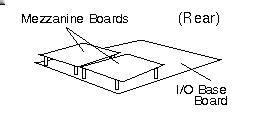
Table 1-21. System Board - SCSI Interface Module (S mezzanine)
Product/Board Name | Description |
|---|---|
SCSI Interface Module (S mezzanine) | The SCSI mezzanine board provides 3 SCSI-1 channels. Compatible with the WD95 SCSI controller chip. See Section 2.4, "Everest I/O (POWERchannel 2) Subsystem." |
Table 1-22. System Board - VME Channel Adapter Module (VCAM)
Product/Board Name | Description |
|---|---|
VME Channel Adapter Module (VCAM) | This board provides the interface between the Ebus and either the VMEbus or graphics bus. The VCAM mounts directly onto the IO4 board. This board is standard equipment and always installed on the first IO4 board. See Section 2.4, "Everest I/O (POWERchannel 2) Subsystem." |
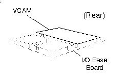
Table 1-23. System Board - Flat Cable Interface Modules (Long and Short)
Product/Board Name | Description |
|---|---|
Flat Cable Interface Modules (Long and Short) | These boards provide additional Flat Cable Interfaces. The Short FCI Interface Module has the same dimensions as the other mezzanine cards and supplies one FCI channel. The Standard FCI Interface Module is physically longer and provides two channels. Note that the long board cannot be used with a VCAM. See Section 2.4, "Everest I/O (POWERchannel 2) Subsystem." |
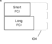
Table 1-24. System Board - Multi-net Interface Modules (AUI Ethernet, FDDI)
Product/Board Name | Description |
|---|---|
Multi-net Interface Modules (AUI Ethernet, FDDI) | These boards provide multiple ports to the supported networks. |
Table 1-25. System Board - Extender (Optional)
Product/Board Name | Description |
|---|---|
Extender (Optional) | These are passive boards that mount between the power boards and the midplane. Their purpose is to make the power boards more accessible by bringing them out from the midplane. These are not normally shipped on systems, but may be encountered occasionally in the field. |
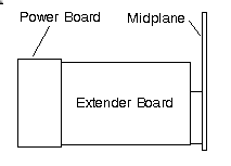
Table 1-26. System Board - IO4 Filter
Product/Board Name | Description |
|---|---|
IO4 Filter | This board provides noise suppression for signals going between the IO4 board and the main I/O panel. It contains a fuse. |
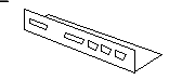
Table 1-27. System Board - Video Filter (EF7)
Product/Board Name | Description |
|---|---|
Video Filter (EF7) | This board supplies noise suppression for signals going between the graphics boards and the graphics I/O panel. It contains a fuse. |
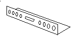
Table 1-28. System Board - SCSI Channel Adapter Boards
Product/Board Name | Description |
|---|---|
SCSI Channel Adapter Boards | Small boards that mount directly to the SCSI bus connectors on the IO4 board. Used to configure the SCSI bus for single-ended or differential operation. Color-coded: red = differential, green = single-ended. See Section 2.4, "Everest I/O (POWERchannel 2) Subsystem." |
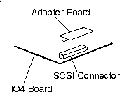
Table 1-29. System Board - RealityEngine2 Graphics Board Set (Mirage)/VTX Graphics Board Set
Product/Board Name | Description |
|---|---|
RealityEngine2 Graphics Board Set (Mirage) VTX Graphics Board Set | Multiple-board graphics sets that evolved from RealityEngine2. Composed of the following boards: one GE10 board, one Display Generator, and one, two, or four Raster Memory boards. (A three-board configuration is not supported.) VTX differs in that it uses the GE10V board instead of the GE10. See |
Table 1-30. System Board - Geometry Engine® (GE10)
Product/Board Name | Description |
|---|---|
Geometry Engine® (GE10) | Processes commands and data from the host. First stage in the graphics pipeline. |
Table 1-31. System Board - Raster MemoryTM (RM4)
Product/Board Name | Description |
|---|---|
Raster MemoryTM (RM4) | Scans and converts triangle data into pixel data. |
Table 1-32. System Board - Display GeneratorTM (DG2)
Product/Board Name | Description |
|---|---|
Display GeneratorTM (DG2) | Receives digital data from the Raster Memory and processes it to produce an analog signal for display. |
Figure 1-21 shows the components that are visible with the cabinet doors open.
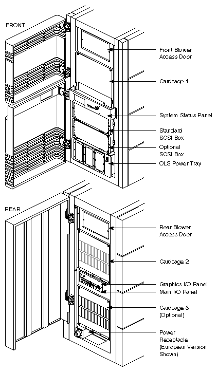
 | Note: The Onyx graphics system is shown in Figure 1-21. The Challenge server is identical except that the graphics I/O panel is replaced by a blank plate. |
The Everest midplane supports two cardcages: cardcage 1 at the front of the cabinet and cardcage 2 at the rear. Cardcage 1 houses the CPU boards, memory boards, and the System Controller board. These require no external cabling. Cardcage 1 also provides three slots for the power boards.
Cardcage 2 receives all of the I/O and graphics boards (if installed). All basic I/O connections from the first (or only) IO4 board are routed to the main I/O panel, located at the rear of the cabinet. All additional I/O connections are routed to connectors on the cardcage 2 I/O panel.
In graphics workstations, connections from the first (or only) RealityEngine2 or VTX board set are routed to the graphics I/O panel. Additional graphics boards are cabled to connectors on the cardcage 2 I/O panel.
An optional cardcage (cardcage 3) can be installed in the lower rear portion of the system cabinet. Servers can be fitted with a cardcage that provides 20 additional VMEbus slots. Graphics systems can be fitted with either the optional server cardcage or a second version that provides 6 VMEbus slots and 12 graphics bus slots. Cardcage 3 uses a conventional backplane that mounts to the rear of the cardcage. In a server, the rear of the backplane provides four slots for the power boards. In a graphics system, the rear of the backplane provides 6 slots for the power boards.
Table 1-33 lists the type and number of bus slots supported in each of the three server cardcages. Table 1-34 lists the graphics system's bus slots.
Table 1-33. Challenge Server System Cardcage Bus Slots
Buses Supported | Cardcage 1 | Cardcage 2 | Cardcage 3 |
|---|---|---|---|
Ebus | 7 slots | 8 slots | – |
VMEbus | – | 6 slots | 20 slots |
Power Board | 3 slots | – | 4 slots (backplane; 1 512 power board and 3 505 power boards) |
Table 1-34. Onyx Graphics System Cardcage Bus Slots
Buses Supported | Cardcage 1 | Cardcage 2 | Cardcage 3 |
|---|---|---|---|
Ebus | 6 slots | 5 slots | – |
VMEbus | – | 4 slots | 6 slots |
Graphics bus | – | 6 slots (5 plus 1 dedicated slot for GE10) | 12 slots |
Power Board | 4 slots | – | 6 slots (backplane; 1 512 power board and 5 505 power boards) |
The main I/O panel consists of a filter board and a set of I/O panel connectors that bring all of the basic I/O ports out from the IO4 board to the rear of the system cabinet. The ports available on the main I/O panel include the AUI Ethernet, keyboard, video, a parallel port, an RS-422 serial port, and both powered and unpowered RS-232 serial ports. The main I/O panel connector layout is shown in Figure 1-22.
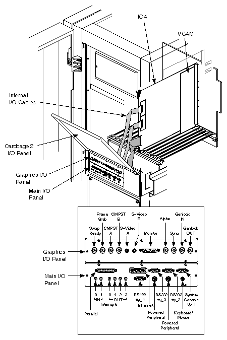
The graphics I/O panel consists of a filter board and a set of connectors that bring all of the VTX/RealityEngine2 video interfaces out from the graphics board set to the rear of the system cabinet. The ports available on the graphics I/O panel include S-Video channels A and B, the Frame Grab input port, Swap Ready, Genlock IN, Genlock OUT, Alpha sync, the video and external sync connectors, and red, green, and blue BNC connectors. The internal cabling and the external connector layout are shown in Figure 1-22.
| Note: On server systems, the graphics I/O panel is replaced with a blank filler panel. |
The System Controller board contains a microprocessor with battery-backed memory. It has a direct serial link to master the CPU board, as well as a series of sensors that monitor midplane voltages and cabinet temperature. The System Controller performs the following three basic tasks:
| Controls the system power-up, boot arbitration, and power-down processes. |
| |
| Provides passive monitoring during normal system operation. |
| |
| Acts as an independent system watchdog. |
|
The operator interface to the System Controller is called the System Status Panel. This consists of a 240 x 128-pixel LCD, four function buttons (Menu, Execute, Scroll Up, and Scroll Down), a key switch, and two LEDs (Power On and Fault). The function buttons and display mount on a hinged panel at the front of the cabinet. The System Controller function buttons and display are shown in Figure 1-23.
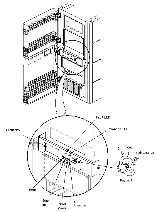
| Key Switch | The key switch has three positions: Off, On, and Maintenance (represented by an icon of a hand holding a wrench). The Off position shuts down voltages from the OLS to the rest of the system. (Note that the OLS is still powered on until the system breakers are shut off). The On position enables normal system operations. The Maintenance position enables the RESET and NMI functions. | |
| Menu Button | Pressing the Menu button will sequentially display the executable options. | |
| Execute Button | Pressing this button executes the option currently being displayed. | |
| Scroll Up/Scroll Down Buttons |
| |
| Power On LED |
| |
| Fault LED |
|
Refer to Appendix E, "System Controller Error and Status Messages," for a complete listing of all of the System Controller status and error messages.
There are two types of SCSI drive boxes available:
In its standard configuration, the rackmount system is shipped with a single SCSI drive enclosure (SCSI box) that is capable of holding four full-height or eight half-height SCSI devices.
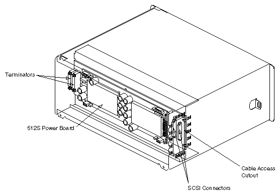
A second type of drive enclosure, called SCSIBox 2 (known internally as "Stubbi SCSI") is available as an option. The SCSIBox 2 does not have traditional internal power supplies. Instead, a 512S power board is mounted on the SCSI backplane to convert the incoming 48 VDC to +5 and +12 VDC for use by the drives. This design feature allows the SCSIBox 2to be installed in a shallower enclosure than a standard SCSI box (hence the nickname "Stubbi").
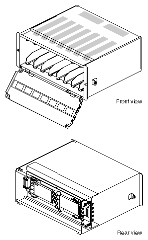
A SCSIBox 2 is shown in Figure 1-24. The rear view shows the 512S power board. Power supplies are further described in Section 1.6, "Power Supplies and Power Distribution."
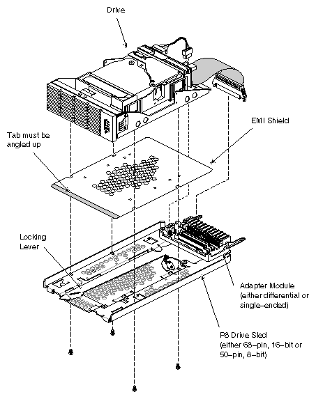
SCSI Front-loading Devices (FLDs) are the only type of storage drives that can be installed in the rackmount chassis. The storage devices used with the SCSIBox have what are known as P8 drive sleds. These drive sleds and corresponding drive trays are lower profile and more compact than those used with previous products.
A single delrin wheel on the drive tray is used to align the sled when it is installed. The self-aligning connectors are also an improvement over the previous design. The locking mechanism now has a lever, rather than a push button. The drive sleds also contain the logic used to adapt the mounted drive to either a differential or single-ended SCSI bus. Detailed explanations of the adapter logic and the supported configurations are provided in Chapter 3, "Installation."
 | Warning: If you install the EMI shield upside down in a P8 drive sled, there is a high risk of an electrical short in the drive. The EMI shield is copper and is coated on one side with clear plastic insulation. The insulated side of the shield must be placed against the drive. |
The EMI shield has a tab at the front that is angled. When the tab is angled up, the EMI shield is oriented correctly.
The following are some tips for verifying which side of the EMI shield is insulated and which is bare copper:
Rub each side with your fingernail. The copper side will scratch slightly. The plastic side will not show any marks.
Use an ohmmeter or continuity checker against each side.
Once you determine the insulated side of a particular EMI shield, you may wish to mark the shielded side for future reference (for example, using a permanent marking pen).
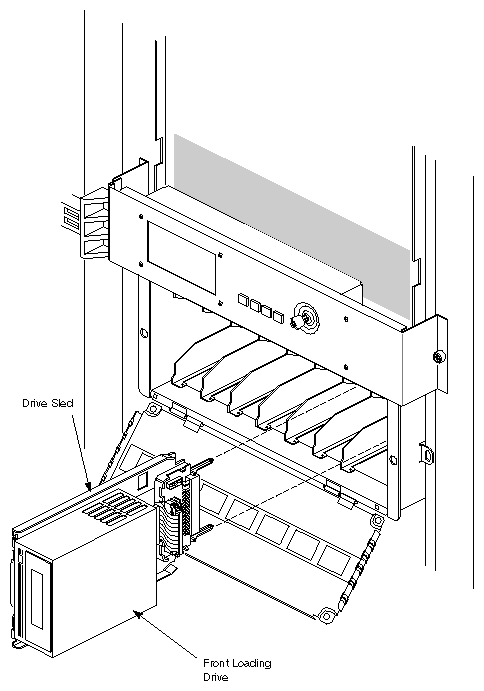
A drive and its sled are shown in Figure 1-25. Figure 1-26 shows a drive being installed in the SCSIBox.
The rackmount chassis supports a maximum of three 1900-watt off-line switchers (OLSs). The OLSs convert the AC input to 48 VDC at 37 amps and distribute the regulated voltage to the chassis midplane and backplane.
| Note: For a complete description of power requirements, including important information about branch-circuit wiring and grounding (earthing) requirements, see the Challenge/Onyx Site Preparation Guide (P/N 108-7040-020). There are additional considerations for systems that use the optional cardcage 3. See Section 3.11.1 through Section 3.11.3 in Chapter 3, "Installation." |
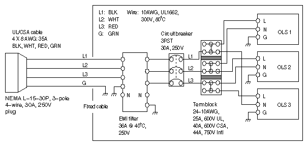
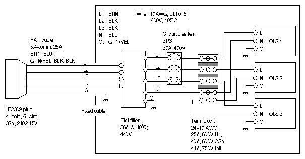
A rackmount chassis is wired in one of three different configurations, depending upon on the country to which the system is being sent and the power requirements of the system itself. See Figure 1-27 through Figure 1-29 for illustrations of the circuits.
Figure 1-27. Rackmount Chassis Wiring Diagram for 220VAC, 3-wire, 1-phase Power (U.S., Canada, and Japan)
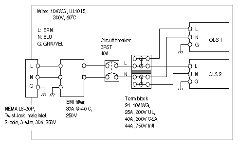 |
Figure 1-28. Rackmount Chassis Wiring Diagram for 220VAC, 4-wire, 3-phase Power (U.S., Canada, and Japan)
 |
The OLSs provide DC current to the midplane and backplane. In turn, DC regulators, installed on the CPU, Memory, VCAM, and GE10 boards, step down the midplane/backplane voltage for use by those boards.
| Note: The IO4 board draws -5V and -12V from the VCAM, and converts -5V to +1.5V for IBus termination voltage. |
Additional power boards supply the DC voltages required by the Ebus, graphics bus, and VMEbus. These power boards are available in different voltages and amperages, allowing the power distribution subsystem to be tailored to the voltage needs of a particular system configuration.
Five types of power board are available for the rackmount systems:
the System Controller board supplies 1.6 VDC to the Ebus
the 505 power board provides 5 VDC to the boards installed in Cardcage 3
the dual 505 (sometimes referred to as the 505x2), which supplies 5 VDC to boards installed in Cardcage 1 and Cardcage 2
the 512 power board generates both 5 and 12 VDC for use by the boards
the 512S power board supplies 5 and 12 VDC to the SCSI drive box backplane.
Table 1-35 shows configurations of OLSs and power boards for rackmount systems:
Table 1-35. OLS and Power Board Configurations for Rackmount Systems
System Configuration | OLSs Installed | Power Boards Installed |
|---|---|---|
Challenge | 2 | 3 (1 512, 1 dual 505, 1 System Controller) |
Onyx | 2 | 4 (1 512, 2 dual 505, 1 System Controller) |
Challenge with | 3 (requires 3-phase power) | 7 (2 512, 1 dual 505, 3 505, 1 System Controller) |
Onyx with | 3 (requires 3-phase power) | 10 (2 512, 2 dual 505, 5 505, 1 System Controller) |
Rackmount system are usually shipped with two OLSs. A third OLS, three-phase power, and an expanded OLS tray are required when the optional third cardcage (Cardcage 3) is installed in either the server or graphics systems.
The System Controller, 505, and 512 power boards are available in configurations that support both the midplane and the optional third cardcage. The midplane configuration mounts to an extender board and is installed in a Cardcage 1 board slot. The version designed for the optional Cardcage 3 is attached directly to the front of the backplane. (This requires removal of any SCSI drive boxes for access.) Both configurations of these power boards are shown in Figure 1-30.
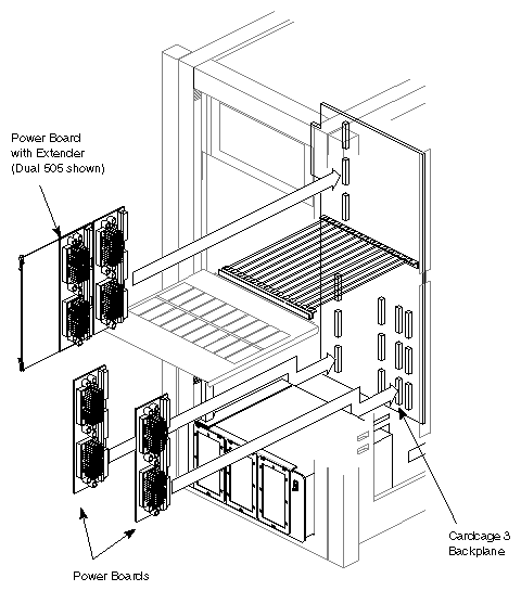

The video clip above shows how to install power boards on the front of the Cardcage 3 backplane behind the OLSs.
The 512S is the only power board that is not designed to attach to either the midplane or the backplane. The 512S mounts directly on the SCSI backplane of the SCSIBox 2 (see Figure 1-31).