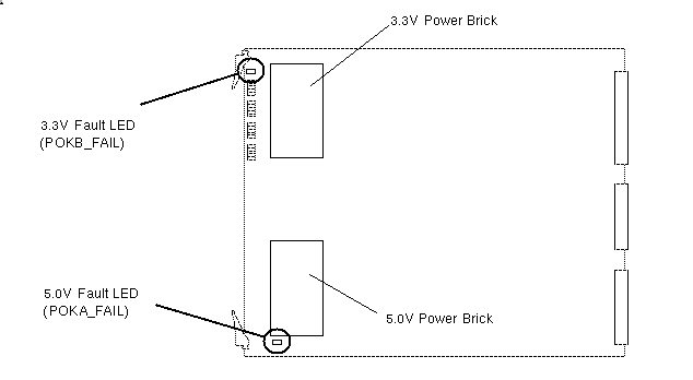
The IP19 has two power bricks that step down the 48 volts from the midplane/backplane to 5.0 and 3.3 volts. Each brick has a corresponding power fault LED, as shown in Figure F-1.
 | Note: The LEDs are red and indicate a fault when lit. |
The IP19 board has a total of 24 fault indicators (see Figure F-2). A bank of six LEDs is assigned to each processor. Each bank displays 44 status values and 15 error values. The values are displayed by the banks as a binary number, with the most significant bit represented by the topmost LED (as viewed from the front of the cardcage). The status values are displayed as the system progresses through the power-on tests. If a constant value is displayed, convert the binary value to a decimal number and use Section F.1.2, "LED Status Codes," to identify the status message. Each status message is displayed as a constant value and has the prefix "PLED" (PROM LED) attached to its description.
If a fatal error prevents the power-on tests from completing, the LEDs will flash the error value until the system is powered down or reset. Error messages have the prefix "FLED" (Flashing LED) attached to their descriptions. Section F.1.3, "LED Error Codes" lists the error codes.
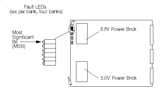
These binary error codes apply to all of the microprocessors resident on the board. IP19 boards are configured with all four banks of LEDs, regardless of the number of microprocessors installed. See Table F-1.
.
Table F-1. IP19 Board Test Status LED Codes
LED Pattern Displayed | Description |
|---|---|
MSB X O O O O O LSB | PLED_CLEARTAGS (1) - Clearing the primary data cache tags. |
MSB O X O O O O LSB | PLED_CKCCLOCAL (2) - Testing CC chip local registers. |
MSB X X O O O O LSB | PLED_CCLFAILED_INITUART (3) - Failed the local test but trying to initialize UART. |
MSB O O X O O O LSB | PLED _CCINIT1 (4) - Initializing the CC chip local registers. |
MSB X O X O O O LSB | PLED_CKCCCONFIG (5) - Testing the CC chip config registers (requires usuable bus to pass). If test hangs, usually means bus has failed. Check oscillator. |
MSB O X X O O O LSB | PLED_CCLFAILED_INITUART (6) - Failed the config reg test but trying to initialize UART. |
MSB X X X O O O LSB | PLED_NOCLK_INITUART (7) - CC clock not running. Init UART anyway. |
MSB O O O X O O LSB | PLED_CCINIT2 (8) - Initializing the CC chip config registers. |
MSB X O O X O O LSB | PLED_UARTINIT (9) - Initializing the CC chip UART. If test hangs, usually means bad UART clock. Check connections to system Controller. |
MSB O X O X O O LSB | PLED_CCUARTDONE (10) - Finished initializing the CC chip UART. |
MSB X X O X O O LSB | PLED_CKACHIP (11) - Testing the A chip registers. |
MSB O O X X O O LSB | PLED_AINIT (12) - Initializing the A chip. |
MSB X O X X O O LSB | PLED_CKEBUS1 (13) - Checking the Ebus with interrupts. |
MSB O X X X O O LSB | PLED_SCINIT (14) - Initializing the System Controller. |
MSB X X X X O O LSB | PLED_BMARB (15) - Arbitrating for a bootmaster. |
MSB O O O O X O LSB | PLED_BMASTER (16) - This processor is the bootmaster. |
MSB X O O O X O LSB | PLED_CKEBUS2 (17) - Running second Ebus test. Run only by the bootmaster. |
MSB O X O O X O LSB | PLED_POD (18) - Setting up this CPU slice for POD mode. |
MSB X X O O X O LSB | PLED_PODLOOP (19) - Entering POD loop. |
MSB O O X O X O LSB | PLED_CKPDCACHE1 (20) - Checking the primary data cache. |
MSB X O X O X O LSB | PLED_MAKESTACK (21) - Creating a stack in the primary data cache. |
MSB O X X O X O LSB | PLED_MAIN (22) - Jumping into C code -- calling main. |
MSB X X X O X O LSB | PLED_CKIAID (23) - Checking IA and ID chips on master IO4. |
MSB O O O X X O LSB | PLED_CKEPC (24) - Checking EPC chip on master IO4. |
MSB X O O X X O LSB | PLED_IO4INIT (25) - Initializing the IO4 PROM. |
MSB O X O X X O LSB | PLED_NVRAM (26) - Getting NVRAM variables. |
MSB X X O X X O LSB | PLED_FINDCONS (27) - Checking the path to the EPC chip, which contains the console UART. |
MSB O O X X X O LSB | PLED_CKCONS (28) - Testing the console UART. |
MSB X O X X X O LSB | PLED_CONSINIT (29) - Setting up the console UART. |
MSB O X X X X O LSB | PLED_CONFIGCPUS (30) - Configuring out CPUs that are disabled. |
MSB X X X X X O LSB | PLED_CKRAWMEM (31) - Checking raw memory (running Board Internal Self-Test [BIST]. |
MSB O O O O O X LSB | PLED_CONFIGMEM (32) - Configuring memory. |
MSB X O O O O X LSB | PLED_CKMEM (33) - Checking configured memory. |
MSB O X O O O X LSB | PLED_WTCONFIG (34) - Writing evconfig structure: The bootmaster CPU writes the entire array. The slave CPUs only write their own entries. |
MSB X X O O O X LSB | PLED_LOADPROM (35) - Loading IO4 PROM. |
MSB O O X O O X LSB | PLED_CKSCACHE1 (36) - First pass of secondary cache testing. Tests the scache like a RAM. |
MSB X O X O O X LSB | PLED_CKPICACHE (37) - Checking the primary instruction cache. |
MSB O X X O O X LSB | PLED_BADEAROM (38) - The EAROM associated with the CPU is corrupt and couldn't be repaired. |
MSB X X X O O X LSB | PLED_CKSCACHE2 (39) - Checking secondary data cache writeback mechanism. |
MSB O O O X O X LSB | PLED_CKBT (40) - Check the bus tags. |
MSB X O O X O X LSB | PLED_BTINIT (41) - Clearing the bus tags. |
MSB O X O X O X LSB | PLED_CKPROM (42) - Checksumming the I/O PROM. |
MSB X X O X O X LSB | PLED_INSLAVE (43) - This CPU is entering slave mode. |
MSB O O X X O X LSB | PLED_PROMJUMP (44) - Jumpering to the I/O PROM. |
MSB X O X X O X LSB | PLED_SLAVEJUMP (45) - A slave is jumping to the IO4 PROM slave code. |
Table F-2 lists the IP19 board power-on test failure LED codes.
Table F-2. IP19 Board Power-on Test Failure LED Codes
LED Pattern Displayed X=Lit | Description (Flashing Value Displayed) |
|---|---|
MSB O X X X O X LSB | FLED_CANTSEEMEM (46) - Flashed by slave processors if they take an exception while trying to write their evconfig entries. Often means that processor is getting D-chip parity errors. |
MSB X X X X O X LSB | FLED_NOUARTCLK (47) - The CC UART clock is not running. No System Controller access possible. |
MSB O O O O X X LSB | FLED_INPOSSIBLE1 (48) - System fell through an unreturning subroutine (shouldn't be possible). |
MSB X O O O X X LSB | FLED_DEADCOP1 (49) - Coprocessor 1 is dead (no error does not mean coprocessor is good). |
MSB O X O O X X LSB | FLED_CCCLOCK (50) - Cache controller (CC) clock is not running. |
MSB X X O O X X LSB | FLED_CCLOCAL (51) - Failed CC local register tests. |
MSB O O X O X X LSB | FLED_CCCONFIG (52) - Failed CC config register tests. |
MSB X O X O X X LSB | FLED_ACHIP (53) - Failed A chip register tests. |
MSB O X X O X X LSB | FLED_BROKEWB (54) - By the time this CPU arrived at bootmaster arbitration barrier, the rendezvous time had passed. CPU is running too slowly, the ratio of the bus clock rate to CPU clock rate is too high, or a bit in the CC clock is stuck on. |
MSB X X X O X X LSB | FLED_BADCACHE (55) - CPU's primary data cache test failed. |
MSB O O O X X X LSB | FLED_BADIO4 (56) - IO4 board is bad (can't get to console). |
MSB X O O X X X LSB | FLED_UTLBMISS (57) - Took a TLB refill exception. |
MSB O X O X X X LSB | FLED_XTLBMISS (58) - Took an extended TLB refill exception. |
MSB X X O X X X LSB | FLED_CACHE (59) - Unused. |
MSB O O X X X X LSB | FLED_GENERAL (60) - Took a general exception. |
MSB X O X X X X LSB | FLED_NOTIMPL (61) - Took an unimplemented exception. |
MSB O X X X X X LSB | FLED_ECC (62) - Took a cache error exception. |
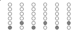
When the Power-on Diagnostics (POD) run, a pair of LEDs from each bank of processor LEDs flashes alternately. After the POD finishes and the system enters the PROM monitor, the LEDs on the bootmaster CPU will display a fixed value (binary 18). All other slave processors will loop on a pattern waiting for a command (see Figure F-3).
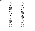
The bootmaster CPU will loop on the pattern shown in Figure F-4 when polling the CC UARTs.
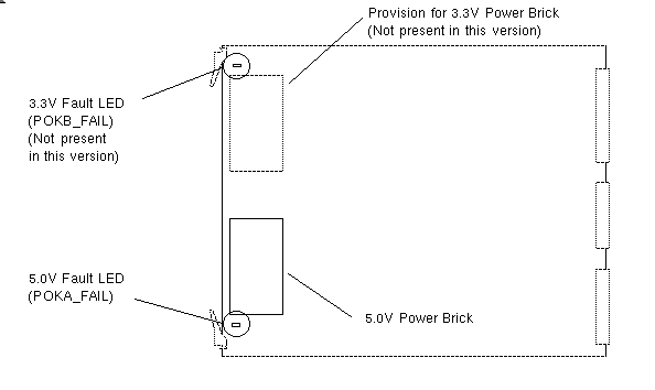
The MC3 board currently has a single +5.0-volt power brick and a corresponding fault indicator. Later versions of this board may have an additional +3.3V brick, as shown in Table F-3 and Figure F-5.
| Note: The LEDs are red and indicate a fault when lit. |
Table F-3. MC3 Board Fault LEDs
LED Reference Designation | Color / Meaning When Lit | Description |
|---|---|---|
B4P2 (POKA_FAIL) | Red - Fault | Bad 5.0V power brick |
N8P2 (POKB_FAIL) | Red - Fault | Bad 3.3V power brick |
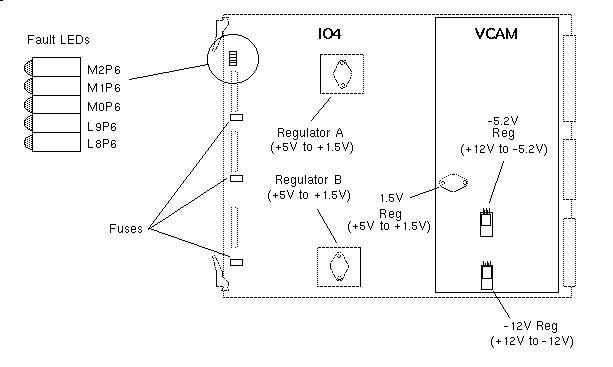
The IO4 board has a single bank of five LEDs and two secondary regulators. These regulators convert +5 volts to +1.5 volts (see Table F-4 and Figure F-6). The IO4 also has three replaceable fuses, as shown in Figure F-6.
The VCAM board has three secondary regulators; +1.5, -12, and -5.2V.
| Note: All LEDs are red and indicate a fault when lit. The bottom three LEDs provide power fault indications for the attached VMEbus Channel Adapter Module (VCAM). The VCAM fault LEDs are mounted on the IO4 board because the dimensions of the VCAM would make on-board LEDs extremely difficult to read. These LEDs are unlit when no VCAM is installed. |
Table F-4. IO4 Board Fault LEDs
LED Reference Designation | Color / Meaning When Lit | Description |
|---|---|---|
M2P6 (POKB_FAIL) | Red - Fault | Bad 1.5V regulator A (near top) on the IO4 board |
M1P6 (POKB_FAIL) | Red - Fault | Bad 1.5V regulator B (near bottom) on the IO4 board |
M0P6 (POKB_FAIL) | Red - Fault | Bad 1.5V regulator on the VCAM |
L9P6 (POKA_FAIL) | Red - Fault | Bad +12V to -5.2V regulator on the VCAM |
L8P6 (POKA_FAIL) | Red - Fault | Bad +12.0V to -12.0V regulator on the VCAM |
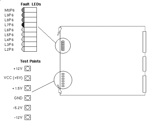
The RMT_VCAM board has a bank of nine fault LEDs that flag power faults stemming from the Cardcage 3 backplane, the System Controller, and the three regulators on the RMT_VCAM itself. There are also six test points corresponding to the monitored voltages (see Table F-5 and Figure F-7).
| Note: The voltage levels of the three on-board voltage regulators are monitored by two sets of LEDs: the three red LEDs and the bottom three amber LEDs. The red LEDs light when a voltage error is sensed and remain lit until the system is reset. The amber LEDs provide a "hot" measurement and light only when an error in the monitored voltage levels is currently present. |
Table F-5. Remote VCAM Fault LEDs
LED Reference Designation | Color / Meaning When Lit | Description |
|---|---|---|
M0P6 | Red - Fault | Bad +1.5V regulator on the RMT_VCAM |
L9P6 | Red - Fault | Bad -5.2V regulator on the RMT_VCAM |
L8P6 | Red - Fault | Bad -12V regulator on the RMT_VCAM |
L7P6 | Green - Good | 5V input (V5_AUX) from System Controller to RMT_VCAM (should always be on) |
L6P6 | Amber - Fault | Bad +12V input from the backplane |
L5P6 | Amber - Fault | Bad +5V input (VCC) from the backplane |
L4P6 | Amber - Fault | Bad +1.5V regulator on the RMT_VCAM |
L3P6 | Amber - Fault | Bad -5.2V regulator on the RMT_VCAM |
L2P6 | Amber - Fault | Bad -12V regulator on the RMT_VCAM |
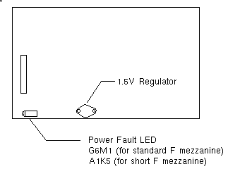
Both F mezzanine boards (long F mezz and short F mezz) have a 5V-to-1.5V regulator, identical to those on the IO4 and VCAM. Each F mezz board also has a single, red power fault LED, as shown in Figure F-8. The LED lights when the voltage level is out of range.
The S mezzanine board (not shown) has no regulators but has three removable fuses.
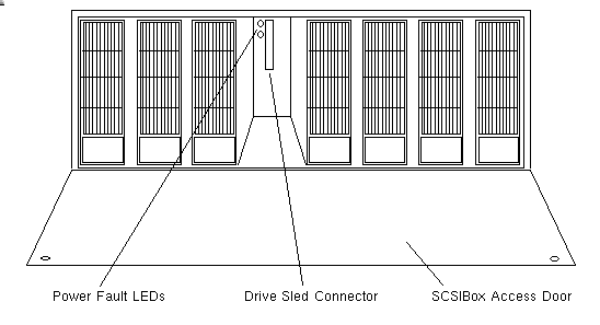
There is a +5V and a +12V power fault LED located behind each drive in the SCSIBox. Both LEDs are green and are lit during normal operation (see Figure F-9).