The Everest products support many types of SCSI protocols, resulting in a wide variety of SCSI channel configurations. This appendix introduces the supported SCSI protocols for Challenge/Onyx products, defines the components in a SCSI channel, and explains how to configure and label a SCSI channel.
SCSI devices continue to evolve with higher bus bandwidths, faster data transfer rates, and channels with longer cables and more devices.
A protocol establishes a SCSI bus's bandwidth, type, and data transfer rate. These factors are dependent on each other. For example, a 16-bit SCSI peripheral typically transfers more data at a faster rate than an 8-bit SCSI peripheral.
An 8-bit bus provides up to 8 SCSI IDs, and a 16-bit bus provides up to 16 SCSI IDs. Since a SCSI bus controller uses the first SCSI ID (ID #0), 8-bit buses use seven SCSI IDs for devices, and 16-bit buses use 15 SCSI IDs.
A SCSI bus type is either single-ended or differential. A single-ended SCSI peripheral uses inexpensive, open-collector-wired, OR busing configurations that use a signal comparison to ground. This limits the distance the signal can be driven because of noise considerations.
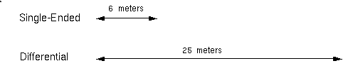
Differential SCSI peripherals use differential drivers and receivers with built-in hysteresis to provide improved signal noise immunity so that the bus can be driven to greater lengths, as shown in Figure D-1. Single-ended and differential SCSI peripherals use incompatible integrated circuitry and cannot be mixed on a bus.
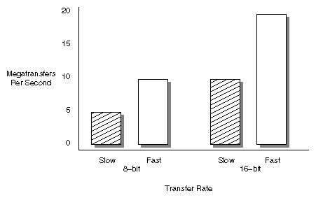
Data transfer rates are either slow or fast, measured in megatransfers per second. Megatransfers are the number of million operations per bus cycle. An operation is either 8- or 16-bit in size. Megatransfers are based on a bus's burst data rate. Data transfer rates are dependent on the bus bandwidth. See Figure D-2.
The System Controller negotiates independently with the devices on a bus to establish the acceptable transfer rate of each device, allowing a mix of fast and slow devices on the same bus.
These guidelines reflect the dependencies between SCSI bus bandwidths, types, and data transfer rates. Follow these guidelines help to minimize inconsistent or inoperable SCSI buses:
Install single-ended and differential devices on separate buses.
When calculating SCSI bus length, include all cable length inside devices, components, and chassis.
A SCSI channel can include a mix of these components:
a board that generates the signal
all cabling from the start to the end of a channel
all converters and adapters in the cable path
all SCSI devices connected to the channel
a terminating device at the end of the channel
See Table D-1 through Table D-8 for a descriptions of the typical components in a Challenge/Onyx SCSI bus, and Figure D-11 for an overview of the default chassis SCSI implementations for the rackmount chassis.
This section describes the components of a SCSI channel and illustrates the location of the components for default chassis configurations.
Table D-1. SCSI Channel Component - IO4 Board
SCSI Channel Component | Description |
|---|---|
Figure D-3 IO4 Board | IO4 board: an IO4 board provides SCSI bus signals for up to 8 SCSI buses. SCSI buses 0 and 1 are available directly on the IO4 board. Buses 2-4 require a mezzanine board attached to the lower mezzanine connector on the IO4 board, and buses 5-7 require a second mezzanine board attached to the upper mezzanine connector.
IO4 boards support all SCSI protocols and use an adapter board to select the desired protocol for each bus.
Several IO4 boards may reside in a system. |
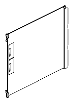
Table D-2. SCSI Channel Component - SCSI Mezzanine Board
SCSI Channel Component | Description |
|---|---|
Figure D-4 SCSI Mezzanine Board | SCSI mezzanine board: a SCSI mezzanine board attaches to an IO4 board, up to 2 mezzanine boards for each IO4 board. Each SCSI mezzanine board supports 3 SCSI buses. On the inner connectors, two buses use differential protocol only, and on the outer connector, the bus is selectable as either single-ended or differential by using a channel adapter board.
The first mezzanine board provides SCSI buses 2-4, with bus 2 on the outer center connector. The second mezzanine board provides SCSI buses 5-7, with bus 5 on the outer center connector. |
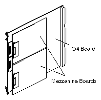
Table D-3. SCSI Channel Component - Channel Adapter Board
SCSI Channel Component | Description |
|---|---|
Figure D-5 Channel Adapter Board | Channel adapter board: a channel adapter board adapts a SCSI bus for either single-ended or differential protocol. Channel adapter boards attach directly to an IO4 board or to the outer connector on a SCSI mezzanine board. These are sometimes referred to as "personality modules." |

Table D-4. SCSI Channel Component - SCSI Bulkhead (Deskside Version Shown)
SCSI Channel Component | Description |
|---|---|
Figure D-6 SCSI Bulkhead (Deskside Version Shown) | SCSI bulkhead (deskside version shown): a SCSI bulkhead supplies a blind-pluggable receptacle to each SCSI device bay in a SCSI box. Each receptacle provides up to two SCSI channels, selectable using a drive adapter board.
The bulkhead also provides connectors at the end of the channels for termination.
Several different SCSI bulkheads exist depending on the chassis involved. |
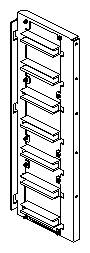
Table D-5. SCSI Channel Component - Drive Adapter Board, 50-pin
SCSI Channel Component | Description |
|---|---|
Figure D-7 Drive Adapter Board, 50-pin | Drive adapter board, 50-pin: a drive adapter board selects one of the two possible SCSI channels delivered to each drive bay. A drive adapter board resides on a drive sled and provides blind-pluggable connection between a SCSI device and the SCSI bulkhead. The 50-pin adapter board is used for drives that use a 50-pin cable, which are typically single-ended devices. |
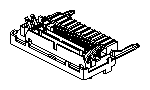
Table D-6. SCSI Channel Component - Drive Adapter Board, 68-pin
SCSI Channel Component | Description |
|---|---|
Figure D-8 Drive Adapter Board, 68-pin | Drive adapter board, 68-pin: a drive adapter board selects one of the two possible SCSI channels delivered to each drive bay. A drive adapter board resides on a drive sled and provides blind-pluggable connection between a SCSI device and the SCSI bulkhead. The 68-pin adapter board is used for drives that use a 68-pin cable, which are typically differential devices. |
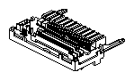
Table D-7. SCSI Channel Component - SCSI Device (CD Player Shown)
SCSI Channel Component | Description |
|---|---|
Figure D-9 SCSI Device (CD Player Shown) | SCSI device (CD player shown): a SCSI device is a storage and retrieval mechanism that uses the SCSI specification. Typical single-ended devices allow a maximum of 7 devices on a short channel. Newer differential devices have up to 15 devices on much longer channels. |
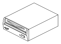
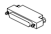
Table D-8. SCSI Channel Component - SCSI Terminator
SCSI Channel Component | Description |
|---|---|
Figure D-10 SCSI Terminator | SCSI terminator: a SCSI terminator resides at the end of a SCSI channel and terminates the signals. A SCSI channel will not work unless it is properly terminated. |
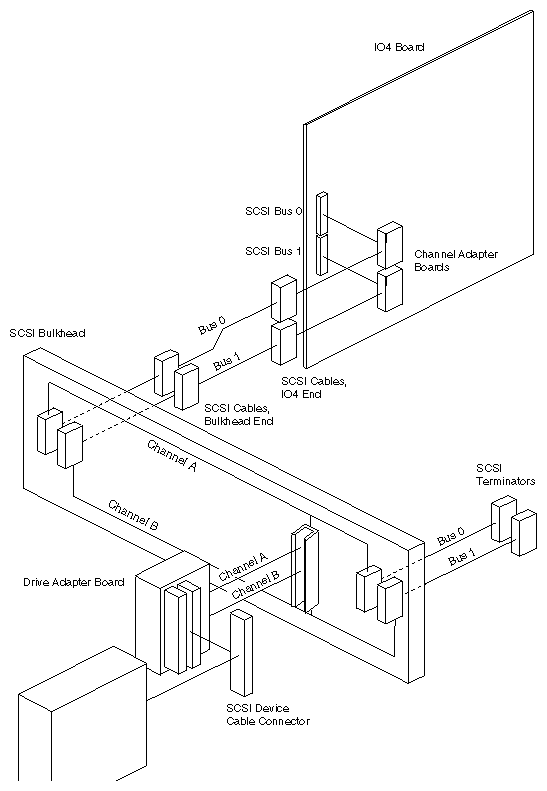
All components from the start to the end of a SCSI channel must be set to the same protocol (single-ended, differential, data transfer rate). Components are set to a SCSI protocol using one of several mechanical methods, such as selecting specific jumpers and connectors. By using jumpers and connectors, many different SCSI devices can use the same basic mechanical design within several chassis.
To configure a SCSI channel:
Verify the type of SCSI protocol required.
Identify each component in the SCSI channel using the chart in Section D.2, "Identifying SCSI Channel Components."
Obtain any missing components.
Configure all components to the desired protocol as shown in Section D.3.1, "Configuring IO4 and SCSI Mezzanine Boards," through Section D.3.3, "Configuring a SCSI Bus Terminator."
This section provides procedures for SCSI channel components that can be configured:
IO4 and mezzanine boards
channel adapter boards
SCSI cables
drive adapter boards
IO4 boards and SCSI mezzanine boards require no configuration other than selecting the type of channel adapter board to use with SCSI buses 0, 1, 2, and 5. Buses 3, 4, 6, and 7 are fixed for differential SCSI only. See Figure D-12 for the position of the bus connectors.
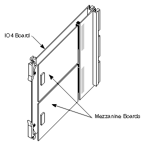
IO4 boards are shipped from the factory with a single-ended channel adapter board on SCSI bus 0, and a differential channel adapter board on SCSI bus 1. Each system also includes spare adapters to modify this configuration. By default, SCSI buses 0 and 1 support internal devices. The two SCSI bus signals are routed through the chassis using two SCSI channels, which are available at all drive bays. This arrangement allows a mix of single-ended and differential devices within the same drive box.
SCSI mezzanine boards are shipped from the factory with both a single-ended and differential channel adapter board for use with the first SCSI bus on the mezzanine board. The second and third mezzanine SCSI channels are fixed as differential only.
Channel adapter boards determine the protocol of a SCSI channel leaving an IO4 or SCSI mezzanine board. There are two types of channel adapter board, which are color-coded to simplify identification: green for single-ended protocol and red for differential protocol.
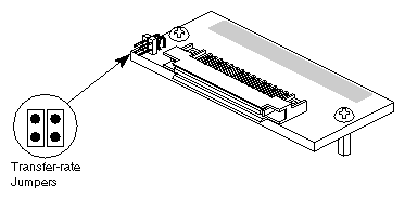
Single-ended channel adapter boards include jumpers for setting the data transfer rate of the channel to either slow or fast. Table D-9 describes the jumper settings.
Table D-9. Setting the Single-ended SCSI Bus Speed (Transfer-rate Jumpers)
Speed | Use | Jumper Setting |
|---|---|---|
Slow | Peripherals outside chassis | No jumpers installed |
Fast | Peripherals inside chassis | Both jumpers installed |
Figure D-13 shows the location and orientation of the transfer-rate jumpers on the single-ended channel adapter board:
Cables do not have any special jumpers or other method to configure a specific protocol. However, a cable must meet the electrical specifications and length limitations of the protocol. Figure D-1 shows the maximum allowable length of a channel for each protocol. Most of the total channel length is taken up by the cabling between devices or chassis.
 | Note: A cable sold for use with one SCSI configuration may not be appropriate for other SCSI configurations. When in doubt, use a shorter cable. |
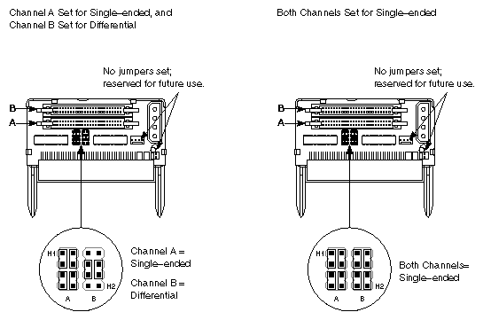
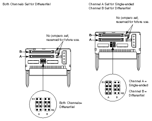
Drive adapter boards must match the SCSI device cable and the SCSI channel protocol.
To match the cabling of a SCSI device, check the type of connector on the SCSI device's cable. For cables with 50-pin connectors, use a 50-pin drive adapter board as shown in Figure D-14. For cables with 68-pin connectors, use a 68-pin drive adapter board as shown in Figure D-15.
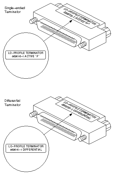
SCSI terminators must be matched to the protocol of the SCSI channel. There are two different terminators: one for single-ended protocol and one for differential protocol. These terminators are visually identical except for the manufacturing part numbers. See Table D-10 and Figure D-16.
Table D-10. SCSI Bus Terminator Part Numbers
Component | SGI Part Number | Distinguishing Marks |
|---|---|---|
Single-ended Terminator | 9660008 | AMP 869516-1 ACTIVE |
Differential Terminator | 9660006 | AMP 869515-1 |
 | Warning: Never use a single-ended SCSI terminator on a differential channel. Connecting a single-ended terminator to a differential channel shorts power to ground. |
This section describes the SCSI channel labels for individuals who need to determine the configuration of a SCSI channel or modify the SCSI labels for a rackmount chassis.
To simplify SCSI channel identification, labels are on the IO panel SCSI connectors, cables, SCSI devices, SCSIBoxes, and terminators. Depending on the component in question, a label may provide:
a bus number to identify the I/O board that provides the SCSI signal
a channel protocol to identify whether the channel is single-ended or differential
a number to identify the channel inside a SCSIBox that supplies the SCSI bus, either A or B
To determine the protocol of a SCSI channel with missing or unreadable labels, check the configuration of one or more components on the channel using the data in Section D.3, "Configuring a SCSI Channel." The easiest component to reach is the drive adapter board. Also, a channel adapter board is color-coded to simplify identification. Single-ended channel adapter boards are green, and differential channel adapter boards are red.
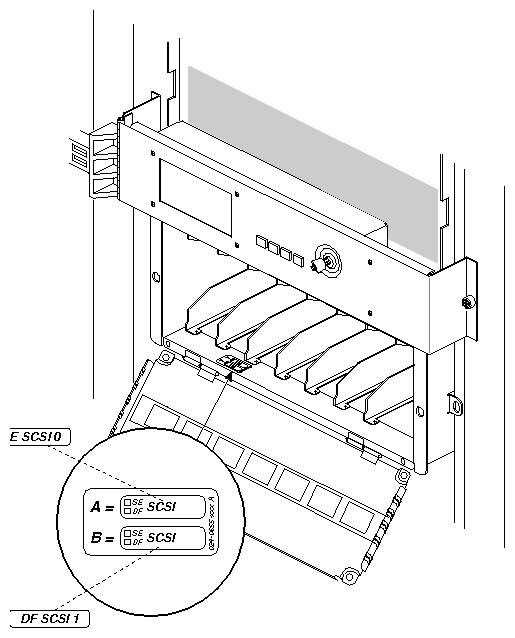
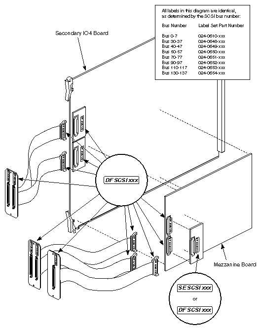
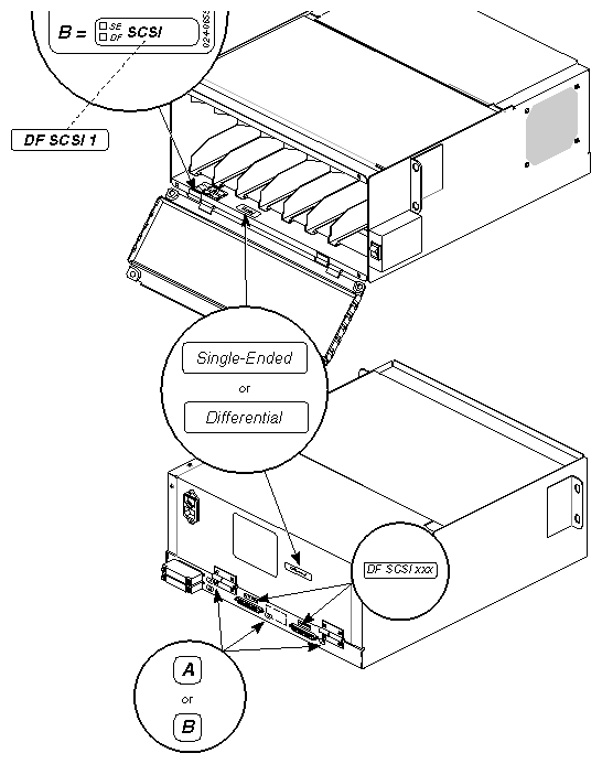
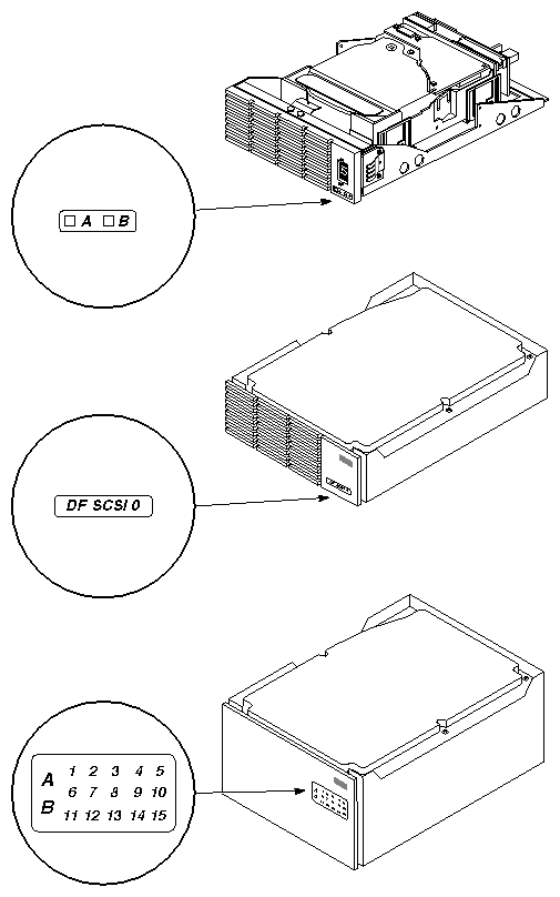
See Figure D-17 and Table D-11 through Table D-22 for descriptions of rackmount SCSI channel labels and their locations. See also Figure D-30 through Figure D-33.
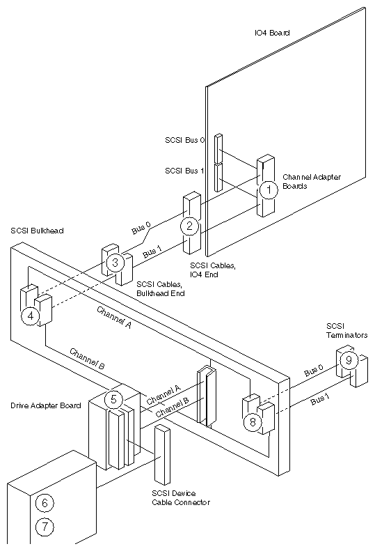
Table D-11. Channel Adapter Board Label
Key | Description | Placement Procedure |
|---|---|---|
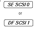
1 | Channel adapter board label; identifies SCSI protocol (SE or DF) and bus number (0-7); SE SCSI 0 label is part number 024-0637-xxx; DF SCSI 1 label is part number 024-0640–xxx; secondary SCSIBoxes are labeled from label set part numbers 024–0610–xxx through 024–0654–xxx. | Select label based on the slot and bus number of the IO board. For example, in the default configuration bus 0 on an IO4 board in slot 13 gets the label SE SCSI 130. Place label on flat face of the cable connector, aligning the bottom of the text along the inner, long edge of the connector. |
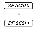
Table D-12. SCSI Cable Label, Board End
Key | Description | Placement Procedure |
|---|---|---|
2 | SCSI cable label, board end; identifies SCSI protocol (SE or DF) and the bus number (0-7); SE SCSI 0 label is part number 024-0637-xxx; DF SCSI 1 label is part number 024-0640–xxx; secondary SCSIBoxes are labeled from label set part numbers 024–0610–xxx through 024–0654–xxx. | fig on the slot and bus number of the I/O board. For example, in the default configuration bus 0 on an IO4 board in slot 13 gets the label SE SCSI 130. Place label on flat face of the cable connector, aligning the bottom of the text along the inner, long edge of the connector. |
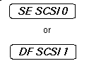
Table D-13. SCSI Cable Label, Bulkhead End
Key | Description | Placement Procedure |
|---|---|---|
3 | SCSI cable label, bulkhead end; identifies SCSI protocol (SE or DF) and the bus number (0-7); SE SCSI 0 label is part number 024-0637-xxx; DF SCSI 1 label is part number 024-0640–xxx; secondary SCSIBoxes are labeled from label set part numbers 024–0610–xxx through 024–0654–xxx. | Select label based on the slot and bus number of the I/O board. For example, in the default configuration bus 0 on an IO4 board in slot 13 gets the label SE SCSI 130. Place label on flat face of the cable connector, aligning the bottom of the text along the inner, long edge of the connector. |
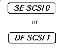
Table D-14. Bulkhead SCSI Cable Connector
Key | Description | Placement Procedure |
|---|---|---|
4 | Bulkhead SCSI cable connector; in early revisions, no markings for channel connectors A and B; channel A is the bottom connector, and channel B is the top connector; in later revisions, A and B markings are included on the bulkhead. | None required. |
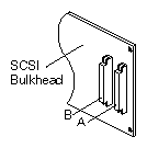
Table D-15. Drive Adapter Board Markings for SCSI Channels A and B
Key | Description | Placement Procedure |
|---|---|---|
5 | Drive adapter board markings for SCSI channels A and B; on 50-pin adapter boards, the two selectable connectors are marked JA1 and JB1; on 68-pin adapters, the connectors are marked J1_A and J1_B. | None required. |
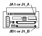
Table D-16. SCSI Device Label for Devices with Large Front Bezels
Key | Description | Placement Procedure |
|---|---|---|
6a | SCSI device label for devices with large front bezels; identifies the SCSI channel (A or B), and the device ID number (1-15); part number 024-0632-xxx. | Place label on the inner face of the drive door, along the hinged edge of the door and as close as possible to the corresponding drive. |
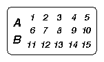
Table D-17. SCSI Device Label for Devices with Restricted Space on the Front Bezel
Key | Description | Placement Procedure |
|---|---|---|
6b | SCSI device label for devices with restricted space on the front bezel; identifies the SCSI protocol (SE or DF) and bus number (0-7); SE SCSI 0 label is part number 024-0637-xxx; DF SCSI 1 label is part number 024-0640–xxx; secondary SCSIBoxes are labeled from label set part numbers 024–0610–xxx through 024–0654–xxx. | Select label based on the slot and bus number of the I/O board. For example, in the default configuration bus 0 on an IO4 board in slot 13 gets the label SE SCSI 130. Place label on flat face of the cable connector, aligning the bottom of the text along the inner long edge of the connector. |
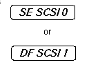
Table D-18. SCSI Device Label for Devices with Minimal Space on the Front Bezel
Key | Description | Placement Procedure |
|---|---|---|
6c | SCSI device label for devices with minimal space on the front bezel; identifies the SCSI channel (A or B); part number 024-0671-xxx. | Place label directly on the face of the drive, ensuring that the label does not block airflow. Indicate whether the device is configured for channel A or B. |

Table D-19. SCSIBox Base Label
Key | Description | Placement Procedure |
|---|---|---|
7a | SCSIBox base label; part number 024-0655-xxx. | Place label on the bottom lip of the inside of the SCSIBox (in front of the drives). For each channel, indicate the channel protocol (SE for single-ended, DF for differential) and the SCSI bus (0 or 1). See Figure D-30. |
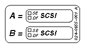
Table D-20. SCSIBox Cover Label
Key | Description | Placement Procedure |
|---|---|---|
7b | SCSIBox cover label; identifies SCSI protocol (SE or DF) and bus number (0-7); SE SCSI 0 label is part number 024-0637-xxx; DF SCSI 1 label is part number 024-0640–xxx; secondary SCSIBoxes are labeled from label set part numbers 024–0610–xxx through 024–0654–xxx. | Select label based on the slot and bus number of the I/O board. For example, in the default configuration bus 0 on an IO4 board in slot 13 gets the label SE SCSI 130. Place label on the inner face of the drive door, in the upper left corner. |
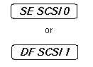
Table D-21. Bulkhead Terminator Connector
Key | Description | Placement Procedure |
|---|---|---|
8 | Bulkhead terminator connector; in early revisions, no distinction between connectors A and B; channel A is the bottom connector, and channel B is the top connector; in later revisions, A and B markings are included on the bulkhead. | None required. |
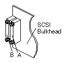
Table D-22. SCSI Terminator Connector Label
Key | Description | Placement Procedure |
|---|---|---|
9 | SCSI terminator connector label; identifies SCSI protocol (SE or DF) and bus number (0-7); SE SCSI 0 label is part number 024-0637-xxx; DF SCSI 1 label is part number 024-0640–xxx; secondary SCSIBox terminators are labeled from label set part numbers 024–0610–xxx through 024–0654–xxx. | Select label based on the slot and bus number of the I/O board. For example, in the default configuration bus 0 on an IO4 board in slot 13 gets the label SE SCSI 130. Place label on flat face of the terminator. |