This chapter describes NetLook, the window on your network that monitors network configuration and traffic flow. It provides a bird's-eye view of the network, which can reveal at a glance a connectivity problem, a security breach, or an effective way to reconfigure a network. Developers of distributed applications can use NetLook to see the pattern of traffic generated by an application.
NetLook's windows allow you to view network traffic and configuration, and to specify the type of network traffic you want to view. It displays complex network information in a simple-to-use and easy-to-understand fashion; you don't need to know packet-level details.
Using lines of varying colors to represent traffic volume between the communicating nodes, NetLook displays both the location and intensity of your network's traffic. A node can be any network device such as a workstation interface or router.
This chapter explains how to:
start NetLook
use the NetLook main window to display network configuration and traffic information
use the NetLook control panels to specify the type of traffic you want to view and configure the display of traffic
use choices on the Actions menu to perform operations on a single node or network segment
use configuration files to retain network and NetLook configuration information for later use
In addition, a variety of NetLook examples are provided. For complete information on NetLook command-line options and resources, see the netlook(1M) manual page in Appendix F, “NetVisualyzer Manual Pages.” Additional information about NetLook configuration files is provided in Appendix D, “Configuration File Formats.”
 | Note: You must have authorization to use NetLook. See “Authorizing NetVisualyzer Users for Snooping” in Chapter 1 and Appendix B, “Authorization Reference,” for details. |
To start NetLook, double-click the netlook icon in the netvis directory view or enter:
netlook |
The first window you see is a NetLook Progress window indicating that NetLook is starting or that your NetVisualyzer license expires within 30 days. You may also see a NetLook Warning window with the message: Could not open ~/network.data: No such file or directory. This message lets you know that NetLook could not find network configuration information saved from a previous NetLook session. Click Continue or press <Enter> to make these windows disappear.
Figure 3-1 shows the appearance of the NetLook main window when NetLook cannot find saved network data and user interface configuration information. In this case, NetLook does not begin snooping and displaying network configuration and traffic information until you use the Snoop control panel to start snooping. Using the Snoop control panel is explained in “Snoop Control Panel” in this chapter.

If NetLook finds one or both of the configuration files ~/network.data (network data) and ~/.netlookrc (user interface), it uses them to draw the network, set up the window configuration, and adjust the settings of the control panels. Figure 3-2 shows how the NetLook main window might appear.

Network data files, typically called network.data, describe the network configuration of network segments and nodes. NetLook uses this configuration to set up the NetLook main window. Each network segment defined in the network.data file is shown in the main window as a separate circle. The name of the network segment given in the network.data file is shown as the name of the network circle. Each interface defined in the network.data file is shown as a node on a network circle. For more information about network data configurations files, see “NetLook Network Data File” in Appendix D.
NetLook looks for ~/network.data and ~/.netlookrc by default; you can override these locations with the –f and –u command-line options or by specifying alternate files in a NetLook resources file; see the netlook(1M) manual page in Appendix F for more information.
If you start NetLook without a network.data file, NetLook must learn the network configuration. A saved network data file, however, tells NetLook about the networks you want to observe so that they are displayed at startup.
If NetLook reads a user interface file that was created while snooping was in progress, snooping starts automatically. See “NetLook User Interface Configuration File” in Appendix D for more information about user interface configuration files.
The NetLook main window shows a detailed view of the network segments known to NetLook. Each network segment is represented by a circle whose size is relative to the number of nodes on the network. Nodes (workstations, routers, bridges, and hubs) appear around the perimeter of each network circle. You can display a node by its name or address (see “NetNode Control Panel” in this chapter).
The ring of network segment circles is updated as new nodes and network segments are discovered. Comparing the network ring to a clock, new nodes are added just before 9 o'clock, and the circle is adjusted so that nodes are equidistant from each other.
Network traffic is displayed in the NetLook main window by color-coded straight lines that appear between nodes. The color at each end of a line indicates the amount of traffic generated at that node that is destined for the node at the other end of the line. You can display traffic between nodes using source and destination routing (lines are shown from source to destination) or physical routing (lines show the “local hops,” the physical path traffic takes through gateways from source to destination). See “Traffic Control Panel” in this chapter for more information.
Network segments active with traffic are displayed in light blue (cyan), and inactive network segments are displayed in dark blue. Network segments that have not experienced any activity while NetLook is running are not known to NetLook and are not displayed unless they are included in a network.data network configuration file that has been read.
Most nodes appear in green. Routers (gateways) are cyan. Display Stations and Data Stations with snooping turned on are magenta. NIS masters are peach, and NIS slaves are white. A user-selected node appears in yellow, regardless of its function. Table 3-1 summarizes these NetLook colors. The colors are listed in order of decreasing precedence, meaning that if a node fits in two or more categories, its color is the color of the first category in the list.
Color | Representation |
|---|---|
Light blue circle | Networks active with traffic |
Dark blue circle | Networks with no traffic |
Yellow characters | Node that has been selected |
Yellow characters | Node that has been adjusted |
Magenta characters | Node running snoop process |
Cyan characters | Gateway |
Peach characters | NIS master |
White characters | NIS slave |
Green characters | Node |
Traffic between nodes is measured in packets or bytes, as configured in the Traffic control panel. The amount of traffic is represented by color-coded lines drawn between communicating nodes. The colors are updated every 5 seconds by default, based on activity during the previous 5 seconds.
The range of possible color values is a range of color map values. Workstations with at least 24 bitplanes use the color range 144 (dark purple) to 151 (light green) by default. Workstations with 8 bitplanes use the color range 8 through 15. You can use showmap(6D) to see what colors these numbers represent (see the section “Show Color Map” in the IRIS Utilities Guide for more information).
Each color step represents a certain number of packets or bytes. You can choose the number of packets or bytes represented by each color. By default, each change (step) in color represents one packet per second in packet mode, or one kilobyte per second in byte mode.
The volume of traffic originating at a node determines the color at the end of a line connecting that node with another. Thus the colors at each end of a line tell you about the volume of traffic in each direction between those two nodes. The colors in the middle of a line are an interpolation of the color map colors in the range from one end point to the other.
For example, suppose the color map range 58 (dark green) to 63 (bright green) on a 24-bitplane workstation is being used and each color represents 10 packets/second. Figure 3-3 shows the relationship between colors and number of packets per second. NetLook is snooping on a network segment with nodes A and B and finds that for a 5-second interval, node A has sent an average of 5 packets per second to node B, and node B has sent 45 packets per second to node A. Since node A generates packets in the range of 0 to 10, color 58 is used at node A, and since node B generates packets in the range 40 to 50, color 62 is used at node B. Since the range from color 58 to color 62 is five colors, the first 20 percent of the line is color 58, the second 20 percent is color 59, and so on. Because of the automatic Gouraud shading done by many Silicon Graphics workstations, the color transitions may appear gradual rather than discreet.

Additional information about configuring traffic lines is available in “Traffic Control Panel” in this chapter.
You can change the portion of the network ring seen in the NetLook main window in both area and scale using the window's scroll bars. Movement is restricted to the ring of network segments known to NetLook.
| Left scroll bar – zoom |
| |
| Bottom scroll bar – shift view left and right |
| |
| Right scroll bar – shift view up and down |
|
In addition, you can use three other methods to change the view area:
Drag the mouse. Press the middle mouse button in the window and drag the hand cursor until the view you desire is displayed; the view will follow the cursor. When you are satisfied with the view, release the middle mouse button.
Drag out a new viewing area. Move the cursor to a corner of the new viewing area you want. Hold the <Alt> key, press the middle mouse button, and move the hand cursor to the opposite corner of the viewing area you want. Release the <Alt> key and the middle mouse button.
Use the Map control panel. Additional methods of adjusting the viewing area and scale using the Map control panel are described in “Map Control Panel” in this chapter.
You can select a node or network segment by single-clicking the left mouse button on a node name for a node or in a network segment circle. The selected node, network, or network segment changes to yellow, regardless of its role in the network. If a dialog box is displayed when you select a choice on the Actions menu (except for “Find...”), the name of the selected node or network is automatically filled in for you.
You can change the order in which nodes appear on a network ring. By default, NetLook arranges nodes in the order in which they are discovered. To rearrange nodes, move the cursor to the node you want to move, press the left mouse button, and drag the node to the position you want it to appear on the ring.

NetLook provides five control panels for use in controlling snooping and configuring the display of nodes and network segments in the main window. Figure 3-4 shows the Controls menu.
To bring up a control panel, select it from the Controls menu. The control panel is automatically placed at the location specified in a .netlookrc file if one is being used, or in a default location otherwise.
The control panels are discussed in the following sections.
Use the Snoop control panel to start or stop monitoring network traffic on a Data Station you specify. Monitoring network traffic on a Data Station (snooping) enables you to display traffic within that Data Station's network segment. To get the maximum amount of information about traffic in your network, turn on snooping on one Data Station in each segment of your network.
Using the Snoop control panel, you can specify a filter if you want to restrict the packets shown by NetLook to a subset of interest to you. An example of the Snoop control panel with snooping turned on for one Data Station is shown in Figure 3-5.

You must have authorization to snoop on a Data Station. See “Authorizing NetVisualyzer Users for Snooping” in Chapter 1 and Appendix B, “Authorization Reference,” for more information.
The sections below describe how to use the Snoop control panel to start and stop snooping and to specify a NetLook filter.
To turn snooping on, enter the name or IP address of the Data Station you want to snoop on in a Data Station entry field if the Data Station isn't in the list, and click the left mouse button on the check box to check it (see Figure 3-5).
If a Data Station you snoop on has multiple interfaces, NetLook assumes that you want to snoop on the interface that matches the name (or IP address) you specified. To specify an interface, use its name as shown in the Address column of netstat -i output. For example, the output of netstat -i is:
Name Mtu Network Address Ipkts Ierrs Opkts Oerrs Coll ipg0 4352 wpd-fddi squaw.wpd.sgi.c 873875 18 485607 1 0 ec0* 1500 b9U-ng gate-squaw.wpd. 0 0 4807 0 0 lo0 32880 loopback localhost 14656 0 14656 0 0 |
You want to snoop on the Ethernet interface, ec0, so use gate-squaw in the Data Station entry field. If you specify squaw, snooping is done on the FDDI interface, ipg0.
You should snoop on only one Data Station per network segment; snooping on other Data Stations on the same network segment will not provide NetLook with any additional information.
As it begins to collect data, NetLook draws traffic patterns and shows network transactions in the NetLook main window. Figure 3-6 shows an example of the NetLook main window after snooping has started. See “The Use of Color in the NetLook Main Window” and “Traffic Control Panel” in this chapter for more information about the colors used for the traffic lines.

To get information on the physical routing of packets (as opposed to endpoint-to-endpoint information), you must snoop on each network segment that packets travel through. (See “Seeing the Physical Path of Traffic Between Two Nodes” in this chapter for more information on observing the physical routing of packets.)
For more information on snooping remotely, see “Monitoring Traffic on Other Network Segments” in this chapter.
To stop snooping on a Data Station, click the “Snoop” check box to the left of the Data Station name or address. The check disappears and snooping on that Data Station is terminated.
To specify a filter to NetLook, enter the filter in the Filter entry field and press <Enter> to make it take effect. You can either type in the filter or use the NetFilters button to invoke NetFilters. When you select a filter in a NetFilters archive, it is automatically copied to the Filter entry field of the Snoop control panel. See Chapter 10, “Creating and Using Filters,” for information on constructing and using filters and Chapter 2, “NetFilters,” for more information about NetFilters.

The Map control panel displays an overview of the network known to NetLook. It shows the entire network ring. (The NetLook main window may show just a portion of the network ring.) A yellow rectangle shows the current position of the view shown on the main window. Figure 3-7 shows the Map control panel for the NetLook main window as it appears in Figure 3-6.
You can change the position of the network currently shown in the main window by manipulating the yellow rectangle in the Map control panel. To do so, move the arrow cursor to another position in the window and press the middle mouse button. The arrow cursor changes to a hand. When you drag the hand cursor, the yellow rectangle follows, and the NetLook main window is updated to reflect the position of the yellow rectangle. Release the mouse button when you are satisfied with the location of the rectangle.
You can also resize the yellow rectangle to change the view and scale of the network shown in the main window. To do this, first press and hold the <Alt> key. Move the arrow cursor to one corner of the new yellow rectangle you want. Press the middle mouse button and drag the hand cursor to the opposite corner. Release the middle mouse button and the <Alt> key. The view in the NetLook main window changes to correspond to new size and location of the yellow rectangle.
The NetNode control panel controls how network segments and nodes are labeled and some aspects of the display of network segments and nodes. Figure 3-8 shows the default NetNode control panel.

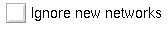
If NetLook receives a packet from a network segment it does not know, it either adds the network segment to the network map or ignores it. If the “Ignore new networks” check box shown in Figure 3-9 is not checked (the default), the new network segment is added; if the check box is checked, all new network segments are ignored. These new network segments are not written to the network data file network.data. To turn off the display of network segments already discovered, see “Hide Control Panel” in this chapter.
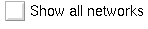
If the “Show all networks” check box shown in Figure 3-10 is checked, all network segments are displayed as though they are active (they appear in light blue). If the check box is not checked, only network segments with active connections appear in light blue. Inactive network segments appear in dark blue. By default, this check box is not checked.

The Label networks radio buttons shown in Figure 3-11 control how network segments are labeled:
| by name | Label networks by the name found in the network database file (for example, /etc/networks, a network.data file, the map that serves the networks, NIS, or DNS). The network database files used are controlled by the –y command-line option and the useyp and hostresorder resources (see “Address/Name Resolution” in Chapter 1 for more information). Label networks by name is the default. If no name can be found, IP network numbers are used. | |
| by IP network number |
|

If the “Ignore new nodes” check box shown in Figure 3-12 is checked, NetLook ignores new nodes not previously known to it. New nodes become known to NetLook when there is traffic to or from them. Checking this check box lets you concentrate on the nodes already discovered. If it is checked, information about new nodes is not written to the network data file Sidenetwork.data.
If the “Ignore new nodes” check box is not checked, new nodes are displayed as they become known to NetLook. By default, this check box is not checked.
If the “Show all nodes” check box shown in Figure 3-13 is checked, all nodes in active networks known to NetLook are displayed, whether or not there is currently traffic to display at that node. If the check box is not checked, only nodes that meet the criteria of the Traffic control panel are shown. By default, this check box is not checked.

The Label nodes radio buttons shown in Figure 3-14 control how nodes are labeled
| by full domain name |
| |
| by local host name |
| |
| by Internet address |
| |
| by DECnet address |
| |
| by vendor code |
| |
| by physical address |
|
When a new node is discovered, its name or address is displayed as requested by the selected radio button. If the requested name or address cannot be found, the labeling specified by the next item in the radio button list is tried, and so on down the list (wrapping to the top of the list if necessary) until a name or address is found. Depending upon whether the –y option was given and the values of the useyp and hostresorder resources, NetLook uses /etc/hosts, NIS, and BIND to search for names and IP addresses. See “Address/Name Resolution” in Chapter 1 for more information.
The Traffic control panel determines how network traffic is displayed in the NetLook main window. Figure 3-15 shows the default Traffic control panel. The remainder of this section describes each section of this control panel.
The For traffic radio buttons shown in Figure 3-16 control whether endpoint routing or physical (gateway) routing of packets is shown:
| show the source and destination |
| |
| show the local hop |
|


The Base scale of traffic radio buttons shown in Figure 3-17 enables you to specify whether NetLook calculates the color of a line based on the number of packets or the number of bytes passing between nodes:
| packets | Scale traffic based on packet count. This is the default. | |
| bytes | Scale traffic based on byte count. |

Figure 3-18 shows the “Each color step represents” and “Traffic volume color map indices” portions of the Traffic control panel.

The colors used for traffic lines are taken from the color map, each color step being one entry in the color map. (See showmap(6D) for information on displaying the color map.) The range of color map entries is specified by the two traffic-volume entry fields. The color map entries in this range are shown in the color bar. They are shown dithered, since the traffic lines in the NetLook main window are dithered.
The dials are used to specify how many packets or bytes (depending upon the scale of traffic) each color map entry represents. The line below the entry fields shows the number of packets or bytes per second that will be indicated by the end color map indices. In the example above, the end indices are 8 and 15, a range of 8 color map entries. Since each color step represents 1 packet per second, color map entry 8 represents 0 packets per second and color map entry 15 represents 7 or more packets per second.
To adjust a dial, click the left mouse button inside the dial circle at the number you want, or press the left mouse button inside the circle and move the cursor so that the marker spins to the number you want.
To change color map indices, replace the current number with the number you want and press <Enter>.
The default color step settings are 1 packet/second or 1024 bytes/second. For 8-bitplane workstations, default color map indices are 8 and 15; for workstations with more than 8 bitplanes, the default indices are 144 and 151.
See “The Use of Color in the NetLook Main Window” in this chapter for more information about traffic line colors.

The “Recalculate color of traffic lines” check box and its entry field are shown in Figure 3-19. If this box is checked, NetLook periodically adjusts the color of the traffic displayed, based on the volume of traffic over the last recalculation interval. By default, this box is checked and the recalculation is done every 5 seconds. To change the value, edit the number and press <Enter>.
If the volume of traffic is greater than the previous volume, the color is rescaled to reflect the new, higher volume. If the volume is smaller than the previously displayed volume, the color is adjusted downward by only one color step. The result is that NetLook always shows high-volume traffic and smoothes intermittent drops in traffic.
You can use scaling to distinguish real-time traffic flow from long-term patterns. When set low (2 or 3 seconds), the traffic display is updated frequently to allow monitoring of real-time traffic. When set high (10 or 15 seconds), traffic patterns accumulate to show traffic on a long-term basis.
If this check box is not checked, the traffic lines are never rescaled down, only up, and the main window shows every connection's highest-ever volume.

The “Delete traffic lines” check box and entry field are shown in Figure 3-20. This line controls the amount of time a traffic line between two nodes remains on the screen after the last packet is seen. If it is checked, traffic lines are removed after the time-out period specified in the entry field. By default, the check box is checked and the time-out period is set to 60 seconds.
To change the value, edit the number and press <Enter>. A short time-out period (for example, 15 seconds) monitors real-time traffic. A longer time-out period (for example, 180 seconds) shows traffic patterns on a long-term basis.
If the check box is not checked, traffic lines remain on the screen indefinitely. This can be used to monitor all connections to the network over a day or a weekend. Unexpected traffic from unexpected sources can be easily detected.
The Hide control panel is used to specify network segments and nodes that you don't want displayed. An example is shown in Figure 3-21. When you want to see these network segments or nodes, you can “unhide” them with this control panel.

In the entry field on the Hide control panel, enter the name or address of the segment or node that you want to hide, and click the Hide button or press <Enter>. The existing traffic lines and nodes are removed from the NetLook main window. The display of nodes and traffic lines resumes, but does not include the network segment or node you specified. The name or address is put in the Hidden objects list in the control panel.
To display a hidden network segment or node, click on its name or address in the Hidden objects list, then click the Unhide button. The network segment or node reappears in the NetLook main window right away, and it disappears from the Hidden objects list.
Hiding an object differs from using “Delete...” on the Actions menu in that NetLook “forgets” an object when you delete it (frees all memory associated with the object), but does not forget it when you hide it. When you hide it, you do not see the object again until you explicitly unhide it. When you delete an object, it is redisplayed only if NetLook discovers it again. When you hide an object, information about that object is written to network.data. When you delete an object and it is not re-discovered, that object is omitted from any network.data file that you save.
The Actions menu provides you with a variety of choices that are described below. Figure 3-33 shows the basic Actions menu. If Spectrum® software is installed on your Display Station, an additional “Spectrum” choice appears.

Many of the choices on the Actions menu bring up a Prompt dialog box and ask you to supply the name or address of a network segment or node. To use a shortcut, select the network segment or node that you are going to supply to the dialog box before selecting from the Actions menu. The name or address of that network segment or node automatically appears in the entry field of the Prompt dialog box that appears.
When you choose “Information” from the Actions menu and no objects are currently selected, a window appears that displays the number of network segments and nodes that are currently known to NetLook. An example of this NetLook Information window is shown in Figure 3-23.

If a node is selected when you choose “Information,” a window like the one shown in Figure 3-24 appears.

If a network segment is selected when you choose “Information,” a window like the one shown in Figure 3-25 appears.

If a traffic line is selected when you choose “Information,” a window like the one shown in Figure 3-26 appears. When NetLook is displaying a small portion of the network and a traffic line goes off the screen, you can easily trace the connection by selecting the line and choosing “Information” from the Actions menu.

Like most NetLook menu choices, “Information” has a keyboard accelerator, <Alt-i>, that can be used instead of selecting “Information” from the Actions menu.
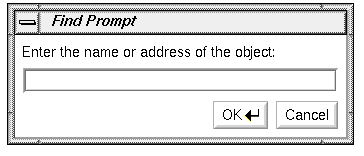
The “Find...” action places a particular node or network segment in the center of the NetLook main window. It is a convenient way to locate a particular node or network segment when the network ring in the main window is large and complex.
Click “Find...” on the Actions menu or use the keyboard accelerator <Alt-f> and the window shown in Figure 3-27 appears. Type the name or address of the node or network segment you wish to find. Press <Enter> or click the OK button. The node or network segment is placed in the center of the viewing window and displayed in yellow, regardless of its role in the network.
The “Ping...” action sends a request for a response to a node. This interface to the ping(1M) command is an easy way to generate traffic that you can observe in the NetLook main window.
You can see the network traffic generated by “Ping...” in the NetLook main window only if ICMP protocol traffic is displayed. This is the default; make sure that any filter you have specified allows icmp traffic to be displayed. Also, in the Traffic control panel, if you choose the “show the source and destination” radio button, it is easier to recognize the traffic you have generated in the NetLook main window.
Select “Ping...” on the Actions menu or use the keyboard accelerator <Alt-p> and the window shown in Figure 3-28 appears. Type the name or address of the node you wish to ping into the entry field, and press <Enter> or click the OK button. The default ping command is ping -R. The command that is run is set with a resource that you can change.
A window appears and shows the response of the node (ping output). Figure 3-29 shows an example.

The ping process continues until you stop it by moving the cursor into the Ping window and pressing <Ctrl-c>. To close the Ping window, choose “Quit” on the window's window menu or double-click the Window menu button in the upper left corner of the Ping output window.
For more information, see the ping(1M) manual page.
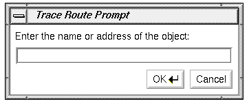
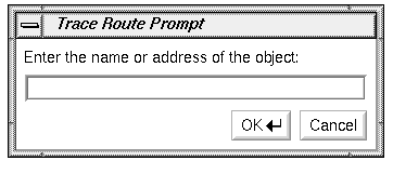
The “Trace Route...” action traces the route taken by a packet. It displays a list of the gateways that a packet travels through to get to a node that you specify. “Trace Route...” is an interface for traceroute(1M). To use “Trace Route...”, the subsystem eoe2.sw.ipgate must be installed, and you must have started NetLook as superuser (root).
When you select “Trace Route...” on the Actions menu or use the keyboard accelerator <Alt-t>, the window shown in Figure 3-30 appears; type the name or address of the node to which you want to send a packet, and press <Enter> or click the OK button. traceroute is the default command, but it can be changed using a resource.
A Trace Route output window appears and shows the response of the node (traceroute output). An example is shown in Figure 3-31.

To close the Trace Route window, choose “Quit” on the window menu or double-click the Window menu button in the upper left corner of the Trace Route window.
For more information, see the traceroute(1M) manual page in Appendix F.
When you choose “Home” from the Actions menu or press the <Home> key, the NetLook main window is redrawn to show the entire network.
“Delete...” on the Actions menu enables you to delete a network segment or node from the NetLook main window. Thus you can display only the network segments and nodes you want to study. If NetLook rediscovers a network segment or node that you have deleted (because it detects traffic to or from that object), the network segment or node reappears.
When you choose “Delete...” from the Actions menu or use the keyboard accelerator <Alt-d>, the window shown in Figure 3-32 appears.

Enter the name or address of the network segment or node you want to delete. If you select the object before choosing “Delete...”, the name or address is automatically placed in the entry field. Press <Enter> or click the OK button to delete the network segment or node.
If you save the configuration when you quit NetLook, network segments and nodes you have deleted will not appear in the main window the next time you start NetLook, because the deleted network segments and nodes were not saved.
If you have a large network and want to delete many nodes, it may be faster to edit the network.data file (see “Monitoring Selected Nodes” in this chapter for details).
“Delete...” differs from the Hide control panel in that NetLook forgets all information about a deleted network segment or node, but does not forget about a hidden network segment or node. Memory is freed when a network segment or node is forgotten, which can be useful if you have a large network.
“Ignore new networks” and “Ignore new nodes” in the NetNode control panel are similar to “Delete...”. Use those check boxes to automatically delete network segments and nodes that are discovered in the future.
“Delete All” or the keyboard accelerator <Alt-a> clears all network segments and nodes from the display except your network segment and terminates all snooping. All network segments and nodes that were known to NetLook are forgotten, just as if you had used the “Delete...” action for each one. To restart snooping, use the Snoop control panel as described in “Snoop Control Panel” in this chapter. Once you restart snooping, network segments and nodes appear as they are discovered.
“Delete All” provides a convenient way to rid your display of network segments and nodes that no longer exist and to restart NetLook with a “clean slate.”
When you select “Spectrum” from the Actions menu, NetLook sends the selected network segment or node (if any) to Spectrum. If the Spectrum user interface, SpectroGRAPH, is running, it opens a window with the Spectrum view of that network segment or node. If SpectroGRAPH is not running or the selected object is unknown to Spectrum, nothing happens.
The menu choice “Spectrum” appears on the Actions menu only if Spectrum software is installed.

The choices on the File menu enable you to open NetLook network configuration files, save the current network data and user interface configuration to files, and quit. Figure 3-33 shows the File menu.
“Open...” opens a previously saved network data file.
Click “Open...” on the File menu and a file prompter window appears. Use the procedure in the section “Using a File Prompter” in the Introduction to specify the file name from which you want to read network configuration data. The file is then read, and all snooping stops. To restart snooping according to the new configuration, use the Snoop control panel as described in “Snoop Control Panel” in this chapter.
See “NetLook Network Data File” in Appendix D for more information about network data files.
The “Save Networks” choice enables you to save network configuration information. This choice has a rollover menu with two choices, “Save” and “Save As...”. These choices save network configuration information to the file ~/network.data or to a file name of your choice, respectively. When you choose “Save As...”, a file prompter window appears. Use the procedure in the section “Using a File Prompter” in the Introduction to specify the file name for the network configuration data.
By default, the file ~/network.data is read when you start NetLook; you can specify a different network data file at startup with the –f option or read a network data file at any time using “Open...” on the File menu.
See “NetLook Network Data File” in Appendix D for more information.
“Save Controls” enables you to save NetLook user interface configuration information. This choice has a rollover menu with two alternatives, “Save” and “Save As...” to save user interface configuration information to the file ~/.netlookrc or to a file name of your choice, respectively. When you choose “Save As...”, a file prompter window appears. Use the procedure in the section “Using a File Prompter” in the Introduction to specify the file name for the user interface configuration data.
By default, the file ~/.netlookrc is read when you start NetLook; you can specify a different user interface configuration file at startup with the –u command-line option or the NetLook*controlsFile resource.
See “NetLook User Interface Configuration File” in Appendix D for more information.
To exit NetLook, select “Quit” from the File menu. A NetLook Question window appears. To save the current network and user interface configuration in the files shown in the message and to quit NetLook, click the Yes button. To quit without saving configuration information, click the No button. If you want to write the information to other files or decide not to quit NetLook, click the Cancel button.
This section provides a variety of examples and tips for using NetLook. The remaining sections in this chapter describe examples of using NetLook, editing the network.data file to provide additional information to NetLook, and customizing the display of network segments and nodes.
In some situations such as a multivendor, multiprotocol network, you may want to monitor only certain traffic types. To do this, use NetLook's protocol filters to isolate traffic by protocol.
For example, to optimize NFS client/server configuration in a multiprotocol network, examine only its NFS traffic. Just specify a filter of
nfs
and press <Enter> in the filter entry field of the Snoop control panel. This filtering process reduces the amount of information displayed for analysis and makes NFS traffic patterns easier to understand.
Because each network is unique, you may want to try different settings on the Traffic control panel to see which ones work best for you. To see greater differentiation in traffic, for example, recalculate the color of traffic lines every 5 seconds and color step to 1 packet/second or 1024 bytes/second. For less differentiation in traffic, set the number of packets or bytes that a color step represents to a higher number.
Assume that a Display Station is connected to net1. As NetLook captures and displays network packets, traffic lines accumulate as shown in Figure 3-34.

The display shows only traffic packets that have passed through net1, where the Display Station is attached. In fact, net1 is the only network segment with any internal traffic displayed. This, however, does not indicate that no internal traffic occurs in other network segments or that no traffic occurs between other network segments. In reality, it is likely that just as much traffic occurs within net2 and net3 while the Display Station is busily collecting traffic data in net1. NetLook cannot show the traffic within net2 and net3 because it is not snooping on those network segments. It can only capture and display packets internal to those network segments on which it is snooping.
To use NetLook to monitor additional network traffic from the central Display Station, install Data Station software on one workstation in every network segment. Then, from the Display Station, you can activate the remote data-collection mechanism by using the Snoop control panel to start snooping on each of these Data Stations. Doing so causes each Data Station to collect local traffic data in exactly the same way that the central Display Station collects traffic information in its own network segment. Each Data Station forwards the data to the central Display Station for simultaneous graphical display. The resulting NetLook main window will look like Figure 3-35.

NetLook's display of overall traffic distribution tells a great deal about whether the network's configuration is optimal. For example, when sources and destinations are shown (rather than local hops), if two nodes on two separate network segments consistently show an intense connection, move them to the same network segment. Leaving them on two different network segments exerts unnecessary load on the interconnecting router.
Also, if one network segment shows much more internal traffic than the others, you may be able to improve the network's overall response by moving some of that network segment's nodes to the other network segments and balancing the overall distribution of traffic loads.
At times, NetLook's display of the network configuration may not be complete, even though it may appear to have stabilized. You may, for example, know that a particular node named elm is on another network segment and that elm is listed in /etc/hosts; however, NetLook doesn't show it. Possible explanations include:
elm is connected to the network but has not been communicating with other nodes while NetLook has been snooping.
elm is no longer connected to the network. It may be powered down or disconnected from the network. To determine if elm is responding to the network, use “Ping...” on the Actions menu to ping node elm. Pinging a node causes 64-byte packets to be continuously sent to that node until stopped with <Ctrl-c>. An unsuccessful ping with 100% packet loss means that elm is not receiving any of the packets and that it is no longer connected to the network.
elm has been communicating with other nodes, but its traffic packets have never been routed to or through a network segment on which NetLook is snooping. NetLook captures packets only on network segments on which it is snooping. If elm communicates only with nodes in network segments on which there is no snooping, NetLook will not be able to capture and display the packets.
elm's protocol is not monitored. You may be using a filter that excludes the protocol that traffic to and from elm is using.
With the NetNode control panel, you choose either “show the source and destination” (display source and destination routing) or “show the local hop” (display physical routing). This example explains the difference between these two different ways to display traffic and describes how to see the physical routing of packets that travel through gateways.

Assume that you are snooping on two network segments, as shown in Figure 3-36, and your Display Station is in net1. The current traffic display setting is “show the source and destination.” node1 in net1 copies a file to node2 in net2 using rcp(1). As shown in Figure 3-36, NetLook displays a connection between node1 and node2 to indicate that the two nodes are communicating with each other.
In source and destination routing display, the connection appears as a straight line regardless of how packets are physically routed. NetLook displays the logical connection based on a packet's source (node1) and destination (node2).
To see the physical path that the remote copy traffic takes, do these things:
Change the network.data file as described in “Showing Gateway Nodes” in this chapter so that NetLook can recognize that two or more interfaces are on single node. Do this for all nodes that could possibly serve as gateways between net1 and net2.Verify that you are snooping on all network segments along all possible paths of traffic from node1 to node2.
Enter a filter that filters out all traffic except the traffic you want to see. For example, the filter ip.between node1 node2 shows only traffic between node1 and node2.
On the Traffic control panel, select “show the local hop.”

The remote copy between node1 and node2 now appears as shown in Figure 3-37. This display shows that the node router and its interfaces router1_2 and router2_1 are used as the physical path for packets between node1 and node2.

Selecting “show the local hop” without editing the network.data file to specify which nodes are gateways is also useful. In this case, no end-to-end traffic is shown between nodes on different network segments. For example, Figure 3-38 shows the display for the rcp example above. You can see all of the traffic internal to each network segment.
Suppose you plan to leave for the weekend and want to monitor and record all nodes trying to access the node named secret during the weekend. Set up NetLook this way before you leave:
Capture only traffic going to or from secret by specifying a filter in the Snoop control panel. If secret's address and name are mapped in /etc/ethers (or NIS or BIND), use this form:
host secret
Or, you can use secret's physical address instead:
host 8:0:69:2:f:c1
Make sure that the “Delete traffic lines” check box in the Traffic control panel is not checked so that all collected data will appear on the screen indefinitely.
Click “Delete All” on the Actions menu to clear the NetLook main window.
Using the Snoop control panel, start snooping on a workstation on the same network segment as secret.
After the weekend, check the NetLook screen. No traffic lines indicate that no security breach occurred; no traffic packets have either entered or left secret. If there are traffic lines, a breach has occurred. The names of all nodes that communicated with secret during the weekend appear on the screen.
A router or gateway is a node that has two or more interfaces, each to a different network. Routers forward packets between the networks to which they are connected. NetLook recognizes each of the interfaces, but does not know that they are on the same node; however, with your help, NetLook can display gateway or router traffic between the two interfaces.
To see this configuration represented in NetLook, you must edit the network.data file and create the association between the interfaces of the gateway.
For example, suppose two networks, engineering-1 and engineering-2, have the gateway named redoubt between them. The network.data file saved from NetLook looks like this:
NetLook 1.10
Network engineering-1 {
        IPNet   192.26.75
        Segment engineering-1 {
                IPNet  192.26.75
                Node  {
                        Interface redoubt {
                                PhysAddr        8:0:69:2:4:45
                                IPAddr          192.26.75.1
                        }
                }
        }
}
Network engineering-2 {
        IPNet                192.26.61
        Segment engineering-2 {
                IPNet                192.26.61
                Node  {
                        Interface gate-redoubt {
                                PhysAddr        2:cf:1f:b0:0:16
                                IPAddr          192.26.61.1
                        }
                }
        }
}
|
The node redoubt has two node objects, and each node object describes one of redoubt's interfaces. Create the association between the interfaces by editing the network.data file and changing the node objects for redoubt. Add the name redoubt to each node object definition, which makes both node statements describe the same node object.
The edited file looks like this:
NetLook 1.10
Network engineering-1 {
        IPNet   192.26.75
        Segment engineering-1 {
                IPNet   192.26.75
                Node redoubt {
                        Interface redoubt {
                                PhysAddr        8:0:69:2:4:45
                                IPAddr          192.26.75.1
                        }
                }
        }
}
Network engineering-2 {
        IPNet   192.26.61
        Segment engineering-2 {
                IPNet   192.26.61
                Node redoubt {
                        Interface gate-redoubt {
                                PhysAddr        2:cf:1f:b0:0:16
                                IPAddr          192.26.61.1
                        }
                }
        }
}
|
When you restart NetLook using physical (“local hop”) routing display and this network.data file, you will see a line that connects the two interfaces as traffic flows from one interface on redoubt to the other.
NetLook cannot determine if a network segment is made up of a single segment or multiple segments that are connected with a repeater or bridge. For example, suppose you have a network with two bridged segments and you want each segment to appear as a separate circle in the NetLook main window.
The original network.data file looks like this:
NetLook 1.10
Network engineering-1 {
        IPNet   192.26.75
        Segment engineering-1 {
                IPNet 192.26.75
                Node  {
                        Interface cheese {
                                PhysAddr        aa:0:4:0:e8:4
                                IPAddr          192.26.75.14
                                DNAddr          1.232
                        }
                }
                Node  {
                        Interface squaw {
                                PhysAddr        8:0:69:2:0:f9
                                IPAddr          192.26.75.11
                        }
                }
                Node  {
                        Interface kaibab {
                                PhysAddr        8:0:69:2:1:51
                                IPAddr          192.26.75.29
                        }
                }
                Node  {
                        Interface illyria {
                                PhysAddr        8:0:69:2:f:8c
                                IPAddr          192.26.75.12
                        }
                }
        }
}
|
Assume two nodes are on each segment, cheese and kaibab on a segment named segment-1, and squaw and illyria on a segment named segment-2. You must edit the network.data file to divide the network into its segments. First add another segment in the network engineering-1 and then separate the nodes appropriately. Also add names for each of the segments.
After editing, the file looks like this:
NetLook 1.10
Network engineering-1 {
        IPNet   192.26.75
        Segment segment-1 {
                Node  {
                        Interface cheese {
                                PhysAddr        aa:0:4:0:e8:4
                                IPAddr          192.26.75.14
                                DNAddr          1.232
                        }
                }
                Node  {
                        Interface kaibab {
                                PhysAddr         8:0:69:2:1:51
                                IPAddr           192.26.75.29
                        }
                }
        }
        Segment segment-2 {
                Node  {
                        Interface squaw {
                                PhysAddr         8:0:69:2:0:f9
                                IPAddr           192.26.75.11
                        }
                }
                Node  {
                        Interface illyria {
                                PhysAddr         8:0:69:2:f:8c
                                IPAddr           192.26.75.12
                        }
                }
        }
}
|
The names segment-1 and segment-2 are added to the segment definitions. Nodes cheese and kaibab are listed under segment-1 and nodes squaw and illyria are listed under segment-2. When you start NetLook using this file, two circles appear, each representing a segment. If the segments are connected by a “smart” bridge, however, you must have a Data Station on each segment and define the Data Station in the file in order to show traffic on each segment.
To monitor just a few nodes, comment out or remove the node description for those nodes that you do not want to appear on the network. To comment out a node, begin each line of the node description with a pound (#) character. Make sure each remaining node definition contains two opening and two closing braces, as shown in the previous examples. (See “Delete” and “Hide Control Panel” in this chapter for alternate ways to remove nodes from the network.)
Restart NetLook using the edited file (use the –f command-line option or use “Open” on the File menu). You must also stop nodes not previously known to NetLook from being added to the network. To do this, open the NetNode control panel and check the “Ignore new nodes” check box.