This chapter explains replacing field-replaceable units:
opening and closing the fan module
replacing or adding a power-supply module
replacing a fan module
replacing or adding a battery backup unit
replacing the power distribution unit in a Challenge RAID rack
installing an additional chassis assembly in a Challenge RAID rack
Before you follow procedures explained in this chapter, note the following points:
 | Caution: To prevent thermal shutdown of the storage system, never operate it for more than two minutes with the fan module open. |
Do not operate the system with an open SP slot.
SCSI terminators must be in place at all times during operation. Removing them causes the storage system to crash.
 | Note: For instructions on installing an add-on disk module array, upgrading an SP, replacing or adding an SP module, and installing an additional chassis assembly in a Challenge RAID rack, see Chapter 6, "Maintaining and Upgrading SPs." |
Figure 7-1 shows the location of FRUs. Only SSEs replace these.
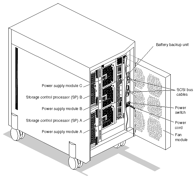
Figure 7-2 shows the Challenge RAID field-replaceable units (FRUs) in one RAID chassis assembly of a Challenge RAID rack storage system. Only SSEs replace these.
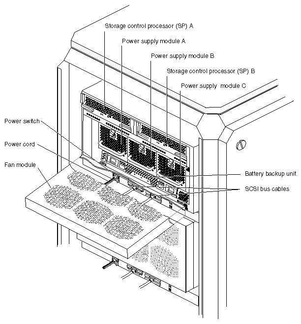
To remove or install an SP, power supply, or battery backup unit, you must unlock and swing open the fan module:
On the back of the storage system, move the fan module's latch to the UNLOCK position, as shown in Figure 7-3.
Swing open the fan module, as shown in Figure 7-4.
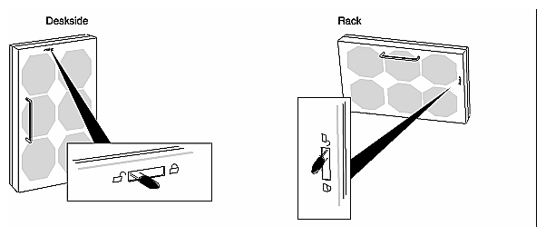
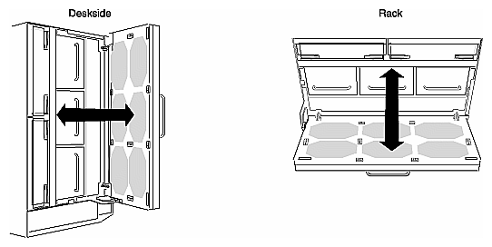
Close the fan module by reversing these steps.
| Caution: To prevent thermal shutdown of the storage system, never operate the storage system for more than two minutes with the fan module in the open position. |
You can replace a failed power supply module (voltage semi-regulated converter, or VSC) or add a new one while the storage system is powered on. However you must complete steps 2 through 6 within two minutes to avoid automatic thermal shutdown of the storage system. Before you begin to replace or add a power supply module, make sure that you understand all the steps in these procedures.
This section explains
replacing a power supply module
adding a power supply module
To replace or add a power supply module, follow these steps:
Unpack the power supply module and place it within reach of the storage system.
Unlock and open the fan module, as shown in Figure 7-3 and Figure 7-4.
If you are adding a power supply module, remove the power supply module filler module by pushing down on its latch and pulling it out of the slot by its latch, as shown in Figure 7-5.
As indicated in Figure 7-5, a power supply module filler module looks similar to a power supply module without its handle.
Caution: If you are replacing a power supply in a system with more than one installed, be sure to remove the one(s) with the replace light activated. Removing an active power supply introduces an additional fault condition that causes the Challenge RAID to shut down. Caution: To maintain proper cooling, never operate the storage system with an empty power supply module slot. Reserve the filler module. Install the replacement or add–on power supply module, as shown in Figure 7-6.
Immediately close and lock the fan module, as shown in Figure 7-3.
If the storage system is not running, power it on, as explained in Section 3.9, "Powering On Challenge RAID," at the end of Chapter 3.
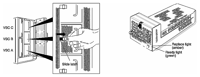
To add a power supply module, follow these steps:
Unpack the power supply module and place it within reach of the storage system.
Unlock and open the fan module, as shown in Figure 7-3 and Figure 7-4.
Remove the power supply module filler module by pushing down on its latch and pulling it out of the slot by its latch, as shown in Figure 7-5.
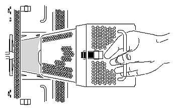
Grasp the power supply module by its handle and push it into the slot until it latches into place, as shown in Figure 7-6.
You can replace a failed fan module while the storage system is powered on. However, you must complete Steps 2 through 7 within two minutes to avoid thermal shutdown of the storage system. Before you remove the fan module, make sure that you understand all the steps in this procedure.
| Note: To avoid thermal shutdown of the storage system, never operate it for more than two minutes with the fan module removed or in the open position. |
To replace the fan module, follow these steps:
Unpack the replacement fan module and place it within reach of the storage system.
Unlock and open the failed fan module, as shown in Figure 7-3 and Figure 7-4.
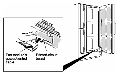
Disconnect the fan module's power, as shown in Figure 7-7.
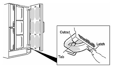
Press the fan module's latch and guide the tab through the cutout, as shown in Figure 7-8.
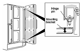
Lift the fan module free of the hinge pins and release the latch, as shown in Figure 7-9.
To install the replacement fan module, lift it onto the hinge pins and latch it, as shown in Figure 7-9.
Press the replacement fan module's latch and guide the tab through the cutout, as shown in Figure 7-8.
Connect the fan module's power, as shown in Figure 7-7.
All six fans begin to rotate.
Immediately close and lock the fan module as shown in Figure 7-3 and Figure 7-4.
You can replace a failed battery backup unit or install one (the battery backup unit is optional) while the storage system is powered on. However, you must complete steps 2 through 6 within two minutes to avoid thermal shutdown of the storage system. Before you remove or add the battery backup unit, make sure that you understand all the steps in the following procedure.
Unpack the battery backup unit and place it within reach of the storage system.
Unlock and open the fan module, as shown in Figure 7-3 and Figure 7-4.
If you are replacing a battery backup unit, remove the failed battery backup unit, slide both latches in the direction shown in Figure 7-10, and pull the battery backup unit or filler panel from the chassis.
If you are adding a battery backup unit, remove the filler module as shown in Figure 7-10.
Push the battery backup unit or filler panel into the slot until it latches into place, as shown in Figure 7-11.
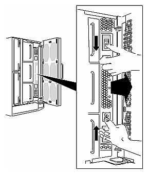
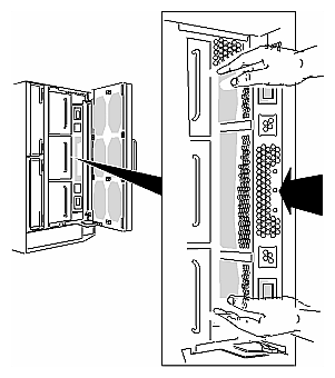
| Caution: To maintain proper cooling, never operate the storage system without a battery backup unit or filler panel installed. Save the filler panel to fill the slot in case you need to operate the storage system with the battery backup unit removed temporarily. |
Immediately close and lock the fan module, as shown in Figure 7-3 and Figure 7-4.
This section explains how to swap out a failed power distribution unit from the Challenge RAID rack. This unit is attached to the base of the rack.
Work with the system administrator at the site to power down the rack. Unplug the power cable.
Remove the side panels from the Challenge RAID rack and open the rear door. It should not be necessary to remove the rear door.
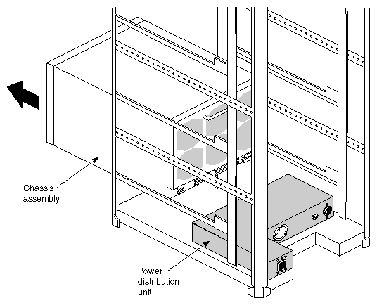
Note: Rehanging the rear door might require a second person because of the difficulty of lining up the three pinlocks. Remove the six screws that hold the lowest chassis assembly in place and push the chassis assembly halfway out of the rack to clear access to the power distribution unit. See Figure 7-12.
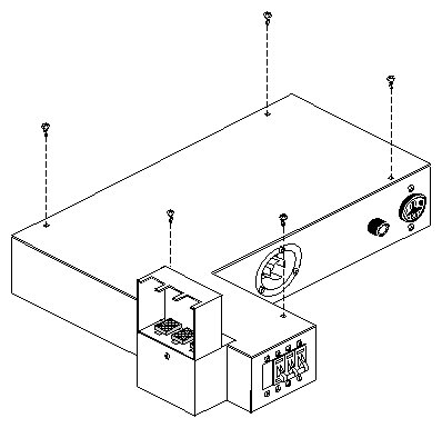
Remove the five screws that attach the lid of the failed power distribution unit and remove the lid, as shown in Figure 7-13.
Inside the unit, remove the four screws that attach it to the rack frame, as shown in Figure 7-14.
Attach the replacement power distribution unit and its cover.
Reseat the chassis assembly and replace the screws. Replace the side panels. Reattach the power cable. Work with the system administrator at the site to power on the system.
 | Warning: Two persons are required to install additional chassis assemblies in a Challenge RAID rack. Do not undertake this procedure unless another qualified Silicon Graphics SSE is available for it. |
To install an additional chassis assembly in a Challenge RAID rack, follow these steps:
Unpack the unit and verify that all parts are present. If they are not, notify the shipper of the missing parts.
To reduce the weight of the chassis assembly for insertion into the rack, remove FRUS from the new chassis assembly:
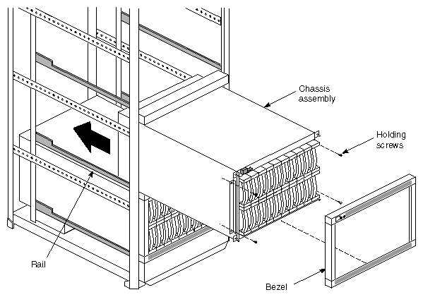
disk modules and front bezel (see Figure 7-15)
SPs, VSCs, BBUs
fan assemblies
Remove the filler panel at the next open chassis assembly location, starting at the bottom of the rack. (You fill the rack with chassis assemblies starting at the bottom, not at the top.)
With another SSE, lift the empty chassis assembly you want to install.
Lifting the empty chassis assembly, engage the rails at the rear of the open chassis location.
Slide the chassis assembly into the rack as shown in Figure 7-15.
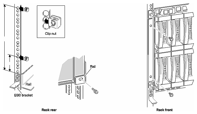
Secure the chassis assembly with six screws, as shown in Figure 7-16.
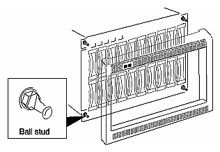
Position the front bezel and push it onto the ball studs, as shown in Figure 7-17.
Install the FRUs that were removed.
Connect the power cables. Power the unit on and check for error conditions.
Repeat steps 3 through 10 for additional chassis assemblies to be installed.
Shut down the CHALLENGE RAID rack and the host; connect the SCSI cables between the host and the newly installed chassis assembly or assemblies.
Bring up the storage system and the host; configure the disks and perform other software tasks as explained in Chapter 4.