This chapter explains
opening and closing the fan module
locating the SPs
replacing or adding an SP
installing or removing SP memory modules (SIMMs)
upgrading FLARE 7.xx to FLARE 8.xx for Sauna
upgrading to FLARE 9.xx in a storage system with RAID-3 LUNs
Before you follow procedures explained in this chapter, note the following points:
 | Caution: To prevent thermal shutdown of the storage system, never operate it for more than two minutes with the fan module open. |
Do not operate the system with an open SP slot.
SCSI terminators must be in place at all times during operation. Removing them causes the storage system to crash.
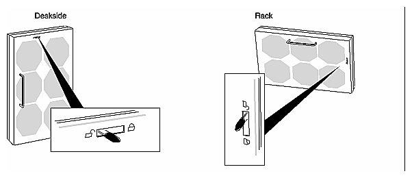
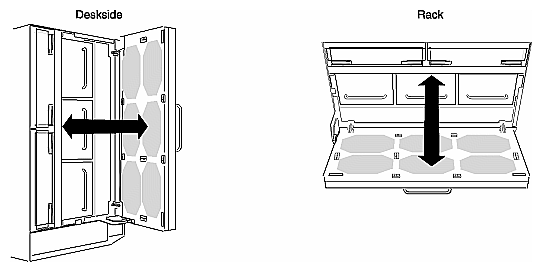
To remove or install an SP, power supply, or battery backup unit, you must unlock and swing open the fan module:
On the back of the storage system, move the fan module's latch to the UNLOCK position, as shown in Figure 6-1.
Swing open the fan module, as shown in Figure 6-2.
Close the fan module by reversing these steps.
| Caution: To prevent thermal shutdown of the storage system, never operate the storage system for more than two minutes with the fan module in the open position. |
Figure 6-3 shows the location of SPs in the deskside system.
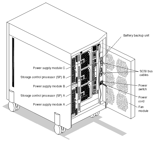
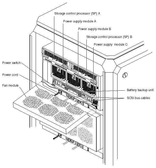
Figure 6-4 shows the SPs in a RAID chassis assembly of a Challenge RAID rack storage system.
If the storage system has one SP, you cannot replace a failed SP without powering down the storage system You must reboot the operating system software once you install the replacement SP.
 | Note: If an SP fails, caching is disabled until the failed SP is replaced. |
If the storage system has two SPs, you can replace a failed SP without powering down the storage system.
If necessary, use the auto-assign capability to transfer control of the physical disk units from the failed SP to the working SP, as described in Section 6.3.1, "Using the Auto-Assign Capability in the Case of a Failed SP." If the storage-system cache is enabled, disable it as described in Section 4.12.1, "Setting Cache Parameters," in Chapter 4.
If you are installing a second SP in a system that has only one, you must remove the storage-control SP filler board in the slot for the second SP board.
This section explains
using the auto-assign capability in the case of a failed SP
removing an SP
installing an SP
If one of two SPs becomes physically unavailable to the system, that is, if an SP fails or becomes disconnected, the Challenge RAID storage system can automatically reassign the LUNs it controls to the remaining SP.
Auto-assign controls the ownership of the LUN when an SP fails in a storage system with two SPs. With auto-assign enabled, if the SP that owns a LUN fails and the server tries to access that LUN through the second SP, the second SP assumes ownership of the LUN so the access can occur. The second SP continues to own the LUN until the SP's power is cycled (turned off and on again). When the power is cycled, ownership of each LUN returns to its default SP. If auto-assign is disabled in the previous situation, the other SP does not assume ownership of the LUN, so the access to the LUN does not occur.
| Note: Consult with the customer before changing LUN ownership. Many systems (such as IRIS FailSafe systems) have failover software, which make using the auto-assign capability unnecessary. |
The process consists of
using RAIDGUI to enable auto-assign
powering off the failed SP
In the command-line interface, auto-assign is disabled by default; in RAIDGUI, it is enabled by default. Normally, disabling auto-assign is recommended for most systems, particularly those with failover software.
To enable auto-assign to reassign LUNs, follow these steps:
To start RAIDGUI, enter the following on the host to which the Challenge RAID storage system is cabled:
/usr/raid5/raid5gui
After introductory screens, the Select Hosts window appears, Select a host, or enter one by clicking Add and entering the name or IP address of the host you want to add.
Note: For more information, see Chapters 3 and 4 of the CHALLENGE RAID Owner's Guide, revision 007-2532-007. Click Select at the bottom of the window. If RAIDGUI was able to communicate with the agent on the server, the Select Chassis window appears. Select the name of the chassis connection that you want to manage and click Select.
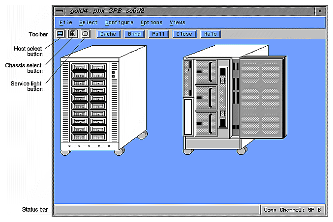
The Select Chassis and Select Hosts windows close, and the Equipment View for the storage system appears. This window depicts the storage system; Figure 6-5 shows an example.
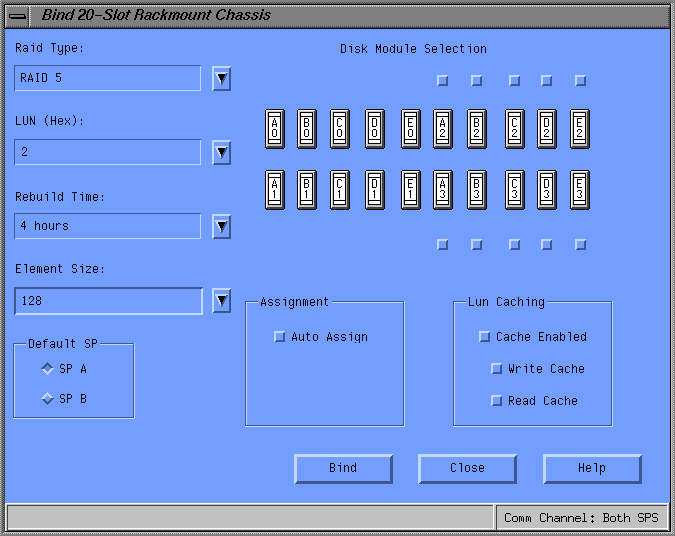
Click the Bind button. Figure 6-6 shows an example.
Select the SP that is to take over LUN ownership (the surviving SP).
If the Auto Assign select button in the Assignment field is not checked, select it to enable auto-assign.
Exit RAIDGUI.
Note the following points:
Auto-assign capability cannot be used in the case of problems caused by a defective Challenge to Challenge RAID connection, such as a damaged cable.
To force auto-assign, power off the failed SP. You do not need to power off the Challenge RAID storage system. To power off a Sauna SP, use its switch; to power off a Phoenix SP, remove it entirely from the chassis.
Powering off an SP requires opening the fan module at the back of the storage system. Because the fan module must not be left in the open position for more than two minutes, make sure you can complete this process within that time limit.
| Caution: To prevent thermal shutdown of the storage system, never operate the storage system for more than two minutes with the fan module in the open position. |
Follow these steps:
Make sure a static-free work surface is available near the Challenge RAID storage system for the SP, if it is Power-PC based.
On the back of the Challenge RAID storage system, move the fan module's latch to the UNLOCK position, as shown in Figure 6-1. Swing open the fan module, as shown in Figure 6-2.
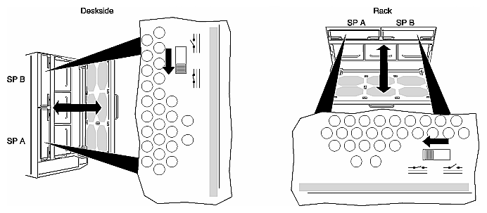
For a failed Sauna SP, disable it by sliding the switch to the Disable position, as shown in Figure 6-7.
The Phoenix SP does not have power switches; disable it by removing it from the chassis, as explained in Section 6.3.2, "Removing an SP."
Immediately close and lock the fan module.
In a system with two SPs, you can replace one while the storage system is powered on. However, to avoid automatic thermal shutdown of the storage system, you must complete Steps 1 and 2 within two minutes and Steps 4 through 8 within two minutes.
If you are installing a second SP in a system that has only one, follow the procedure in this section to remove the SP filler board in the slot for the second SP board.
Before you begin to remove an SP or filler board, make sure that you understand all the steps in the following procedure.
| Note: If you must replace a failed SP and you do not have a replacement for it, leave the failed SP installed until the replacement is available. Do not operate the system with an open SP slot. |
To remove an SP or filler board, follow these steps:
Unlock and open the fan module, as shown in Figure 6-1 and Figure 6-2.

Warning: Some components on the SP become hot during operation. To prevent personal injury, disable the SP's power and do not attempt to remove the SP until you have waited at least five minutes for these components to cool. If the SP that you want to remove is a Sauna, disable its power by sliding the switch to the Disable position, as shown in Figure 6-7. Immediately close and lock the fan module to let the SP cool.
If the SP is a Phoenix, removing it from the chassis disables its power.
Read "Avoiding Electrostatic Discharge (ESD) Damage" in Chapter 5. Put the ESD wrist band (strap) around your wrist with the metal button against your skin.
After waiting five minutes, reopen the fan module, and attach the wrist band's clip to the ESD bracket on the bottom of the storage system, as shown in Figure 5-3 and Figure 5-4 in Chapter 5.
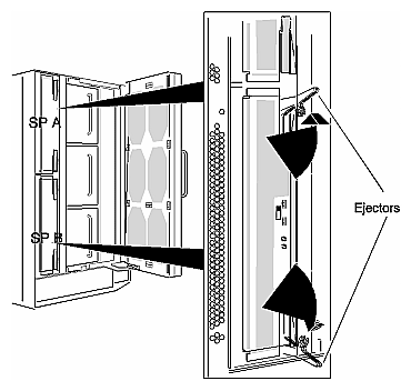
Pull both ejectors until they unlock and the SP or filler board starts coming out of chassis, as shown in Figure 6-8.
Rest the edge of the SP or filler board on the palm of your hand. With your other hand, pull it out of the chassis, making sure not to any touch any electronic components or circuits.
Place the SP component–side up on a static–free work surface.
| Note: Before shipping a failed SP, remove its memory modules as described in Section 6.4.2, "Removing SP Memory Modules." Write down the part numbers that are on the two part number labels on the SP board. |
You can install an SP while the storage system is powered on. However, you must complete steps 5 through 9 within two minutes to avoid automatic thermal shutdown of the storage system. Before you begin to install an SP, make sure that you understand all the steps in the following procedure.
| Caution: For caching, both SPs must have the same amount of cache memory in order for caching to be preserved in the event of shutdown or other power loss. |
To install an SP, follow these steps:
Install the memory modules that shipped with the SP (see Section 6.4.1, "Installing SP Memory Modules"), and position the SP within easy reach of the storage system.
If you are installing an add–on SP, power off the Challenge RAID and the Challenge server.
If the SP is a Sauna, make sure its power switch is set to the disabled position.
Unlock and open the fan module as shown in Figure 6-1 and Figure 6-2.
If you are installing an add–on SP, remove the SP filler board from the SP slot, as described in Section 6.3.2, "Removing an SP."
| Caution: To maintain proper cooling, never operate the storage system with an empty SP slot. Save the filler board to fill the slot in case you need to operate the storage system with an SP removed temporarily. |
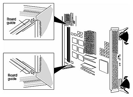
Engage the edges of the SP in the board guides and slide the SP into chassis until the ejectors engage with the chassis edge, as shown in Figure 6-9.
Press both ejectors at the same time until they lock and the SP moves further into the chassis.
If the SP is a Sauna, enable its power by sliding the switch to the Enable position.
Immediately close and lock the fan module as shown in Figure 6-1 and Figure 6-2.
Remove and store the ESD wrist band.
If you installed a replacement SP, what you do next depends whether the storage system contains one or two SPs, and whether you powered off the storage system and host.
If the storage system has one SP, reboot IRIX on the Challenge server.
If you powered off the Challenge RAID and Challenge server, power them on and reboot IRIX.
If you installed an add–on SP, connect the SCSI cable and SCSI terminator plug, as described in Chapter 3 in this guide.
If you upgraded an SP with cache memory, set up storage-system disk caching as described in Chapter 4 in this guide.
Note: For caching, both SPs must have the same amount of cache memory in order for caching to be preserved in the event of shutdown or other power loss.
When you replace or add an SP, you must install the memory modules in the SIMM connectors on the replacement or add–on SP's printed-circuit board.
Silicon Graphics supports only 8 MB and 64 MB memory configurations:
in the 8 MB configuration, two SIMMs of 4 MB each are installed on each SP PC board
in the 64 MB configuration, four SIMMs of 16 MB each are installed on each SP PC board
| Caution: For caching, both SPs must have the same amount of cache memory in order for caching to be preserved in the event of shutdown or other power loss. In storage systems with two SPs, both SPs must be of the same type (both Sauna or both Phoenix). |
If the Challenge RAID has one SP, you can install a second one while the storage system is running and configure it into the RAID array system. When both SPs are installed and configured, you can replace either SP while the storage system is running.
To upgrade an existing 8 MB memory configuration to a 64 MB configuration (required for caching), remove the existing SIMMs on the existing SP board, populate it fully with four 16 MB SIMMs, and reinstall the board; insert four 16 MB SIMMs onto the new SP board and install the board.
| Note: You may find two 1 MB SIMMs on the Sauna SP board instead of two 4 MB SIMMs. |
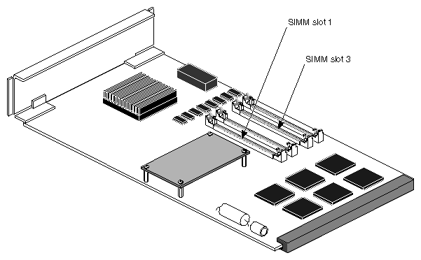
The SP must have one or two pairs of memory modules, and the modules in each pair must have the same capacity. If the SP has only one pair of modules, they must be in the SIMM1 and SIMM3 connectors on the Sauna SP printed-circuit board, as shown in Figure 6-10.
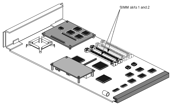
On the Phoenix board, the modules are in connectors 1 and 2 (numbered from the bottom up), as shown in Figure 6-11.
To install SP memory modules, follow these steps:
Run raid5 getcache to determine if caching is enabled. If it is enabled, make sure both SPs are powered on; check the status lights or run raid5 getcrus (see Appendix B for information).
If caching is enabled, disable it by entering
raid5 -d device setcache 0
To make sure that cache state is set to enabled, enter
raid5 -d device getcache
Look for Cache State: Enabled in the output of this command.
Read Section 5.1.1, "Avoiding Electrostatic Discharge (ESD) Damage," in Chapter 5.
Warning: Some components on the SP become hot during operation. To prevent personal injury, disable the SP's power and do not attempt to remove the SP until you have waited at least five minutes for these components to cool. If you are installing memory on both SPs in a system, power off the Challenge RAID storage system.
Disable and remove the SP:
To take a Sauna SP offline, move the power switch to the disable position, as shown in Figure 6-7. Immediately close the fan module. Wait five minutes for the SP to cool in the chassis before removing it and placing it on a static-free work surface.
Attach the clip of the ESD wrist band (strap) to the ESD bracket on the bottom of the storage system (see Figure 5-3 and Figure 5-4 in Chapter 5), and put the wrist band around your wrist with the metal button against your skin. Pull both ejectors until they unlock and the SP or filler board starts coming out of chassis, as shown in Figure 6-8.
To take a Phoenix SP offline, remove it from the chassis and place it on a static-free work surface. Wait for it to cool before handing it further.
Note: You do not have to power off the system if you are installing a second SP in a system that currently has only one, or if you are replacing only one SP in a system that currently has two configured. Remove the memory modules (and, if the customer has ordered it, the SP board) from their packaging, and place them on a static–free work surface.
If you are upgrading 4 MB SIMMs (or 1 MB SIMMs) to 16 MB SIMMs, remove them following instructions in Section 6.4.2, "Removing SP Memory Modules."
Starting with the memory module in the lowest numbered connector (see Figure 6-10), insert the memory modules:
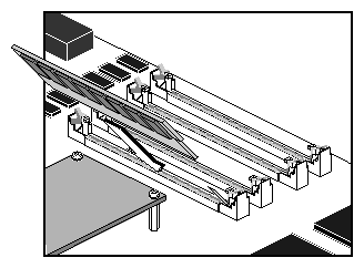
For Sauna, position the memory module in the appropriate SIMM connector at a 20- to 30-degree angle, as shown in Figure 6-12.
Gently push the top of the module up until it locks into the Sauna SIMM connector, as shown in Figure 6-13.
For Phoenix, position the memory module in the appropriate SIMM connector straight down, as shown in Figure 6-14.
Gently push the module to a 20- to 30-degree angle until it locks into the connector, as shown in Figure 6-15.
Install the remainder of the memory modules.
Caution: Do not force the memory modules into the connectors or against the locking tabs. A notch on one end of the module prevents you from inserting it the wrong way. Reinstall the SP board into the SP. If the SP is a Sauna, enable it by pushing the switch to the on position.
If you have powered off the Challenge RAID storage system because you installed memory in both SPs, power it on.
Enable caching in both SPs: see Section 4.12, "Setting Up Caching," in Chapter 4.
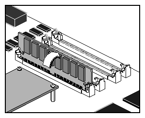
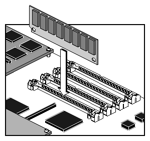
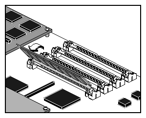
Reinstall the SP following instructions in Section 6.3.3, "Installing an SP."
To ship an SP, remove the memory modules from the printed-circuit board as follows:
Read Section 5.1.1, "Avoiding Electrostatic Discharge (ESD) Damage," in Chapter 5.
Attach the clip of the ESD wrist band (strap) to the ESD bracket on the bottom of the storage system (as shown in Figure 5-3 and Figure 5-4 in Chapter 5), and put the wrist band around your wrist with the metal button against your skin.
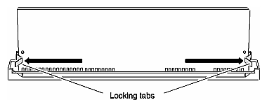
With your thumbs, push out on the memory module's locking tabs. The tabs are indicated in Figure 6-16.
With your fingers, push the module forward until it is released from the tabs. Lift the module out of the connector and place it in its own antistatic package.
Remove and store the ESD wrist band.
If necessary, reboot the operating system software, or use the auto-reassign capability, as explained in Section 6.3.1, "Using the Auto-Assign Capability in the Case of a Failed SP."
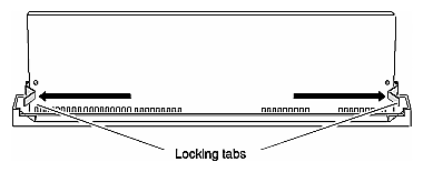
| Note: Do not ship an SP with its memory modules installed. To return a failed or replaced SP, remove the memory modules from the printed-circuit board and place the board and memory modules in shipping containers. |
Upgrade scripts are included on the Challenge RAID software CD and are installed along with the software. To upgrade the FLARE code for a Sauna SP, run
/usr/raid5/sauna7_to_sauna8 |
This script upgrades the FLARE code on the Sauna SP(s) in the system from 7.xx to 8.xx after first disabling caching, if it is enabled. It also loads code to all database disks (A0, B0, C0, and A3).
| Note: When you upgrade a Challenge RAID storage system to FLARE code 8.xx, all prefetch parameters are set to 0, except fort the retention parameter, which is set to equal priority for each existing LUN. You must change these values if you want prefetching to occur for a LUN. |
This section explains how to upgrade the board in an SP from Sauna to Phoenix and how to upgrade the FLARE code to version 8.50 through 8.99, as required by the Phoenix SP. The process consists of
upgrading and testing the FLARE code
moving Sauna SIMMs to the Phoenix SP board
testing the upgrade
| Note: For upgrading from Sauna to Phoenix, it is highly recommended that you use an ASCII terminal or PC connected to the Challenge RAID serial port. When the Phoenix firmware comes up, it shows information for the database drives (A0, B0, C0, and A3). |
| Caution: The storage system is automatically rebooted after the code is downloaded to the SP(s). Do not follow the steps below until you have unmounted any filesystems or partitions on the storage system. |
Upgrade scripts are included on the Challenge RAID software CD and are installed along with the software. To change the FLARE code when upgrading from Sauna to Phoenix, follow these steps:
Determine the FLARE code currently on the SPs:
/usr/raid5/raidcli getagent
If the FLARE code is 7.xx, run the following command to upgrade it to FLARE 8.xx for Sauna (8.00 through 8.49):
/usr/raid5/sauna7_to_sauna8
If the FLARE code is 8.xx (or after you complete step 2), run the following command to upgrade it to FLARE 8.xx for Phoenix (8.50 through 8.99):
/usr/raid5/sauna8_to_phoenix8
This script disables caching, if it is enabled, and then attempts to upgrade the FLARE code from Sauna 8.xx to Phoenix 8.xx on a database disk, in this order: B0, C0, or A3). The script does not update the FLARE code on disk A0, so that it has usable code in case the upgrade fails. Note that this upgrade script works differently from that for the Sauna 7 -to-Sauna 8 upgrade.
Wait five to ten minutes. Halt the system, and then restart the RAID agent:
/etc/init.d/raid5 stop
/etc/init.d/raid5 start
Test the upgrade by using raidcli getagent to make sure the communication path still works and the device to which the code was downloaded can still be seen.
Follow these steps to install the SIMMs from the existing Sauna board onto the new replacement Phoenix board:
After the FLARE code is upgraded and tested as successful, stop the RAID agent:
/etc/init.d/raid5 stop
Power off the Challenge RAID storage system.
Remove the system's Sauna SP(s) following instructions in Section 6.3.2, "Removing an SP," earlier in this chapter.
Remove the Phoenix SP board and, if the customer has ordered them, the additional memory modules from their packaging, and place them on a static–free work surface.
On the Sauna board you are replacing, locate the first SIMM module; see Figure 6-10 if necessary.
Use your thumbs to push out on the memory module's locking tabs.
With your fingers, push the first SIMM module forward until it is released from the tabs, which are shown in Figure 6-17.
Lift the module out of the connector.
Insert the SIMM into the first SIMM connector on the Phoenix board. The modules go into connectors 1 and 2 (numbered from the bottom up) on the Phoenix board, as shown in Figure 6-18.
On the Phoenix board, position the Sauna's first SIMM in the first SIMM connector straight down, as shown in Figure 6-19.
Note: A memory module has a notch on one end so that you can insert it only one way. Gently push the module to a 20- to 30-degree angle until it locks into the connector, as shown in Figure 6-20.
Remove the second SIMM from connector 2 on the Sauna board and install it in connector 2 on the Phoenix board following procedures in the preceding steps.
Complete the process for the remainder of the memory modules.
Reinstall the SP into the controller.
Power on the Challenge RAID storage system.
| Note: When you upgrade a Challenge RAID storage system to FLARE code 8.xx, all prefetch parameters are set to 0, except fort the retention parameter, which is set to equal priority for each existing LUN. You must change these values if you want prefetching to occur for a LUN. |
After the Challenge RAID storage system is powered on, restart the RAID agent:
/etc/init.d/raid5 start |
To check whether the revision level is correct, enter
/etc/usr/raid5/raidcli getagent |
In the output of this command, look for the Revision: line, which should show a FLARE code number between 8.50 and 8.99.
| Note: If the database drive that has the original Sauna code fails, replace the failed disk in order to complete the upgrade process. |
If the test is not successful, reverse the upgrade procedure. Follow these steps:
If the database drive that has the Phoenix FLARE code fails, replace the failed disk in order to complete the rest of the steps in this section.
Power off the Challenge RAID storage system.
Remove the Phoenix board from the chassis.
Remove each SIMM and replace it to its original slot on the Sauna SP.
Replace the Sauna in the chassis.
Power on the storage system.
If you upgrade to FLARE 9.xx in a storage system with existing RAID–3 LUNs, the RAID–3 LUNs will work, but will not be FLARE 9.xx RAID–3 LUNs. To make them FLARE 9.xx RAID–3 LUNs, follow these steps:
Back up the data on the RAID–3LUNs.
Allocate storage-system memory to RAID–3, as explained in Section 4.8, "Allocating Memory for RAID-3 LUNs," in Chapter 4.
Unbind the RAID–3 LUNs.
Rebind the RAID–3 LUNs.
These LUNs are now FLARE 9.xx RAID–3 LUNs.
Reload data onto the RAID–3 LUNs.
| Note: Once you have loaded FLARE 9.xx and have bound RAID–3 LUNs, do not load an earlier FLARE revision. If you do so, these FLARE 9.xx RAID–3 LUNs appear as Unbound in the output of raidcli getdisk. If you then reload FLARE 9.xx, the status of these RAID–3 LUNs changes to Bound and Not Assigned (in the GUI, LUNs not owned by an SP) and the storage-system RAID–3 memory is 0 MB in size. To use these RAID–3 LUNs, you must resize the storage-system RAID–3 memory to the size equal to the total of the RAID–3 memory assigned to each RAID–3 LUN. (To determine RAID-3 memory, use raidcli getlun.) |