This chapter explains:
setting up a Challenge RAID rack
opening the rear door of a Challenge RAID rack
reseating subassemblies
labeling disk modules
cabling RAID configurations
setting SCSI IDs for SPs
cabling an additional Challenge RAID storage system on a SCSI–2 bus channel
setting SCSI IDs for SPs in a second Challenge RAID on the same SCSI–2 bus channel
powering on the Challenge RAID storage system
A Phillips-head and a medium or thin flat-blade screwdriver are required. For maintenance and troubleshooting, a laptop (or ASCII terminal) is required. For unbolting the Challenge RAID rack, you need a 9/16-inch nut driver; the ratcheting type is recommended.
 | Note: For instructions on installing an additional chassis assembly in a Challenge RAID rack, see Chapter 5, "Maintaining and Upgrading Disk Modules." |
To set up a Challenge RAID rack, follow these steps:
Remove the cardboard cover and verify that all parts are present and in good condition. If they are not, notify the shipper of the missing parts.
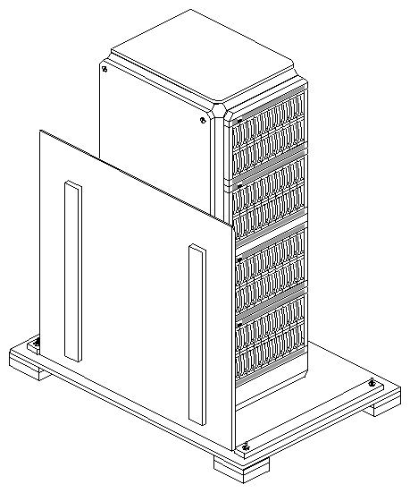
Notice the ramp attached to the pallet by a piece of flexible plastic. You'll use this ramp later to move the rack off the pallet.
Leave the rack still bolted to the pallet and move it to or near the position where the customer wants it.
Note: The rack can be very difficult to move on rugs; it is much easier to move it while it is still bolted to the pallet. A fully loaded rack system weighs just under 900 pounds. Remove the bubblewrap. Remove the flexible plastic that attaches the ramp to the pallet; move the ramp out of the way if necessary.
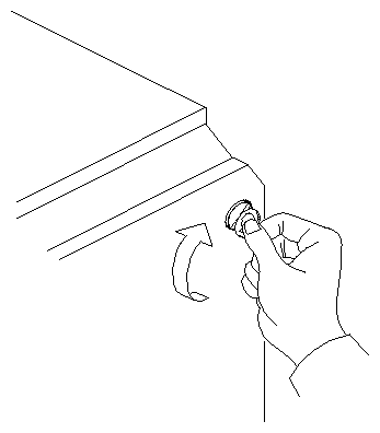
To remove the Challenge RAID rack side panels, which is necessary for unbolting the rack from the pallet, use a coin to open the latches that hold the side panels in place, as shown in Figure 3-2. Each panel has two latches, one in each upper corner.
Remove both side panels. It is not necessary to remove the rear door for this procedure.
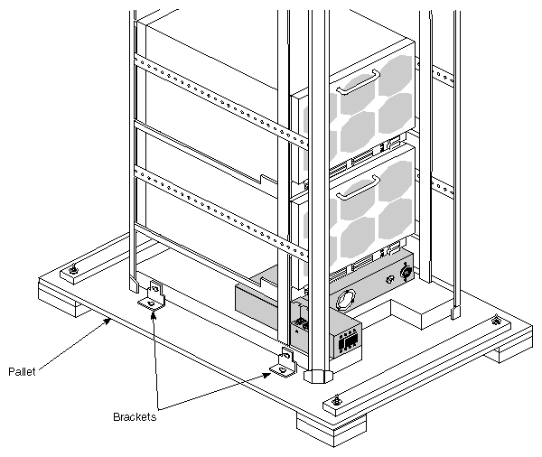
The rack is attached to the pallet with four brackets, two on each side; Figure 3-3 shows brackets on one side.
Note: Figure 3-3 shows the rack's rear door removed, but it is not necessary to remove it for this procedure. Using a 9/16-inch nut driver, remove the nuts on all brackets; remove the brackets.
Position the ramp at the side of the pallet with one edge resting securely on the two feet of the pallet. Carefully move the rack off the pallet using the ramp.
 | Warning: At least two persons are required to move a Challenge RAID rack. Do not undertake this procedure unless another qualified Silicon Graphics SSE is available to help. |
To check chassis assemblies in the rack, you must open the rear door.
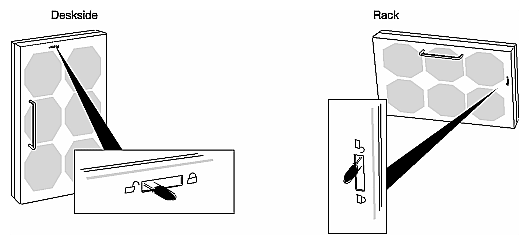
To open the rear door of the rack, use a thin or medium flat-blade screwdriver, as shown in Figure 3-4.
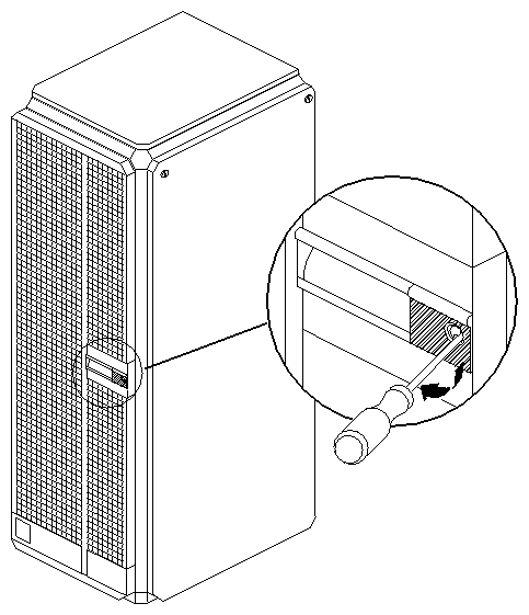
Move the screwdriver to the left to open the door.
| Note: If you must remove the rear door entirely for any procedure, rehanging the rear door might require a second person because of the difficulty of lining up the door's three pinlocks. |
Make sure all components of the Challenge RAID storage system are firmly seated in their sockets. Follow these steps:
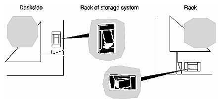
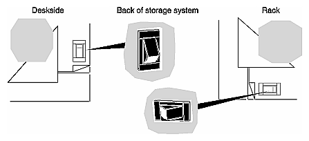
If the Challenge RAID storage system is turned on, power it off. See Figure 3-5.
On the back of the Challenge RAID chassis, move the fan module's latch to the UNLOCK position, as indicated in Figure 3-6.
Swing open the fan module.
Check that these units are firmly seated:
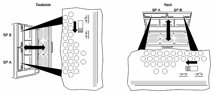
Figure 2-4 and Figure 2-5 in Chapter 2 diagram the location of these components for a deskside and rack system, respectively.
Disk modules are discussed in the next section in this chapter.
Close the fan module by moving its latch to the LOCK position.
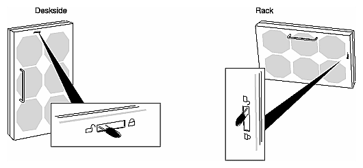
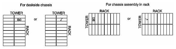
Each disk module has a sticky label so that the installer or owner can label the disk module according to its the slot it occupies in the chassis. On the disk module label is a matrix that corresponds to the possible disk positions in the chassis. Figure 3-7 shows the disk module label.
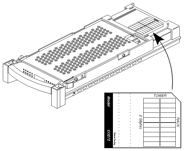
Labeling disk modules consists of marking this matrix. You can either write the slot position on the label in the corresponding place on the matrix or make a check mark in the position to indicate the slot that the disk module occupies. Figure 3-8 shows these two ways of labeling disk module B0.
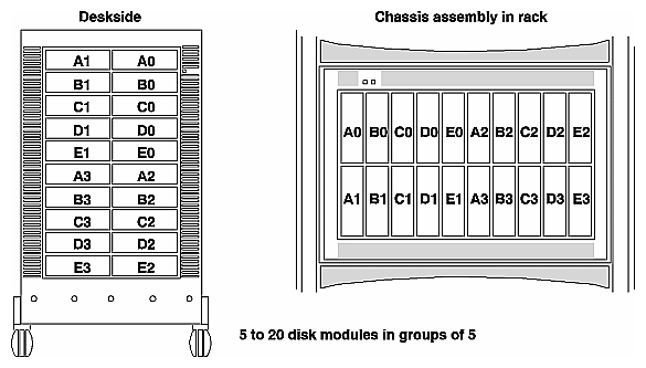
For reference, Figure 3-9 diagrams all disk module locations.
To label disk modules, follow these steps:
Pull out the disk drive module that is in slot A0. Mark the label A0 in the space indicated in Figure 3-7. Reinsert and reseat disk drive module A0.
Pull out the disk drive module directly beneath it, that is, the drive module on the right side that is second from the top. In the corresponding space on the matrix, mark its label B0, as shown in Figure 3-8.
Reinsert and reseat disk drive module B0. Pull out the disk drive module directly beneath it, that is, the drive module on the right side that is third from the top. In the corresponding space on the matrix, mark its label C0.
Pull out, label, and reseat disk drive module D0; pull out, label, and reseat disk drive module E0.
Pull out the disk drive module that is in the upper left slot. In the upper left space on the matrix, mark its label A1; reinsert and reseat it. Repeat this procedure for disk modules in slots B1, C1, D1, and E1.
If there are disk modules in the lower half of the chassis, pull out the disk drive module that is in the sixth slot from the top, on the right. In the corresponding space on the matrix, mark its label A2; reinsert and reseat it. Repeat this procedure for disk modules in slots B2, C2, D2, and E2.
If there are disk modules in the remaining bus in the chassis, pull out the disk drive module that is in the sixth slot from the top, on the left. In the corresponding space on the matrix, mark its label A3; reinsert and reseat it. Repeat this procedure for disk modules in slots B3, C3, D3, and E3.
Table 3-1 summarizes Challenge RAID configurations.
Table 3-1. Challenge RAID Configurations
Configuration | Host | SCSI-2 Interface | SCSI-2 Bus | SP |
|---|---|---|---|---|
Basic | 1 | 1 | 1 | 1 |
Dual-interface/dual-processor | 1 | 2 | 2 (1 per server) | 2 |
Split-bus | 2 | 2 (1 per server) | 2 (1 per server) | 2 |
Dual-bus/dual-initiator | 2 | 4 (2 per server) | 2 (1 per server) | 2 |
This section explains cabling each of these configurations.
The Challenge RAID basic configuration consists of one Challenge server with one SCSI–2 interface, one SCSI–2 bus, and one Challenge RAID storage system or chassis assembly with one storage-control processor (SP A). Figure 3-10 diagrams the basic configuration.
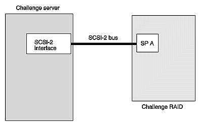
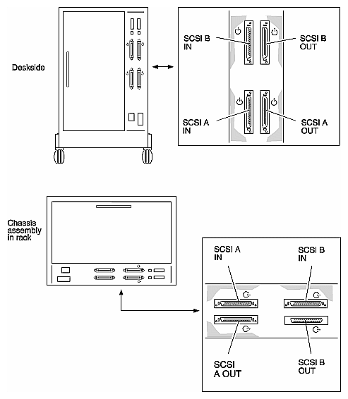
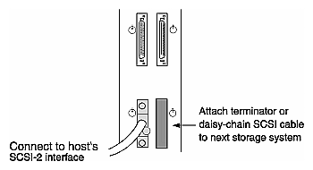
Figure 3-11 shows the location of SCSI-2 bus connectors on the Challenge RAID chassis.
To cable the basic configuration, follow these steps:
Power off the Challenge server, if it is not already powered off.
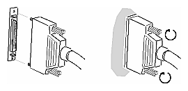
Connect the SCSI cable to the SCSI A in connector as shown in Figure 3-12 and Figure 3-13, making sure the cable is fastened securely.
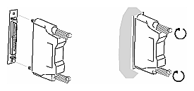
Connect a terminator plug to the SCSI B in connector as shown in Figure 3-14, making sure the terminator plug is fastened securely.
 | Caution: SCSI terminators must be in place at all times during operation. Removing them causes the storage system to crash. |
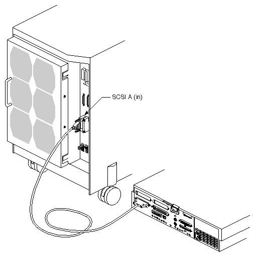
Figure 3-15 shows a typical hookup for a Challenge S.
The Challenge RAID dual-interface/dual-processor configuration consists of a Challenge server with two SCSI–2 interfaces, two SCSI–2 buses, and a Challenge RAID storage system or chassis assembly with two storage-control processors (SP A and SP B). Figure 3-16 diagrams an example of this configuration.
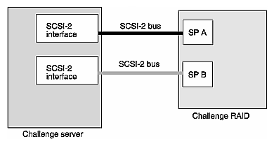
To cable the dual-interface/dual-processor configuration, follow these steps:
Power off the Challenge server (if necessary).
Arbitrarily name one interface in the Challenge server first interface and the other second interface.
Cable the first interface to the SCSI A in connector (the lower SP) in the Challenge RAID storage system. See Figure 3-11 for the location of the SP sockets.
Cable the second interface to the SCSI B in connector (the upper SP) in the Challenge RAID storage system. Connect the SCSI cable as shown in Figure 3-13, making sure all cables are fastened securely.
The Challenge RAID split-bus configuration consists of two Challenge servers, each with one SCSI–2 interface, two SCSI–2 buses (one per Challenge server), and a Challenge RAID storage system or chassis assembly with two SPs. Figure 3-17 diagrams an example of this configuration.
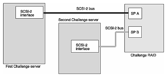
To cable the split-bus configuration, follow these steps:
Power off the Challenge servers (if necessary).
Consulting the customer, designate one Challenge server first server and the other second server.
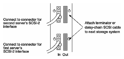
Cable the first server to the SCSI A in connector (the lower SP) in the Challenge RAID storage system. See Figure 3-11 for the location of the SP sockets.
Cable the second server to the SCSI B in connector (the upper SP) in the Challenge RAID storage system. Connect the SCSI cable as shown in Figure 3-13, making sure all cables are fastened securely.
Figure 3-18 diagrams connecting Challenge RAID to the SCSI bus in a split-bus configuration.
The Challenge RAID dual-bus/dual-initiator configuration consists of
two Challenge servers, each with two SCSI–2 interfaces
four SCSI–2 buses (two per Challenge server)
Challenge RAID storage system or chassis assembly with two SPs
Figure 3-19 diagrams an example of this configuration, which is required for the Oracle Parallel Server and IRIS FailSafe products.
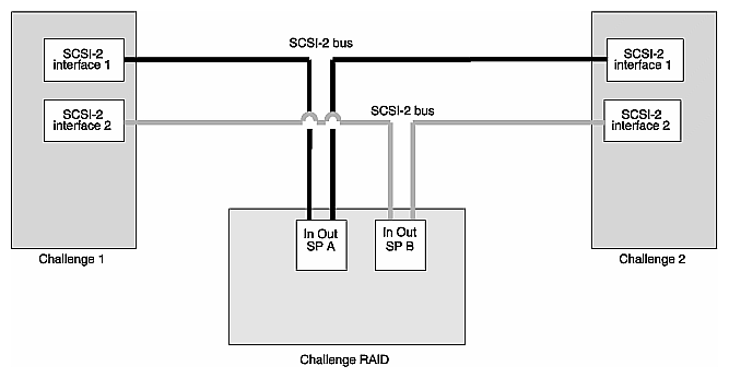
To cable the dual-bus/dual-initiator configuration, follow these steps:
Power off the Challenge servers (if necessary).
Consulting the customer, designate one Challenge server as the first server and the other as the second server.
Cable the first SCSI interface of first server to the SCSI A in connector (the lower SP) in the Challenge RAID storage system. See Figure 3-11 for the location of the SP sockets.
Cable the first SCSI interface of the second server to the SCSI A out connector.
Cable the second server to the SCSI B in connector (the upper SP) in the Challenge RAID storage system.
Cable the second SCSI interface of the second server to the SCSI B out connector.
Connect the SCSI cable as shown in Figure 3-13, making sure all cables are fastened securely. Figure 3-20 diagrams connecting Challenge RAID to the SCSI bus in a dual-bus/dual-initiator configuration.
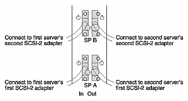
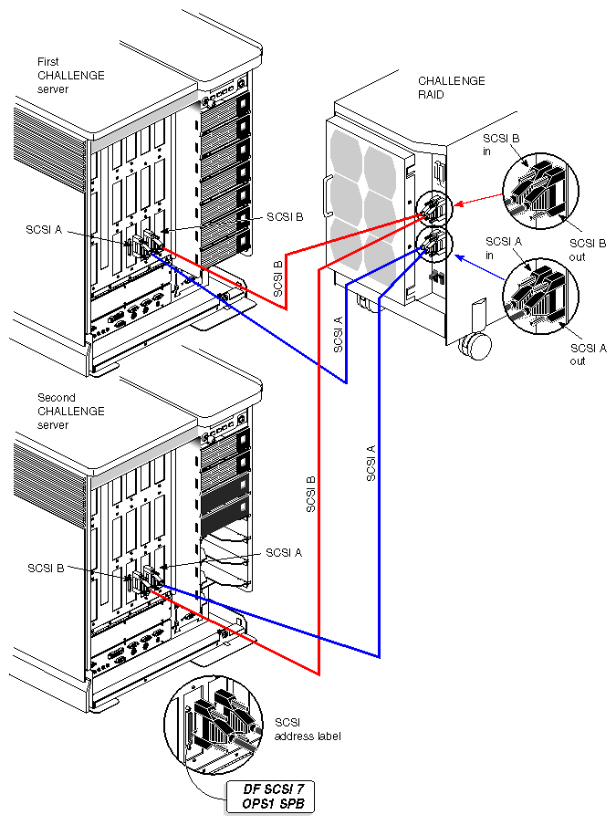
Figure 3-21 shows a typical hookup for an OPS configuration with one Challenge RAID storage system.
Each SP connected to the same SCSI bus channel requires a unique SCSI ID number. The back of the Challenge RAID storage system has two SCSI ID switch packs, as shown in Figure 3-22. One switch pack sets the SCSI ID for SP A, and the other sets the SCSI ID for SP B. Each switch pack has four switches (ID0-ID3).
| Note: To set SCSI IDs for a second Challenge RAID storage system on the same bus channel, see "Setting SCSI IDs for SPs in a Second Challenge RAID on the Same SCSI–2 Bus Channel," later in this chapter. |
Set the SCSI ID switches for SP A and SP B to the lowest unused ID number. Figure 3-22 indicates the ID switches. In this example, SP A is set to 0 and SP B is set to 1.
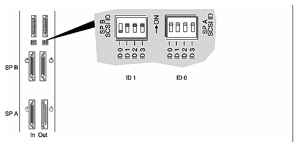
Table 3-2 charts ID switch settings.
SCSI ID Number | Switch Number |
|
|
|
|---|---|---|---|---|
| ID 0 | ID 1 | ID 2 | ID 3 |
1 | Off | On | On | On |
2 | On | Off | On | On |
3 | Off | Off | On | On |
4 | On | On | Off | On |
5 | Off | On | Off | On |
6 | On | Off | Off | On |
7 | Off | Off | Off | On |
8 | On | On | On | Off |
9 | Off | On | On | Off |
10 | On | Off | On | Off |
11 | Off | Off | On | Off |
12 | On | On | Off | Off |
13 | Off | On | Off | Off |
14 | On | Off | Off | Off |
15 | Off | Off | Off | Off |
| Note: Make sure that you set each SP to its own ID number—an ID number that is not used by any other device on the same SCSI bus. You can use any unused SCSI device number except 0. |
For Challenge RAID rack storage systems, or for customer sites with more than one deskside Challenge RAID storage system, follow instructions in this section to cable more than one Challenge RAID storage system on the same SCSI-2 bus channel.
Once you have connected the first Challenge RAID to the host, connect a second one by following these steps:
Add the length of all SCSI cables to be used in the final configuration to make sure that it does not exceed the recommended maximum of 60 feet (18.3 meters). Include 3 feet for the Challenge chassis and 8 feet for each RAID chassis assembly. Use Figure 3-23 as a guide.
Caution: Although the SCSI bus absolute length limit is 80 feet, exceeding 60 feet on the SCSI bus is not recommended. When cable lengths exceed 60 feet, problems can occur on the SCSI mezzanine card, the IO4B board, or both. In Figure 3-24, locate the column of diagrams labeled "First Challenge RAID System."
Circle the configuration for the Challenge RAID system that is already connected to the SCSI–2 bus channel.
For example, if the first storage system configuration is the basic configuration, circle this configuration under "First Challenge RAID System," as shown in Figure 3-25.
In the column of diagrams labeled "Second Challenge RAID System" in Figure 3-24, circle the configuration for the second Challenge RAID to which you want to connect the first storage system.
For example, circle the dual-interface/dual-processor configuration under "Second Challenge RAID System," as shown in Figure 3-25.
In your configuration, if the SCSI A channel of the first storage system is used (a SCSI cable is plugged into its in connector), but its out connector is not used (no SCSI cable or terminator plug is plugged into it), draw a line from the unused out connector of SCSI A to the end of an input cable of the second storage system. If the second storage system configuration has two available input cables, draw the line to either SCSI A or SCSI B. Which connector you use is entirely up to you.
For example, connect the SCSI A output of the first storage system to the SCSI A input of the second storage system, as shown in Figure 3-25.
In your configuration, if the SCSI B channel of the first storage system is used (a SCSI cable is plugged into its in connector), but its out connector is not used (no SCSI cable or terminator plug is on it), draw a line from the unused out connector of SCSI B to the end of an input cable of the second storage system. If no input cable is available on the second storage system, circle the SCSI B out connector of the first storage system to indicate that you must install a SCSI terminator plug in the connector.
For example, the SCSI B in connector of the first storage system has no input bus connected to it; therefore you cannot use it, as shown in Figure 3-25.
If the second storage system has an unconnected input cable, connect it directly to a SCSI bus connector on the server. Write "To server" at the end of this cable.
The basic configuration requires one SP installed in slot SP A. The others require two SPs. If you need to install or move an SP, follow the steps in Section 6.3, "Replacing or Adding an SP," in Chapter 6.
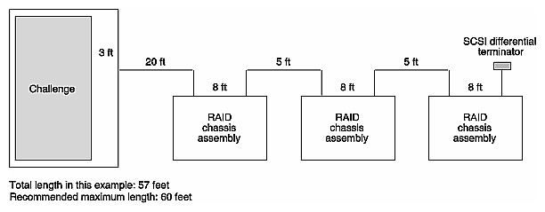
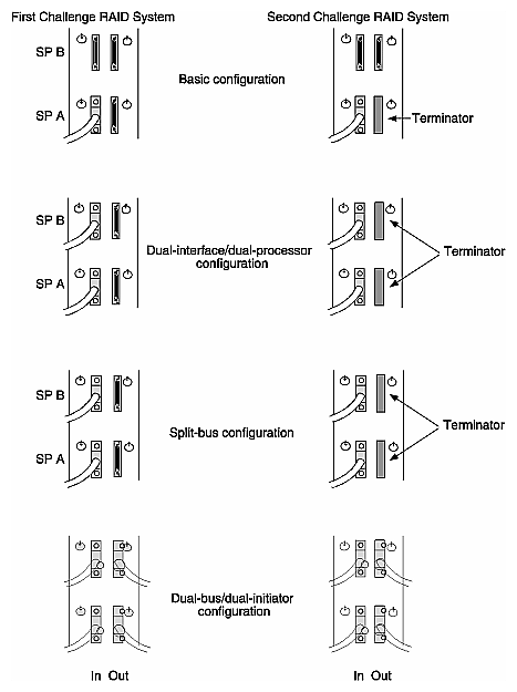
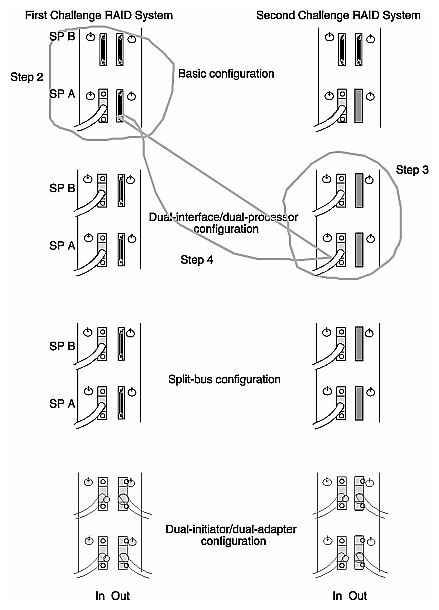
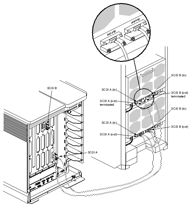
Figure 3-26 shows SCSI buses A and B hooked up to two RAID chassis assemblies in a Challenge RAID rack storage system.
Figure 3-26. Connecting SCSI Buses A and B to Two RAID Chassis Assemblies in a Challenge RAID Rack Storage System
 |
Set the SCSI ID switches for the configuration you are installing; Table 3-3 presents suggested settings.
Table 3-3. Recommended SCSI ID Settings for SPs in Second Challenge RAID on a SCSI-2 Bus Channel
Dual-SP and Dual-Initiator Configuration for First Storage System: SPs on Same SCSI-2 Channel | Any Other Configuration for the First Storage System |
|---|---|
SCSI ID 1 for the first SP A | SCSI ID 1 for the first SP A and SP B |
SCSI ID 2 for the second SP B | SCSI ID 2 for the second SP |
SCSI ID 3 for the third SP | SCSI ID 3 for the third SP |
SCSI ID 4 for the fourth SP | SCSI ID 4 for the fourth SP |
The recommended SCSI ID settings are just suggestions. You can set the SCSI ID for an SP to any number you want except for the following:
Never set two SPs connected on the same bus to the same ID number. Each SP or device on a SCSI–2 bus channel must have a unique SCSI ID number.
Use any unused SCSI device number except 0.
To power on the system, follow these steps:
Make sure that the Challenge RAID power switch is off.
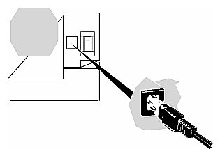
Connect the power cord to the storage system. Plug the other end of the power cord into an AC power outlet. See Figure 3-27.
Turn on the storage system's power.
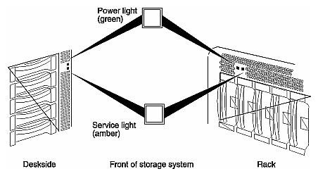
The green power light on the front of the Challenge RAID storage system turns on and the fans rotate. See Figure 3-29.
If the busy light on none of the drive modules lights up, make sure that the power for each SP is enabled. Move the fan module's latch to the UNLOCK position, as indicated in Figure 3-30.
Swing open the fan module. On a Sauna SP, move the power switch to the enable position, as shown in Figure 3-31.
Note: The Phoenix SP does not have a power switch. Close the fan module by swinging it closed, and then moving the latch to the LOCK position.
Power on the Challenge server(s).