This chapter explains how to label and partition physical disks, and create and mount disk filesystems. It explains how to use raidcli, the command-line interface (formerly raid5), in an IRIX shell to accomplish disk management tasks. This chapter explains
installing the Challenge RAID software
creating a configuration file
starting the agent
using raidcli commands
getting the device name with raidcli getagent
unbinding disks
planning the bind
binding disks into RAID units
enabling command-tagged queuing
understanding dual processors, load balancing, and device names
setting up caching, if the customer desires (system with two SPs only)
A laptop or ASCII terminal is required for maintenance or troubleshooting.
Note the following:
If the Challenge RAID storage system is not connected to Challenge server during the software install process, the device nodes will not be created.
If a second (add-on) Challenge RAID is connected later, the device nodes must be created by changing to the /dev directory and entering ./MAKEDEV dks scsi.
Follow these steps:
Make sure the Challenge server is running IRIX version 5.3 or IRIX 5.3 with XFS and applicable patches. If it is not, upgrade the software using patches included in the current Required Patches List, including those on the patches CD-ROM (813-0412-001) included with the Challenge RAID product.
Load the Challenge RAID software from the RAID CD-ROM (813-0322-004). The Challenge RAID software images are created in inst format; thus, they require that the inst program be used. Installation software and instructions are included with the standard Silicon Graphics software products.
After quitting inst, reboot the system to start the software.
The Challenge RAID agent, which interprets commands from the command line interface for the Challenge RAID storage system, uses the configuration file /usr/raid5/raid5-agent.config. This file contains
description specification: list of objects that can be specified in the file
RAID specification: format for RAID devices
user specification: list of users allowed to perform write operations; root is the default
poll specification: a value that determines whether polling is performed and whether the agent stores a copy of the log in its memory
This file is self-documenting and contains samples. Edit it to suit the customer's needs. /usr/raid5/raid5-agent.config.proto is a example configuration.
RAID administration is through a daemon called the RAID agent. This agent communicates to the Challenge RAID storage system through /dev/scsi device nodes and interprets commands from the command line interface for the SCSI device, namely, the storage system. When the storage system is installed, the startup script starts the agent.
 | Note: Because the agent opens the /dev/scsi device nodes on an exclusive basis, no other process can open them. |
The agent interprets commands from the command line interface for the SCSI device, namely, the Challenge RAID storage system. The agent can determine the existence and ownership of all LUNs in the RAID, regardless of ownership.
To start the agent manually, turn on the Challenge RAID storage system as explained in Chapter 3. Start the Challenge RAID software:
/etc/chkconfig -f raid5 on /etc/init.d/raid5 start |
If the agent is not active, the Challenge RAID storage system is not available to the server and an error message appears. For error conditions and solutions, see Appendix C, "Troubleshooting." Error messages from the agent are not reported to the console, but are stored in the syslog file.
The raidcli command sends Challenge RAID storage management and configuration requests to an application programming interface (API) on the Challenge server. For the raidcli command to function, the agent—an interpreter between the command line interface and the Challenge RAID storage system—must be running.
| Note: A graphical user interface, RAIDGUI, is also available; it is documented extensively in the CHALLENGE RAID Owner's Guide, revision 007-2532-006 on. |
The synopsis of the raidcli command is
raidcli [-vp] [-d device] parameter [optional_arguments] |
In this syntax, variables and options mean:
The environment variable RaidAgentDevice is the default value for the device when none is specified with the -d flag. If RaidAgentDevice is not set and no -d switch is present, an error is generated on all commands that need device information. For example:
setenv RaidAgentDevice sc4d2l0 setenv RaidAgentDevice /dev/scsi/sc4d2l0 |
The /dev/scsi prefix is optional.
Use the getagent parameter with the command line interface raidcli to display information on devices controlled by the API:
raidcli getagent |
Following is sample output for one device; normally, the output would give information on all devices.
Agent Rev: 1.55 Name: phx-SPB-sc6d2 Desc: TOWER 1 Node: sc6d2l0 Signature: 0xc4aa1c00 Peer Signature: 0x0 Revision 9.2.91, Model: 7305 SCSI Id: 1 Prom Rev: 1.55.0 SP Memory: 32 Serial No: 96-0525-6 |
All raidcli commands except raidcli getagent require specifying the device; use the string at Node in the getagent output to specify the device. For a complete explanation of this output, see Appendix B, "The raidcli Command-Line Interface."
The disk modules in the Challenge RAID are configured as RAID-5 units at the factory. To bind disks at other RAID levels, you must unbind them first. Unbinding a LUN divides it into its constituent disk modules, allowing you to rebind the modules in any valid configuration the customer wants.
Unlike binding, unbinding takes only a few moments. You can unbind a LUN only if it is broken or bound, that is, only if its modules are in the Enabled or Broken state. You can unbind a hot spare only if it is on standby.
To unbind a disk, use the unbind parameter with the raidcli command. Follow these steps:
In an IRIX window, use raidcli getagent to get the device name (node number).
If necessary, use raidcli getdisk to verify the disk positions. See "getdisk" in Appendix B for details.
Use raidcli unbind to unbind the individual disk units:
raidcli -d device unbind lun-number [-o]
In this syntax, device is the device name as returned by getagent and lun-number is the number of the logical unit to unbind. The -o flag specifies that the user is not prompted for permission. The unbind parameter has no output.
The following example destroys LUN 3 without prompting for permission:
raidcli -d sc4d2l0 unbind 3 -o |
For more information on the unbind parameter, see "unbind" in Appendix B.
filesystem capacity considerations for RAID
determining RAID levels
planning a RAID-3 bind
| Note: The information in this section is also included in Chapter 4 of the CHALLENGE RAID Owner's Guide. |
You can bind as many as 16 drives in a LUN; for 4 GB drives, this capacity totals 64 GB. However, filesystems have capacity limits that must be taken into account.
For IRIX 5.3 and earlier, an EFS filesystem is a maximum of 8 GB.
For IRIX 5.3 and earlier, an XFS filesystem can be over a terabyte; however, the device parameter portion of the volume header is limited. Because values cannot exceed the number of bits allocated for each of the fields in the volume header (sec/trk, trks/cyl, #cyls), decrease the #cyls to within the 16-bit value available and increase one of the other fields.
To determine allowed capacity limits for an IRIX release, view the header files dvh.h and dksc.h in /usr/include/sys.
Before you create LUNs, consult with the customer to plan the RAID levels. The LUNs are bound in a particular order, depending on the RAID level for each one:
first: RAID-1_0
next: RAID-0, RAID-3, or RAID-5
next: RAID-1
last: individual disk units and hot spares
Note the rules outlined in Table 4-1 for binding disk modules into LUNs.
RAID-3 for systems with SPs that have firmware revision level 9.0 and higher (SP model 7305) and RAID agent 1.55 and higher has enhanced performance compared to previous firmware revision levels. This version of RAID-3 ("fast" RAID-3) has specific memory characteristics and requirements, which are explained in this section. (To determine revision level, see "getsp" in Appendix B.)
An SP's memory is divided into RAID–3 space, storage-system buffer space, write cache space, and read cache space. You allocate RAID-3 memory before binding LUNs; this chapter gives specific steps for each user interface.
Storage-system buffer space in a PowerPC-based SP is always 4 MB. You can allocate all or part of the remaining memory for RAID-3 and other uses. For example, if the SP in a system has 16 MB of memory, memory can be allocated for:
system buffers (4 MB)
read or write cache for non-RAID-3 LUNs, if any
any previously bound RAID-3 LUNs, if any
RAID-3 LUNs
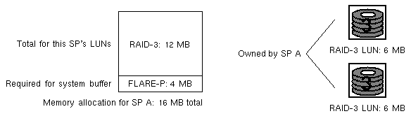
For RAID-3 LUNs, you allocate RAID-3 memory instead of read or write cache. For example, if a system with one 16-MB SP system is to contain two RAID–3 LUNs only, you can allocate all 12 MB (after the 4 MB required for system buffers) to RAID–3 memory.
You then split this memory between the two LUNs, assigning 6 MB to each. Figure 4-1 diagrams this example.
In systems with two SPs, the amount of SP memory allocated for RAID-3 must be the same for each SP.
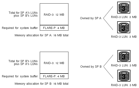
A RAID-3 LUN uses the RAID-3 memory on the SP that owns it. Therefore, if failure occurs and ownership of the failed SP is transferred, the surviving SP must have enough memory for its own LUNs and that of the failed SP. Figure 4-2 diagrams an example.
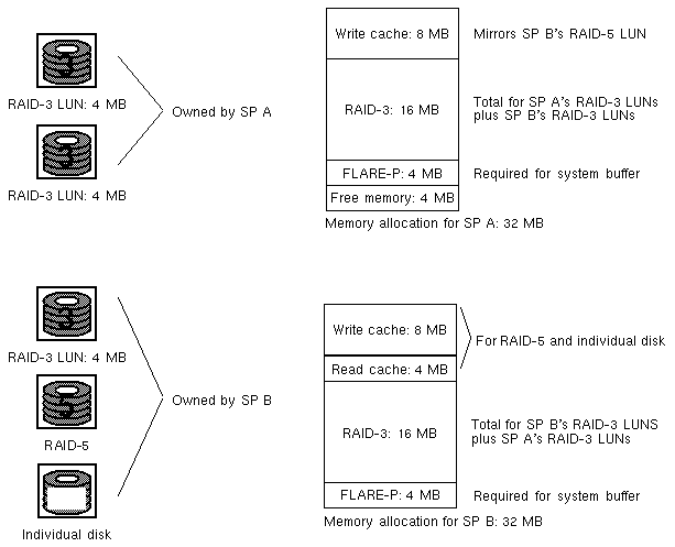
For failover systems, both SPs should have the same amount of physical memory. If the two SPs in a system have different amounts of physical memory, ownership of RAID-3 LUNs transfers from a failed SP to a working SP only if the working SP has
4 MB required for system buffers
memory allocated for read or write cache for non-RAID-3 LUNs, if any
total RAID-3 memory for its RAID-3 LUNs and the other SP's RAID-3 LUNs
minimum of 4 MB for each RAID-3 LUN
Figure 4-3 diagrams an example.
To get the most out of a storage system with RAID-3, follow these guidelines:
Bind all LUNs in the system to RAID-3 only. In a storage system with onlyRAID–3 LUNs, no memory is allocated for storage-system read or write caching; all memory is allocated for RAID-3.
Allocate the maximum of 6 MB of storage-system memory for each RAID–3 LUN. For two RAID–3 LUNs, allocate 12 MB of storage-system memory for the RAID–3 memory partition and 6 MB to each of the two RAID–3 LUNs when you bind them. Since an SP requires 4 MB of storage-system memory for system buffers, each SP needs 16 MB of memory. Failover requires 32 MB.
If the LUNs you are creating are RAID-3 for SP model 7305/firmware revision 9.0 and higher and RAID agent 1.55 and higher, you must allocate a special amount of memory dedicated to RAID-3 before starting the bind. In this revision, RAID-3 is "fast" RAID-3. Use raidcli -d <device> getsp to determine an SP's firmware revision level and model number.
Follow these steps:
| Note: The system cannot be used during allocation of RAID-3 memory. |
Determine the amount of memory you can use for each SP. If necessary, use raidcli getcache to determine each SP's total memory. Look for Raid 3 memory size for spA/spB in the output.
Note: For RAID-3, you must allocate at least 2 MB of RAID-3 memory per LUN for each SP. Failover requires a minimum of 4 MB per LUN for each SP. Quiesce the bus: log users off and back up the system. The system cannot be used during RAID-3 memory allocation.
Make sure read and write caches are disabled and there are no unassigned dirty pages. For example:
raidcli -d sc4d2l0 getcache
In the output, look for these lines:
Cache State: Disabled
...
Unassigned Cache Pages: 0
...
Prct Dirty Cache Pages = 0
...
SPA Read Cache State enabled
SPB Read Cache State enabled
Use raidclisetcache to set the total amount of caching dedicated to RAID-3. (For full details of setcache, see "setcache" in Appendix B.)
Note these guidelines:
Storage-system buffer space in a PowerPC-based SP is always 4 MB. You can allocate all or part of the remaining memory for RAID-3.
Allocating write/read cache memory decreases the amount of memory available for RAID-3 memory. If the storage system uses RAID-3 LUNs only, no write and read caches are used; do not allocate memory for this purpose.
Each SP must have at least 2 MB allocated for RAID-3. For maximum RAID-3 performance, allocate 6 MB of RAID-3 memory for each RAID-3 LUN you want to bind.
For failover, each SP must have the same amount of memory allocated. Furthermore, the total memory you set for each SP must include memory for this SP plus that of the other SP. See Section 4.7.3, "Planning a RAID-3 Bind," earlier in this chapter.

Caution: Setting RAID-3 cache memory reboots the firmware. Make sure the system is not in use before proceeding. The following example sets the RAID-3 cache to 6 MB:
raidcli -d sc4d2l0 setcache 1 -r3 6
For failover, RAID-3 memory assigned to each SP must be the total of the SPs used in the failover system. This example sets the RAID-3 cache for a system in which each SP has 6 MB:
raidcli -d sc4d2l0 setcache 1 -r3 12
When you press <Enter> to complete the command, a message informs you that the SPs will be rebooted.
Wait two minutes; then stop and restart the RAID agent:
/etc/init.d/raid5 stop
/etc/init.d/raid5 start
Create LUNs for each SP using the -r3 option to allocate RAID-3 memory; for example:
raidcli -d sc4d2l0 bind r3 2 a2 b2 c2 d2 e2 -r3 4
raidcli -d sc4d2l0 bind r3 3 a3 b3 c3 d3 e3 -r3 4
In this example:
r3 sets the RAID level to RAID-3
2 sets the LUN number to 2; 3 sets the LUN number to 3
a2 b2 c2 d2 e2 binds disks to LUN 2 and a3 b3 c3 d3e3 binds disks to LUN 3; five disks are required for each RAID-3 LUN
-r3 4 sets RAID-3 cache memory for each LUN to 4 MB
For failover, you must set a total of the memory for this SP's LUNs plus that of the other SP; each SP must have the same amount of memory allocated. That is, the RAID-3 cache memory you set with raidclibind -r3 for each SP must be half the amount you have set with raidcli setcache -r3 in step 4. See Section 4.7.3, "Planning a RAID-3 Bind," earlier in this chapter.
The physical disk unit number is also known as the logical unit number, or LUN. The LUN is a decimal number between 0 and 7. You can bind disks into RAID levels 0, 1, 1_0 (0+1), 3, or 5.
To group physical disks into a RAID unit, use
raidcli -d device bind raid-type lun-number disk-names [optional-args] |
Variables in this syntax are explained below.
| Note: If the LUN you are creating is RAID-3, you must allocate SP memory before starting the bind; see Section 4.8, "Allocating Memory for RAID-3 LUNs." |
The optional arguments are as follows.
| -r rebuild-time | Maximum time in hours to rebuild a replacement disk. Default is 4 hours; legal values are any number greater than or equal to 0. A rebuild time of 2 hours rebuilds the disk more quickly, but degrades response time slightly. A rebuild time of 0 hours rebuilds as quickly as possible but degrades performance significantly. If the customer requires fast response time and they want to minimize degradation to normal I/O activity, enter a longer period of time, such as 24 hours. The customer can change the rebuild time later without damaging the information stored on the physical disk unit. | |
| -s stripe-size | Number of blocks per physical disk in a RAID-5 stripe. Default is 128; legal values are any number greater than 0. The smaller the stripe element size, the more efficient the distribution of data read or written. However, if the stripe size is too small for a single host I/O operation, the operation requires accessing two stripes, thus causing the hardware to read and/or write from two disk modules instead of one. Generally, it is best to use the smallest stripe element size that will rarely force access to another stripe. The default stripe element size is 128 sectors. The size should be an even multiple of 16 sectors (8 KB). | |
| -c cache-flags |
The default is none. | |
| -z stripe-count | Sets the number of stripes in a LUN. For example, if you bind a RAID-5 LUN with a stripe count of 2, you partition the LUN into two stripes, thus preventing access to the remaining available space. This option is useful for short bind operations. Legal values are any number greater than or equal to 0. The default value is 0, which binds the maximum number of stripes available. | |
| -r3 raid3-memory-size |
|
| Note: Although bind returns immediate status, the bind itself does not complete for 15 to 60 minutes, depending on system traffic. Use getlun to monitor the progress of the bind; getlun returns the percent bound. When the bind is complete, each disk is noted as "Bound But Not Assigned" in the getlun output. |
The following example binds disks A0, B0, C0, D0, and E0 into a RAID-5 logical unit with a logical unit number of 3, a four-hour maximum rebuild time, and a 128-block stripe size per physical disk, with read cache enabled.
raidcli -d sc4d2l0 bind r5 3 a0 b0 c0 d0 e0 -r 4 -s 128 -c read |
The following example binds A2 and B2 into a RAID-1 logical unit with a LUN number of 2 and a four-hour maximum rebuild time, with read cache enabled.
raidcli -d sc4d2l0 bind r1 2 a2 b2 -r 4 -c read |
The following example binds disks A1, B1, C1, and D1 into a RAID-1_0 logical unit with a LUN number of 1, a four-hour maximum rebuild time, and a 128-block stripe size per physical disk, with read cache enabled.
raidcli -d sc4d2l0 bind r1_0 1 a1 b1 c1 d1 -r 4 -s 128 -c read |
The following example binds A1, B1, C1, D1, and E1 into a RAID-3 logical unit with a LUN number of 3.
raidcli -d sc4d2l0 bind r3 3 a1 b1 c1 d1 e1 |
The following example binds A3, B3, C3, D3, and E3 into a RAID-0 logical unit with a LUN number of 3, and a 128-block stripe size per physical disk, with read cache enabled.
raidcli -d sc4d2l0 bind r0 3 a3 b3 c3 d3 e3 -s 128 -c read |
The following example binds disk E3 as a hot spare with a LUN number of 7.
raidcli -d sc4d2l0 bind hs 7 e3 |
There is no output for raidcli with the bind parameter.
| Note: For complete messages, it is recommended that you use the -v option. |
To display information on a logical unit and the components in it, use getlun. To change parameters for a logical unit, use chglun. These and all other raidcli parameters are explained in Appendix B, "The raidcli Command-Line Interface."
Command-tagged queueing (CTQ) allows multiple outstanding commands to a single SCSI target, that is, a LUN in a Challenge RAID storage system, resulting in increased I/O performance.
The Sauna SP supports SCSI-2 queuing of requests for its LUNs. The requests are first-come, first-served in that all requests could be sent to one LUN from one initiator and cause a Queue Full status (unexpected SCSI status byte 0x28) to be returned for all other I_T_L SCSI selections. This condition would continue until one of the outstanding requests completes and thus frees queue space. The Sauna SP can handle up to 96 CTQs.
For IRIX versions before 6.1, if Queue Full status is returned for a given I/O request, that request is retried. If the requests cannot be sent to the SP after four retries, the request is aborted, which, in the case of a write request, can have unfortunate consequences. The default CTQ depth (dkmaxq) for the device driver is 16 (maximum 96); this value is stored in /var/sysgen/master.d/dksc. Any changes made to the dkmaxq value requests an lboot, followed by a reboot.
When CTQ is enabled (withfx) for a given LUN, the default CTQ depth for the LUN is 2; this value is stored in the LUN's volume header. You must use fx to change this value. Table 4-2 and Table 4-3 define the maximum CTQ depth values per LUN for single-hosted SPs and dual-hosted SPs, respectively.
Table 4-2. Maximum CTQ Depths per LUN: Single-Hosted SPs
Number of LUNs | Maximum CTQ Depth per LUN | S1 Driver dkmaxq Value | SCIP driver dkmaxq Value |
|---|---|---|---|
1 | 96 | 96 | 96 |
2 | 48 | 96 | 48 |
3 | 32 | 96 | 32 |
4 | 24 | 96 | 24 |
Table 4-3. Maximum CTQ Depths per LUN: Dual-Hosted SPs
Number of LUNs | Maximum CTQ Depth per LUN | S1 Driver dkmaxq Value | SCIP Driver dkmaxq Value |
|---|---|---|---|
1 | 48 | 48 | 48 |
2 | 24 | 48 | 24 |
3 | 16 | 48 | 16 |
4 | 12 | 48 | 12 |
For optimum system performance, enable command-tagged queuing. Table 4-4 shows performance benefits of CTQ.
Table 4-4. CTQ Performance Benefits for 2 K Random Read, 16 Threads
CTQ | avque | r+w/s | blks/s | w/s | wblks/s | avwait (μs) | avserv (ms) |
|---|---|---|---|---|---|---|---|
Disabled | 16.0 | 69 | 137 | 0 | 0 | 217.6 | 14.5 |
Enabled | 16.0 | 304 | 607 | 0 | 0 | 48.8 | 3.3 |
The fx program syntax is as follows.
fx -x "controllertype(controller_number,drive_number,lun_number)" |
Follow these steps:
Enter the fx command with appropriate parameters; for example:
fx -x "dksc(6,2,2)"
Output such as the following appears:
fx version 5.3, Jan 3, 1995
...opening dksc(6,2,2)
...controller test...OK
Scsi drive type == SGI RAID 5 0757
fx: Warning: bad sgilabel on disk

creating new sgilabel

----- please choose one (? for help, .. to quit this menu)-----
[exi]t             [d]ebug/           [l]abel/           [a]uto
[b]adblock/        [exe]rcise/        [r]epartition/     [f]ormat
Update parameters; at the fx> prompt, type the following:
fx> /label/set/param
Output such as the following appears:
fx/label/set/parameters: Error correction = (enabled)
fx/label/set/parameters: Data transfer on error = (enabled)
fx/label/set/parameters: Report recovered errors = (enabled)
fx/label/set/parameters: Delay for error recovery = (enabled)
fx/label/set/parameters: Err retry count = (0)
fx/label/set/parameters: Transfer of bad data blocks = (enabled)
fx/label/set/parameters: Auto bad block reallocation (write) = (enabled)
fx/label/set/parameters: Auto bad block reallocation (read) = (enabled)
fx/label/set/parameters: Read ahead caching = (disabled)
At the Enable CTQ prompt, type enable:
fx/label/set/parameters: Enable CTQ = (disabled) enable
At the CTQ depth prompt, type 10:
fx/label/set/parameters: CTQ depth = (2) 10
Output such as the following appears.
fx/label/set/parameters: Read buffer ratio = (0/256)
fx/label/set/parameters: Write buffer ratio = (0/256)
 * * * * * W A R N I N G * * * * *
At the following prompt in the last line above, type yes.
about to modify drive parameters on disk dksc(6,2,2)! ok? yes
The following output appears:
----- please choose one (? for help, .. to quit this menu)-----
[exi]t             [d]ebug/           [l]abel/           [a]uto
[b]adblock/        [exe]rcise/        [r]epartition/     [f]ormat
Type exit to exit fx. The following message appears:
label info has changed for disk dksc(6,2,2). write out changes? (yes)
Type y to write the changes to disk.
If the Challenge RAID storage system has two SPs (split-bus, dual-bus/dual-initiator, or dual-adapter/dual-processor configuration), the customer can choose which RAID-5 disk units (LUNs) to bind on each processor. Thus, the load on the SCSI–2 adapters and processors can be balanced.
The processor on which you bind a LUN is the default owner of the physical disk unit. The route through the processor that owns a LUN is the primary route to the LUN, and determines the device name of the LUN. In a dual-processor system, the route through the other processor is the secondary route to the LUN.
Storage–system caching requires
two storage-control processors
fully charged storage–system backup battery
minimum of 8 MB of memory for each processor
cache enabling using the raidcli setcache command, as explained in this chapter
disk modules in slots A0, B0, C0, D0, and E0 as a fast repository for cached data
Caching cannot occur unless all these conditions are met.
This section explains
setting cache parameters
upgrading Challenge RAID to support caching
changing cache unit parameters
| Note: If a disk module in location A0, B0, C0, D0, or E0 fails, caching is disabled until the failed module is replaced. If an SP fails, caching is disabled until the failed SP is replaced. |
The cache parameters you specify for the entire storage system are the cache size of 8 or
64 MB, depending on the amount of memory the storage-control processors have, and the cache page size, of 2, 4, 8, or 16 KB.
To set up caching, use the raidcli setcache command:
raidcli -d device setcache enable | disable [-u usable] [-p page] [-l low] [-h high] |
In this syntax, variables mean the following.
| enable | disable | Enter 1 to enable caching or 0 to disable caching.
Using setcache 1 with options takes 45 seconds while cache states are disabled; cache dumping might take some time. | |||
| -u usable | Size in megabytes to use for caching, not greater than the SP memory size as displayed by raidcli getagent (see "getagent" in Appendix B). Valid values are 0 through 64 in increments of 1 MB. The command-line interface does not let you specify more memory than you have. If you specify less than you have, the remaining memory is unused.
| |||
| -p page | Size in KB of pages into which to partition the cache. Valid sizes are 2, 4, 8, and 16. The default is 2, regardless of whether caching is enabled or disabled. | |||
| -l low | Percentage of cache full that discontinues flushing. Valid values are 0 through 100; the default is 50, regardless of whether caching is enabled or disabled. | |||
| -h high | Percentage of cache full that initiates flushing. Valid values are 0 through 100; the setting must be greater than the low watermark. The default is 75, regardless of whether caching is enabled or disabled. | |||
| -sma system-memory-SPA, -smb system-memory-SPB |
| |||
| -sta read-cache-state-SPA, stb read-cache-state-SPB |
| |||
| -rca read-cache-size-SPA, -rcb read-cache-size-SPB |
| |||
| -r3 raid3-memory-size |
|
| Note: The sum of an SP's write cache size, system memory size, and read cache size must be less than or equal to the SP's physical memory size. |
You can change the cache size, the cache page size values, or the type of caching for any physical disk unit, without affecting the information stored on it. Follow these steps:
To disable the cache, enter
raidcli -d device setcache 0
Wait for the cache memory to be written to disk, which may take several minutes.
To reassign cache size and reenable caching, enter
raidcli -d device setcache 1 -u 64 [parameters]
| Note: Before changing a cache parameter, you must always disable cache. |
To view cache statistics, use the getcache parameter, as explained in Appendix B.
Table 4-5 gives suggested sizes for read and write partitions for PowerPC-based SPs (firmware revision 8.50 and higher; SP 7305).
Table 4-5. Read and Write Partition Sizes (in MB): Firmware Revision 8.50 and Higher (No RAID-3 Memory Allocated)
Total SP Memory | FLARE(P) | Available | Suggested | Suggested |
|---|---|---|---|---|
8 | 4 | 4 | 2 | 2 |
16 | 4 | 12 | 8 | 4 |
32 | 4 | 28 | 18 | 10 |
64 | 4 | 60 | 40 | 20 |
In a system with RAID-3 LUNs (firmware revision 9.0 and higher), for best performance you should allocate at least 6 MB of storage-system memory for each RAID–3 LUN. For two RAID–3 LUNs, allocate 12 MB of storage-system memory for the RAID–3 memory partition and 6 MB to each of the two RAID–3 LUNs when you bind them. Since an SP requires 4 MB of storage-system memory for system buffers, each SP needs 16 MB of memory. Failover requires 32 MB.
To maximize RAID-3 performance, bind all LUNs in the system to RAID-3 only. In a storage system with only fast RAID–3 LUNs, no memory is allocated for cache memory, read partitions, or write partitions. For information on RAID-3 memory requirements, see Section 4.7.3, "Planning a RAID-3 Bind," earlier in this chapter.
Table 4-6 gives suggested sizes for read and write partitions for AMD-based SPs (model 7264).
Table 4-6. Read and Write Partition Sizes in MB: Firmware Revision 8.00-8.49
Total SP Memory | FLARE(P) | Available | Suggested | Suggested |
|---|---|---|---|---|
8 | 2 | 6 | 3 | 3 |
16 | 2 | 14 | 8 | 6 |
32 | 2 | 30 | 18 | 12 |
64 | 2 | 62 | 40 | 22 |
Once you have installed the necessary hardware components, follow these steps to set up caching. See Section 4.12.1, "Setting Cache Parameters," for instructions.
Enable the read and/or write caches for the physical disk units that you want to use for caching.
Specify the cache page size and cache size parameters.
Enable storage-system caching with raidcli setcache.
To change the caching parameter for a LUN, follow these steps:
Run raidcli getcache to determine if caching is enabled. If it is enabled, make sure both storage-control processors are powered on; check the status lights or run raidcli getcrus (see Appendix B for information).
If caching is enabled, disable it by typing
raidcli -d device setcache 0
Wait for the cache memory to be written to disk, which may take several minutes.
Follow instructions in Section 4.12.1, "Setting Cache Parameters," earlier in this chapter.