This chapter explains replacing and installing disk modules:
handling FRUs
identifying a failed disk module
unbinding the disk
replacing a disk module
installing an add-on disk module array
Before you follow procedures explained in this chapter, note the following points:
 | Caution: To prevent thermal shutdown of the storage system, never operate it for more than two minutes with the fan module open. |
Never remove more than one disk module or disk filler module at a time.
Disk modules A0, B0, C0, D0, and E0 contain the cache vault for the Challenge RAID storage system. Also, disk modules A0, B0, C0, and, if installed, A3 contain the licensed internal code. Do not remove these disk modules for use in other disk module positions.
Although you can remove a disk module (other than those in bus 0) without damaging the disk data, do this only when the disk module has actually failed. Never remove a disk module unless you are installing its replacement.
Removing the wrong drive module can introduce an additional fault that shuts down the physical disk containing the failed module. Before removing a disk module, verify that the suspected module has actually failed.
Use only Challenge RAID disk modules as replacements; only they contain the correct device firmware. For replacement drive marketing codes, see Table 1-2 in Chapter 1. Other disk modules, even those from other Silicon Graphics equipment, will not work. Do not mix disk modules of different capacities within one array.
When removed from the chassis, the disk modules are extremely sensitive to shock and vibration. Even a slight jar can severely damage them.
Do not operate the system with an open SP slot.
SCSI terminators must be in place at all times during operation. Removing them causes the storage system to crash.
You upgrade Challenge RAID by adding optional modules that are field-replaceable units (FRUs). You repair Challenge RAID by replacing faulty FRUs. You can add or replace the following FRUs while the storage system is powered on:
You can also replace the external SCSI bus cables, power cord, and SCSI terminator plugs, as shown in Figure 6-3 and Figure 6-4 in Chapter 6. See Chapter 3, "Installing a Challenge RAID Storage System," for information on where and how to connect them.
 | Note: For information on replacing SCSI-2 adapters in the Challenge server, see the Challenge server documentation. |
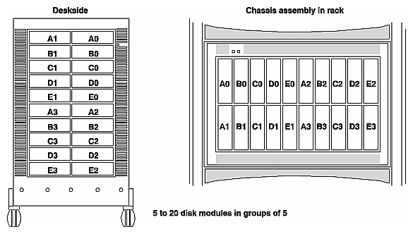
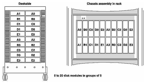
Figure 5-1 diagrams location of disks, which can be replaced by owners or SSEs.
This section describes the precautions that you must take and the general procedures you must follow when removing, installing, and storing FRUs.
The cover(s) and filler panel(s) installed on the Challenge RAID storage system protect the electronic circuits inside the equipment from electrostatic discharge (ESD) damage. However, when you remove these covers and filler panels to replace or install subassemblies, you can inadvertently damage the sensitive electronic circuits in the equipment by simply touching them. Electrostatic charge that has accumulated on your body discharges through the circuits. If the air in the work area is very dry, running a humidifier in the work area will help decrease the risk of ESD damage. You must follow the procedures below to prevent damage to the equipment.
| Caution: Read and understand the following instructions before you remove the cover(s) or panel(s) from the equipment. |
Provide enough room to work on the equipment. Clear the work site of any unnecessary materials or materials that naturally build up electrostatic charge, such as foam packaging, foam cups, cellophane wrappers, and similar materials.
Do not remove replacement or upgrade subassemblies from their antistatic packaging until the exact moment that you are ready to install them.
Gather the tools, manuals, a wrist strap, and all other materials you will need before you remove covers and panels from the equipment. After you remove a cover or panel, avoid moving away from the work site; otherwise, you may build up an electrostatic charge.
Use a wrist strap when handling circuit boards or when touching the electronic circuits inside the equipment.
Replace the cover(s) or panel(s) on the equipment as soon as possible so that the electronic circuits are protected.
When removing or installing a FRU, never use excessive force. If you have difficulty removing or installing a FRU, read the procedures again. Once you have removed a FRU, handle it gently, because a sudden jar or drop could permanently damage it.
The replacement or add–on FRU is shipped in a specially designed shipping container. Store the FRU in this container, and use this container if you need to return the FRU for repair. The storage location of a disk module, SP, power supply module, fan module, or battery backup unit must be maintained within the nonoperating limits specified in Appendix A.
If you have determined that a module has failed by examining the cabinet fault light or by using the raidcli getdisk or raidcli getcrus command, as explained in Chapter 3 in this guide, you can replace the defective module and rebuild your data without powering off the Challenge RAID storage system or interrupting user applications.
| Caution: Removing the wrong drive module can introduce an additional fault that shuts down the physical disk containing the failed module. Before removing a disk module, verify that the suspected module has actually failed. |
The fault indicator on a disk module does not necessarily mean that the drive itself has failed. Failure of a SCSI bus, for example, lights the fault indicator on each disk module on that bus.
| Note: If a disk module in location A0, B0, C0, D0, or E0 fails, caching is disabled until the failed module is replaced. |
To verify a suspected disk module failure, follow these steps:
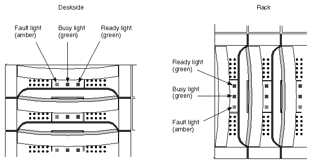
Look for the module with its amber fault light on. Figure 5-2 shows the fault indicator light and other lights on a disk module.
Determine the failed module's ID; see Figure 5-1.
| Caution: Use only Challenge RAID disk modules to replace failed disk modules. Order them from the Silicon Graphics hotline. Challenge RAID disk modules contain proprietary firmware that the storage system requires for correct functioning. Using any other disks, including those from other Silicon Graphics systems, can cause failure of the storage system. |
If you have not already checked the module status with raidcli getdisk, do so now; see Appendix B.
If you have not already checked the unsolicited error log with raidcli getlog for a message about the disk module, as explained in Appendix B, do so now.
A message about the disk module contains its module ID (such as A0 or B3). Check for any other messages that indicate a related failure, such as failure of a SCSI bus or a general shutdown of a chassis, that might mean the disk module itself has not failed.
Note: If you are using storage system caching, the system uses modules A0, B0, C0, D0, and E0 for its cache vault. If one of these modules fails, the storage system dumps its cache image to the remaining modules in the vault; then it writes all dirty (modified) pages to disk and disables caching. The cache status changes, as indicated in the output of the raidcli getcache command. Caching remains disabled until you insert a replacement module and the storage system rebuilds the module into the physical disk unit. For information on caching, see Section 4.12, "Setting Up Caching," in Chapter 4.
| Caution: Although you can remove a disk module without damaging the disk data, do this only when the disk module has actually failed. Never remove a disk module unless absolutely necessary, and only when you have its replacement available. Never replace more than one disk module at a time; use only correct disk modules available from Silicon Graphics, Inc. |
When you change a physical disk configuration, you change the bound configuration of a physical disk unit. Physical disk unit configuration changes when you add or remove a disk module, or physically move one or more disk modules to different slots in the chassis.
| Caution: Unbinding destroys all the data on a physical disk unit. Before unbinding any physical disk unit, make a backup copy of any data on the unit that you want to retain. |
To unbind a disk, use the unbind parameter with the raidcli command. See Section 4.6, "Unbinding Disks," in Chapter 4. Use raidcli bind to configure disks, as explained in Chapter 4.
This section explains
removing the failed disk module
installing a replacement disk module
updating the disk module firmware
| Caution: Use only Challenge RAID disk modules as replacements; only they contain the correct device firmware. For replacement drive marketing codes, see Table 1-2 in Chapter 1. Other disk modules, even those from other Silicon Graphics equipment, will not work. Do not mix disk modules of different capacities within one array. If you replace an unbound disk module, you must update the firmware as explained in Section 5.4.3, "Updating the Disk Module Firmware." |
You can replace a failed disk module while the storage system is powered on. If necessary, you can also replace a disk module that has not failed, such as a module that has reported many "soft" errors. When replacing a module that has not failed, you must do so while the storage system is powered on so that the SP knows the module is being replaced.
| Caution: To maintain proper cooling in the storage system, never remove a disk module until you are ready to install a replacement. Never remove more than one disk module at a time. |
To remove a disk module, follow these steps:
Verify that the suspected module has actually failed.
Caution: If you remove the wrong disk module, you introduce an additional fault that shuts down the physical disk containing the failed module. In this situation, the operating system software cannot access the physical disk until you initialize it again. When a disk fails, the SP automatically unbinds it. To check that the disk has been unbound, use the following raidcli command for the disk module position in question:
raidcli -d device getdisk [diskposition]
If necessary, get the device name first with raidcli getagent. See Appendix B for information on these parameters.
Read Section 5.1, "Handling FRUs," earlier in this chapter.
Locate the disk module that you want to remove; see Figure 5-1 if necessary.
Position the new disk module in its antistatic packaging within reach of the storage system.
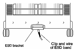
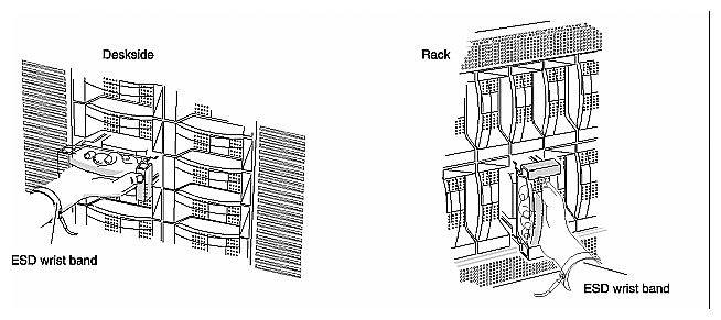
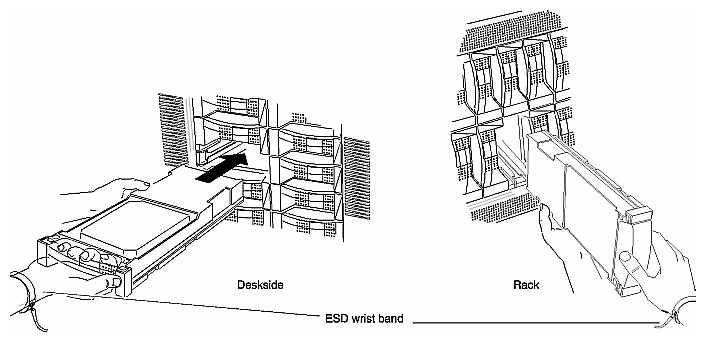
If you are using an ESD wrist strap, attach its clip to the ESD bracket at the bottom of the storage system, as shown in Figure 5-3. Put the wrist band around your wrist with the metal button against your skin.
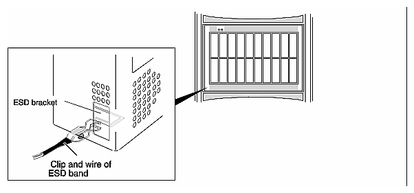
Figure 5-4 shows where to attach the clip on a rack storage system.
Make sure the disk has stopped spinning and the heads have unloaded.
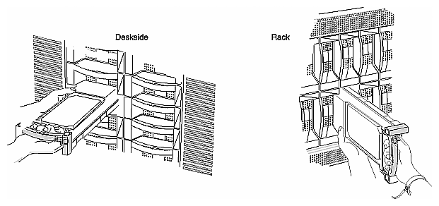
Grasp the disk module by its handle and pull it partway out of the cabinet, as shown in Figure 5-5.
Caution: Never remove more than one disk module at a time. 
Warning: When removing a disk module from an upper chassis assembly in a Challenge RAID rack system, make sure that you adequately balance the weight of the disk module. Supporting the disk module with your free hand, pull it all the way out of the cabinet, as shown in Figure 5-6.
Caution: When removed from the chassis, the disk modules are extremely sensitive to shock and vibration. Even a slight jar can severely damage them. If the ID number for the compartment from which you removed the drive has not been written on the label on the side of the disk module, write it or check the appropriate box; for example, A2.
For the compartment ID numbers, refer to Figure 5-1.
Put the failed disk module in an antistatic bag and store it in a place where it will not be damaged.
Caution: Before installing a replacement module, wait at least 15 seconds after removing the failed module to allow the SP time to recognize that the module has been removed. If you insert the replacement module too soon, the SP may report the replacement module as defective.
To install the replacement disk module, follow these steps:
Touch the new disk module's antistatic packaging to discharge it and the drive module. Remove the new disk module from its packaging.
Caution: The disk module is extremely sensitive to shock and vibration. Even a slight jar can severely damage it. Before installing a replacement module, wait at least 15 seconds after removing the failed module to allow the SP time to recognize that the module has been removed. If you insert the replacement module too soon, the SP may report the replacement module as defective.
Position the disk module in its antistatic packaging within reach of the storage system.
Locate the slot where you will install the disk module; see Figure 5-1.
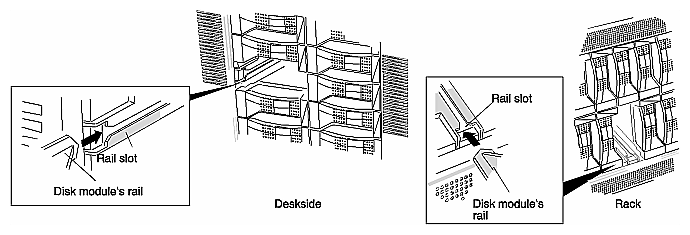
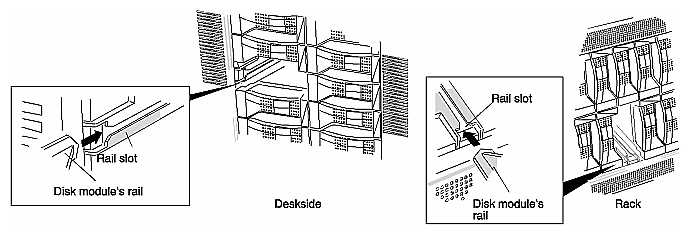
Engage the disk module's rail in the chassis rail slot, as shown in Figure 5-7.
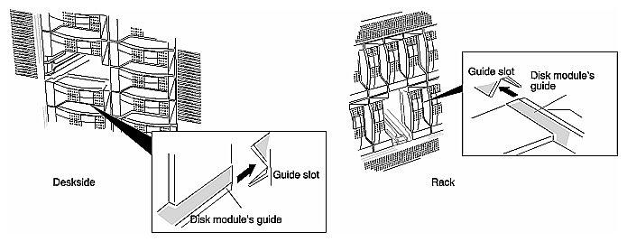
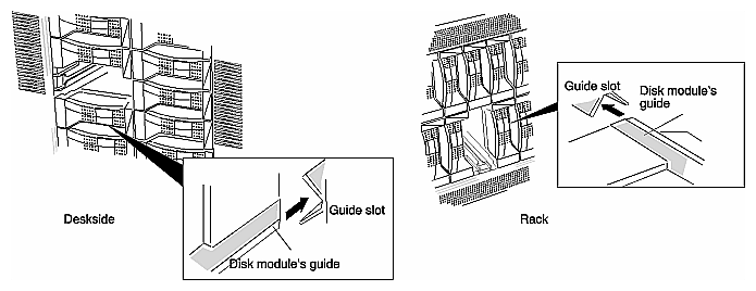
Engage the disk module's guide in the chassis guide slot, as shown in Figure 5-8.
Insert the disk module, as shown in Figure 5-9. Make sure it is completely seated in the slot.
Remove and store the ESD wrist band, if you are using one.
The SP formats and checks the new module, and then begins to reconstruct the data. While rebuilding occurs, you have uninterrupted access to information on the physical disk unit.
The default rebuild period is 4 hours.
| Note: During the rebuild period, performance might degrade slightly, depending on the rebuild time specified and on I/O bus activity. |
For more information on changing the default rebuild period, use raidcli bind, as explained in Appendix B.
After replacing a failed unbound disk module (A0, B0, C0, or A3), update the firmware on the Challenge RAID SP. The firmware (FLARE code) is stored in directories in /usr/raid5/flare:
/usr/raid5/flare/sauna7/flarecode.bin: use this for AMD-based SPs with FLARE code rev. level 7.xx
/usr/raid5/flare/sauna8/flarecode.bin: use this for AMD-based SPs with FLARE code rev. level 8.00 through 8.49
release 2.0 and earlier: /usr/raid5/flare/phoenix8/flarecode.bin: use this for PowerPC-based SPs with FLARE code rev. level 8.50 through 8.99
release 2.1 and later: /usr/raid5/flare/phoenix9/flarecode.bin: use this for PowerPC-based SPs with FLARE code rev. level 9.00 through 9.99
Follow these steps:
Quiesce the bus, disabling all applications. Make sure that only the RAID agent is running.
Enter as root:
raidcli -d device firmware /usr/raid5/flare/directory/flarecode.bin
In this string, the new firmware image /usr/raid5/flare/<directory>/flarecode.bin contains microcode that runs on the SP and also a microcode image destined for the SP PROM, which runs the power-on diagnostics.
You must use this command every time you replace a failed unbound disk module (A0, B0, C0, or A3).
The image in the file given in the command contains microcode that runs on the storage-control processor and possibly also a microcode image destined for the storage-control processor PROM, which runs the power-on diagnostics.
| Note: Once the microcode has been downloaded, each SP in the cabinet reboots. The reboot process takes several minutes, during which time no command-line interface commands are accepted other than getagent. When the code is downloaded, the system reboots the SPs. After the download is complete, stop and restart the agent. |
This command has no output. Use getagent or getsp to return the new firmware version.
Table 5-1 gives marketing codes for add-on disk module arrays. Add-on disk modules are available only in arrays of five.
Table 5-1. Ordering Add-On Disk Module Sets
Unit | Marketing Code |
|---|---|
Add-on five 2 GB drives | P-S-RAID-5X2 |
Add-on five 4.3 GB drives | P-S-RAID-5X4 |
Base array with five 2 GB drives | P-S-RAID-B5X2 |
Base array with five 4 GB drives | P-S-RAID-B5X4 |
Installing an add-on disk module array consists of two procedures:
inserting the new disk module array
creating device nodes and binding the disks
Follow these steps:
| Caution: Never remove more than one disk module or disk filler module at a time. |
Read Section 5.1.1, "Avoiding Electrostatic Discharge (ESD) Damage," earlier in this chapter.
Position the new disk modules in their antistatic packaging within reach of the storage system.
If you are using a wrist band, attach its clip to the ESD bracket on the bottom of the storage system or chassis assembly. Put the wrist band around your wrist with the metal button against your skin.
Locate the slots where you will install the add-on disk modules; consult Figure 5-1 if necessary.
Warning: In a rack, you need not complete each chassis assembly that is partially filled before installing more disk modules in the next chassis assembly. However, avoid making the rack top-heavy. Fill the slots in this order:
Grasp the filler module for the first slot and pull it out of the cabinet; set it aside. If you cannot grasp the module, use a medium-size flat-blade screwdriver to pry it out gently.
Touch the new disk module's antistatic packaging to discharge it and the drive module. Remove the new disk module from its packaging.
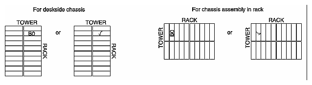
On the label on the side of the disk module, write the ID number for the compartment into which the drive is going. You can either write the slot position on the label in the corresponding place on the matrix or make a check mark in the position to indicate the slot that the disk module occupies. Figure 5-10 shows these two ways of labeling disk module B0.
For reference, Figure 5-11 diagrams all disk module locations.
Engage the disk module's rail in the chassis rail slot, as shown in Figure 5-12.
Caution: Disk modules are extremely sensitive to shock and vibration. Even a slight jar can severely damage them.
Engage the disk module's guide in the chassis guide slot, as shown in Figure 5-13.
Insert the disk module, as shown in Figure 5-13. Make sure it is completely seated in the slot.
Repeat steps 4 through 10 until all add-on modules are installed.
When you are finished installing add-on modules, remove and store the ESD wrist band, if you are using one.
If you are adding disk arrays to a storage system that already has at least one LUN configured, the SPs must be made aware of the new disks. This section explains how to accomplish this without rebooting. Also, in a system with two SPs which are used for primary and secondary paths, both SPs must be made aware of the new disks. Also, the new disks must be bound into LUNs.
Follow these steps:
Change to the /dev directory:
cd /dev
Type
./MAKE_VLUNS controller-numbertarget-number
This command creates the device nodes for the new disks.
Bind the newly installed modules into one or more physical disk units, as described in Section 4.9, "Binding Disks Into RAID Units" in Chapter 4 in this guide.