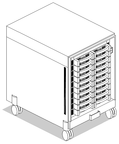
This chapter describes the hardware components that make up the Challenge RAID storage system and the different ways to connect the storage system to a Challenge server. Figure 2-1 is an external view of the deskside version.
 | Note: This guide is written for Silicon Graphics qualified System Support Engineers. Only SSEs should install or replace any components other than disk modules. |
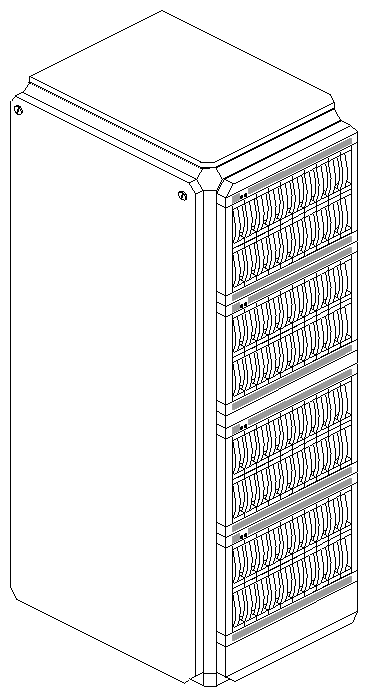
Figure 2-2 is an external view of the Challenge RAID rack, with the maximum of four chassis assemblies installed. Each chassis assembly in a Challenge RAID rack corresponds to one deskside Challenge RAID chassis.
The Challenge RAID storage system consists of a SCSI–2 (small computer system interface 2) interface in the host and a storage-system chassis assembly that contains compartments for these modules:
one or two disk–array storage–control processors (SPs)
five to twenty disk–drive modules in groups of five
one fan module
two or three power supplies (voltage semi–regulated converters)
battery backup unit (optional)
For a Challenge RAID storage system to support storage-system caching, it must have these components:
two SPs, each with 8 or 64 MB of memory
a battery backup unit
disk modules in compartments A0, B0, C0, D0, and E0
Figure 2-3 diagrams the location of the Challenge RAID disks, which can be replaced by the customer or by an SSE.
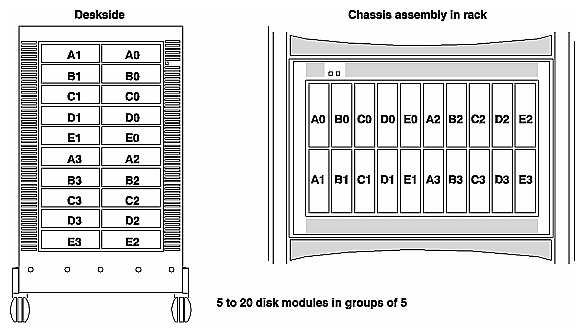
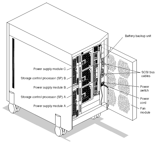
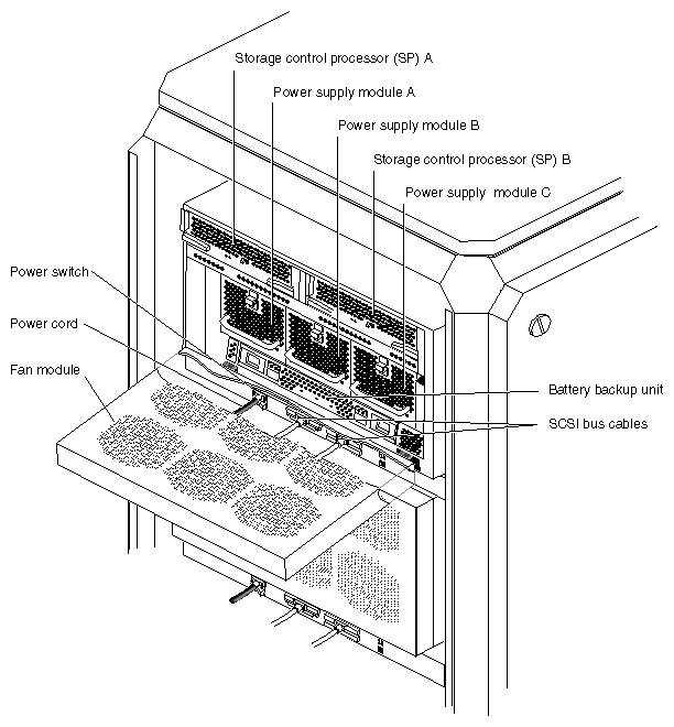
Figure 2-4 shows the Challenge RAID field-replaceable units (FRUs) in the deskside Challenge RAID storage system. Only SSEs replace these.
See Chapter 3 for instructions on opening the storage system.
Figure 2-5 shows the Challenge RAID field-replaceable units (FRUs) in one RAID chassis assembly of a Challenge RAID rack storage system. Only SSEs replace these.
See Chapter 3 for instructions on opening the storage system.
The SCSI–2 interface (or adapter, or controller) is a printed-circuit board that resides in an I/O slot in the Challenge cabinet. It connects to an SP in the storage-system cabinet by a SCSI–2 differential bus, and transfers data between the Challenge memory and the SCSI–2 bus. The interface is included in the Challenge system or can be ordered as a kit.
The storage-control processor consists of a printed-circuit board with two or four memory modules (SIMMs) and a bezel with status lights, and latches to secure the SP in place. The memory modules provide either 8 or 64 MB of SP memory. The SPs are visible when you swing away the fan module from the back of the storage system.
Figure 2-6 shows the AMD®-based SP (Sauna). The PowerPC®-based SP (Phoenix) lacks a power switch, and the SIMM connectors are aligned differently. SIMM connectors on the two types of SP are explained in detail in "Installing or Removing SP Memory Modules (SIMMs)" in Chapter 6.
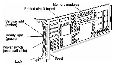
Two status lights indicate the following:
Challenge RAID can support two SPs. Caching requires two SPs, each with the same amount of memory, either 8 or 64 MB. Minimum system memory allowed is 2 MB for Sauna, and 4 MB for Phoenix.
| Note: In storage systems with two SPs, the SPs must be of the same type (Sauna or Phoenix). For caching and failover, the SPs must have the same amount of memory. |
The SP processes data written to or read from the disk modules, and controls the disk modules in the storage system through a synchronous SCSI–2 bus. It has five internal SCSI–2 buses, each supporting as many as four disk modules for a total of 20 disk e modules.
If the Challenge RAID has one SP, you can install a second one while the storage system is running and configure it into the system. When both SPs are installed and configured, you can replace either SP while the storage system is running.
| Note: Never attempt to replace any SP components except memory modules (SIMMs). |
A disk–drive module, also called a disk module, consists of a disk drive, a power regulator board, internal cabling, and a plastic carrier. The carrier has a handle and guides for inserting and holding the module in the storage system's chassis. A label attached to the carrier's top shows the drive module's model number and capacity. Figure 2-7 shows a disk-drive module.
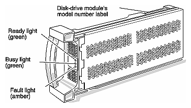
Three status lights on the module indicate the following:
ready light (green): lights while the disk–drive module is powered up and ready for use
busy light (green): lights while the drive is in use; for example, during formatting or user I/O operations
fault light (amber): lights when the module is shut down by the SP because the module failed; also lights after you replace the drive, while the replacement drive spins up to speed
 | Caution: Use only Challenge RAID disk modules to replace failed disk modules. Challenge RAID disk modules contain proprietary firmware that the storage system requires for correct functioning. Using any other disks, including those from other Silicon Graphics systems, can cause failure of the storage system. |
You can remove or install any one module within an array group while the storage system is running.
| Note: Never open a disk–drive module or attempt to replace any of its internal components. Never remove more than one disk module or filler module at a time. Always use ESD precautions when handling disk modules. |
The power supply modules, or voltage semi-regulated converters (VSCs) convert the installation site's AC line voltage to the 48, 24, and 18 VDC required to power the modules in the storage--system chassis. A storage system normally contains two power supply modules. Three power supply modules provide high-availability operation and might be required for certain Challenge RAID configurations.
The power supplies are visible when you swing open the fan module on the back of the storage system. Figure 2-8 shows a power supply module.
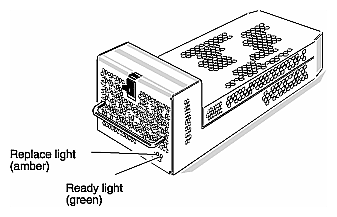
Two status lights on the power supply module indicate the following:
You can remove or install a power supply while the storage system is running; however, a minimum of two or three power supply modules is required, depending on the configuration.
| Note: Never open a power supply module or attempt to replace any of its internal components. |
If a power supply module fails, replace it as quickly as possible. If the customer has only two power supply modules and one of them fails, the storage system shuts down. If the customer has three power supplies and one of them fails, the storage system continues to operate, but the failed power supply module should be replaced as soon as possible to restore high–availability operation. Failure to replace the power supply module could cause the storage system to shut down if either the fan module or another power supply module were to fail.
Challenge RAID uses a single fan module, also called a fan pack, that attaches to the back of the storage system's chassis. The fan module contains six high-capacity, multiple-speed fans and a control/monitor board. Figure 2-9 shows the fan module.
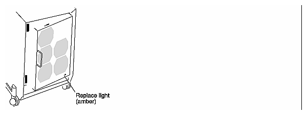
The amber status light (replace light) comes on when a fan in the module is not working.
For high-performance operation, if a fan stops working, the remaining five fans speed up to maintain air flow, and the replace light turns on to indicate that you must replace the fan module as soon as possible. If one of the fans in the module fails, replace the fan module as quickly as possible to maintain high-performance operation. Failure to replace the module could cause the Challenge RAID storage system to shut down if either a power supply module or another fan fails.
You can remove a fan module while the storage system is running. The fan module is mounted on hinges so you can swing it away from the storage system. A mechanical lock and magnetic catches hold the fan module closed. If the fan module remains open for more than about two minutes, the storage system automatically shuts down to prevent overheating.
| Note: Never open the module or attempt to replace any of its internal components unless you are specifically trained on this unit. |
The battery backup unit is required for the Challenge RAID cache. In the event of a power outage, the battery backup unit allows the SP to shut down the storage system in an orderly way. The battery backup unit can provide up to 60 seconds of power, which gives the SP enough time to empty its cache by writing data from the cache to the physical disk units.
To conserve power, the SP shuts down all unnecessary disk modules while emptying the cache. Once cache data is safely stored on the physical disk units, the SP disables the battery backup unit to preserve the life of its internal power cells. When power returns, the battery backup unit recharges its cells automatically.
The battery backup unit is visible when you swing open the fan module on the back of the storage system. Figure 2-10 shows the battery backup unit.
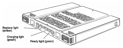
Three status lights indicate the following:
ready light (green): lights when the battery backup unit is fully charged and ready to handle a power outage, and has been enabled by a SP; blinks when the battery backup unit is supplying power during an outage
charging light (green): lights while the battery backup unit is recharging its internal power cells or when the battery backup unit has been disabled by a SP
replace light (amber): lights when the battery backup unit's self diagnostics determines that the battery backup unit has failed, and momentarily when the battery backup unit powers on
You can install or remove a battery backup unit while the disk-array storage system is running.
| Note: Never open a battery backup unit or attempt to replace any of its internal components. |
A Challenge RAID storage system connects to one or two Challenge servers by a wide SCSI–2 differential bus to a SCSI–2 interface. It can use one or two SCSI buses. Four configurations are available:
basic
dual-interface/dual-processor
split-bus
dual-bus/dual-initiator
This section lists the basic components of each configuration and shows their interconnections.
For a storage system to support storage–system caching, it must have
two SPs, each with 8 or 64 MB of memory
a battery backup unit
disk modules in compartments A0, B0, C0, D0, and E0
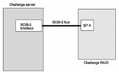
Components of the basic configuration are
Challenge server with one SCSI–2 interface
one SCSI–2 bus
Challenge RAID storage system with one storage-control processor (SP A)
Figure 2-11 diagrams the basic configuration.
Components of the dual-interface/dual-processor configuration are
Challenge server with two SCSI–2 interfaces
two SCSI–2 buses
Challenge RAID with two storage-control processors (SP A and SP B)
Figure 2-12 diagrams this configuration.
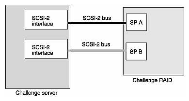
In this example, if one SP or SCSI-2 interface fails, stored data can be accessed through the alternate path. If the customer uses XLV volumes and applicable patches, this configuration provides simple alternate path switching (failover).
| Note: After you replace the failed SP or SCSI-2 interface, you must reassign LUN ownership, as explained in "Reassigning LUN Ownership" in Appendix C. |
Components of the split-bus configuration are
two Challenge servers, each with one SCSI–2 interface
two SCSI–2 buses (one per Challenge server)
Challenge RAID with two SPs
Figure 2-13 diagrams this configuration.
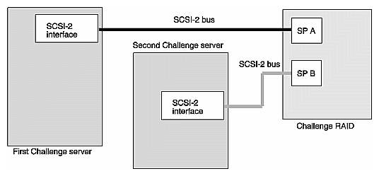
In this configuration, if SP A fails, SP B takes over ownership of SP A's LUNs if auto-assign is enabled (which it is by default). After you replace SP A, you must use the trespass command to transfer ownership of SP A's LUNs back to the new SP A. "Reassigning LUN Ownership" in Appendix C in this guide gives instructions.
Components of the dual-bus/dual-initiator configuration are
The dual-bus/dual-initiator configuration provides the highest availability. Each host has two SCSI-2 adapters, each of which connects by a separate SCSI-2 bus to a separate SP in the storage system. Since this configuration protects against a SCSI-bus cable failure, it provides higher availability than the dual-initiator configuration. It is for enterprises requiring the highest level of availability, such as the Oracle Parallel Server™ and IRIS FailSafe™ products. Note that specific software is included in these products that protects the integrity of the data.
For better performance with this configuration, some physical disk units are bound on one SP and the other physical disk units on the other SP. The SP that binds a physical disk unit is the default owner of that physical disk unit. The route through the SP that owns a physical disk unit is the primary route to the physical disk unit. The route through the other SP is the secondary route to the physical disk unit, and is available if a component in the primary route fails. Figure 2-14 diagrams this configuration.
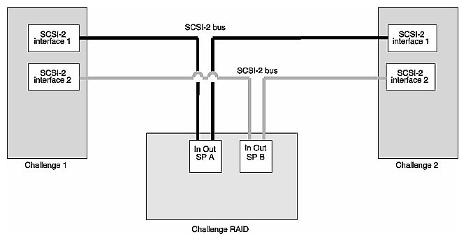
| Caution: Because both hosts can access all disks in this configuration, specific software is required to protect the integrity of the data, which is not included in the Challenge RAID storage-system software. The OPS and IRIS FailSafe products include such software. |
| Note: To work reliably, this configuration requires SCIP mezzanine boards. |