This manual introduces the Everest rackmount graphics and server systems (Model CMNA010) and provides the information necessary to install, configure, and test them. The information contained here is intended for Silicon Graphics® system support engineers (SSEs) or Silicon Graphics-trained personnel only.
This revision of the CHALLENGE[tm]/Onyx[tm] XL Rackmount Installation Instructions includes the new AC power requirements, updated System Controller messages, as well as the optional Cardcage 3 installation and configuration instructions.
The Everest rack-mounted server system is sold as the CHALLENGE[tm] XL Rackmount and the graphics system is sold as the Onyx[tm] XL Rackmount. Both configurations consist of an Everest system board set mounted in a 19-inch rack chassis. Graphics machines include VTX[tm] and RealityEngine2[tm] board sets. A SCSI drive enclosure, capable of supporting eight half-height or four full-height drives, is also part of the standard configuration.
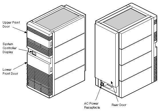
The rackmount chassis evolved from the POWER Center[tm] systems. The physical dimensions of the chassis are virtually identical to the POWER Center, except that the Everest chassis is 6 inches deeper. External views of the Everest rackmount chassis are shown in Figure I-1.
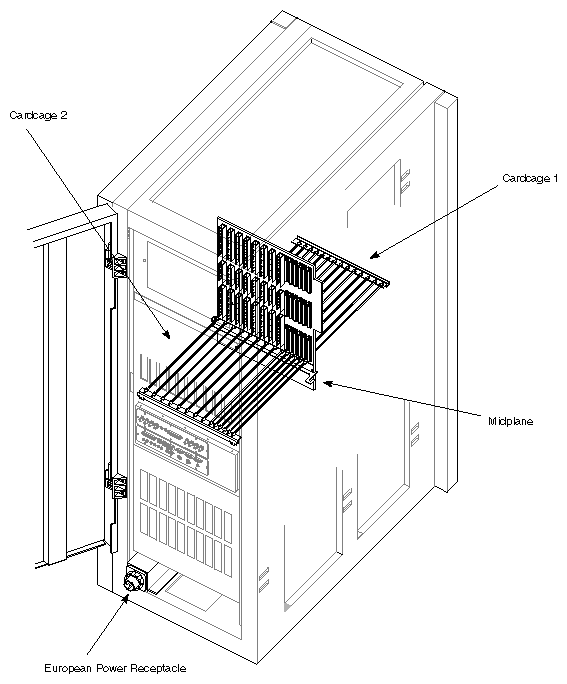
The most important departure from previous system chassis is the midplane. The midplane is a backplane that has connectors mounted on both sides. It is located in approximately the center of the chassis and supports both a front and a rear cardcage (see Figure I-2).
Another feature not seen on earlier systems is the System Controller. This component monitors the status of the system using an array of sensors as well as a direct serial link to the master CPU board. If the sensors indicate a problem, the System Controller can shut down the system without any input from the CPU.
The third important departure from previous chassis is the power distribution scheme. Referred to internally as "pay--as-you-go," the Everest power subsystem uses from one to three modular off-line switchers (OLS) to convert the AC line power to the appropriate backplane voltage. A variety of power boards (DC-to-DC converters) are installed in the cardcages to convert the backplane voltage to voltages suitable for the boards and drives. The power boards vary in the voltages they supply and in the amperage available for a given voltage. As system power requirements change, the power boards can be added or removed from the system.
Chapter 1, "Chassis Tour," identifies the physical location and function of each of the Everest system components. Functional descriptions of both board sets are provided in Chapter 2, "Theory of Operations," Steps to installing a rackmount system are provided in Chapter 3, "Installation."