Do the following for each virtual library in turn:
 | Note: The example output for some commands shown here has been edited
for length and readability.
The example screen shots are taken using the 4.5 version of the VTL GUI. Important differences with the 7.5 version of the VTL GUI are noted. |
This section discusses the following:
The very first time you access the VTL Console, you must add the VTL Server. Do the following:
Start the VTL Console according to the directions in your SGI 400 VTL system administrator's guide.
Add the VTL server and log in to the VTL Console:
Right-click the COPAN nnn Servers entry in the left-hand tree and select Add, as shown in Figure 3-1.
Enter the following in the dialog box:
The name of the VTL server (such as VTL0) or its IP address
The user name root
The password CPN200t
Click OK.

You can then proceed to “Determine the Migration Tape Size for the Library”.
After the initial log in, you can connect to the VTL Console via the VTL server. Do the following:
Start the VTL Console according to the directions in your SGI 400 VTL system administrator's guide.
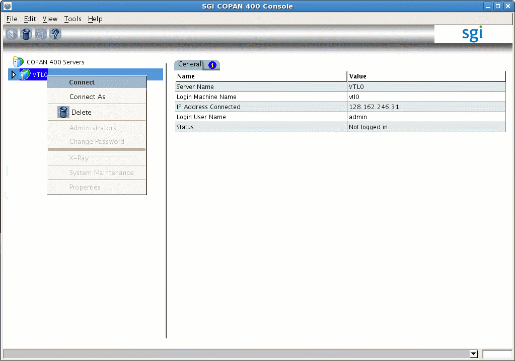
Right-click the VTL server name, such as VTL0, in the left-hand tree and select Connect , as shown in in Figure 3-2.
Enter the user name and password.
Click OK.
You can then proceed to “Determine the Migration Tape Size for the Library”.
SGI 400 VTL shelves use redundant array of idle disks (RAID) technology. There are up to eight shelves, and each shelf has a RAID controller and 26 groups of disks. Each group of disks is referred to as a RAID set. Each RAID set is configured to hold a fixed number of virtual tapes, all of which are the same size. You must specify the size of the virtual tapes.
| Note: It is possible for different shelves in the same COPAN cabinet to contain RAID sets with different capacities, so each shelf could have a different optimal virtual tape size. |
You should select the number of migration tapes and the tape size that best accommodate the way you want to use DMF and that will best fit into the usable space on the RAID set. (A certain percentage of space on the RAID is required for overhead. A greater number of tapes requires a larger amount of overhead.)
By default, the Console creates virtual tapes that are the same size as the corresponding physical tapes that are being emulated; because a virtual tape cannot span RAID sets, this can end up wasting otherwise usable RAID space. For example, a RAID set with 1,433 GB of usable space could accommodate only one 768-GB tape, wasting RAID space. Therefore, you want to select a different tape size if you are not obligated to match the physical size. You should choose a number of virtual tapes and a virtual tape size that wastes as little space as possible.
| Note: If you want a huge number of tapes (more than the default slot number of 678), including both migration tapes and dump tapes, see Appendix A, “Using an Extremely Large Number of Tapes”. |
Use the left-hand tree to access the Fibre Channel devices for the shelf you want to configure, such as the following for shelf 0:
VTL0 -> Physical Resources -> Storage Devices -> Fibre Channel Devices -> Shelf 0
Record the number that appears in the right panel under the column header Size (MB) (such as the number 1,430,414 shown in Figure 3-3). This is the total size of the RAID set.
Table 3-1 and Table 3-2 show suggested tape sizes for common sizes of RAID sets.
Table 3-1. Suggested Tape Sizes for Common RAID-Set Sizes (4.5 VTL)
RAID Unit Size (MB)
Number of Tapes Per RAID Unit
Virtual Tape Size (GB)
715,229
1
698
715,229
2
349
1,430,414
2
698
1,430,414
3
465
1,430,414
4
349
Table 3-2. Suggested Tape Sizes for Common RAID-Set Sizes (7.5 VTL)
RAID Unit Size (MB)
Number of Tapes Per RAID Unit
Virtual Tape Size (GB)
8,582,968
1
8,376
8,582,968
2
4,188
8,582,968
3
2,792
8,582,968
4
2,094
If you have a RAID-set size listed in one of the above tables, record the value for use later (in step 7b of “Create the Library”). Otherwise, go on to step 3 to determine the tape size for the library.
Multiply the total size of the RAID set by .976 to get the approximate amount of usable space. You can then divide that result by the desired number of tapes to see what each corresponding virtual tape size is; choose the size that will give you the number of tapes you prefer that wastes the least amount of space.
In general, a larger number of smaller-sized virtual tapes will result in fewer partially-full tapes in the DMF database (and therefore more room for new data). This can potentially provide faster recalls of migrated data because there are more tapes available for reading (you cannot simultaneously write to and read from the same tape). However, you do not want to use tapes that are unreasonably small, as that might cause excessive mounts and unmounts. Typically, you want to use a migration tape that is at least 500 GB.
Use the following formula as a guideline:
(Total_RAID_Set_Size * .976) / #_Migration_Tapes = Migration_Tape_Size
For example, if your total RAID size is 1,430,414 MB and you want two tapes, the resulting virtual tape size would be approximately 698,042.032 MB (or 698 GB).
(1430414 MB * .976) / 2 = 698042.032 MB (or 698 GB)
Record this information for use later (in step 7b of “Create the Library”).

Do the following:
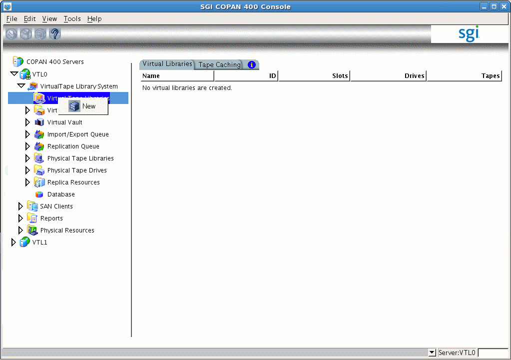
Open the left-hand tree and place the cursor over Virtual Tape Libraries, such as the following for VTL0:
VTL0 -> Virtual Tape Library System -> Virtual Tape Libraries
Right-click and select New as shown in Figure 3-4.
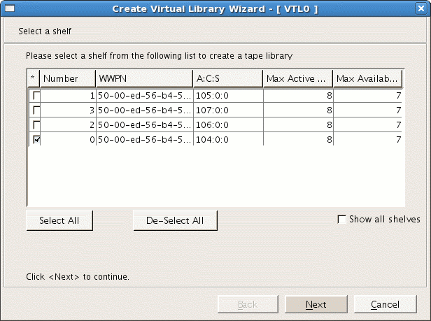
Select a shelf by clicking the check box. Begin with shelf number 0, as shown in Figure 3-5.
Note: In the 7.5 VTL GUI, the values for maximum active LUNs and maximum available drives are both 15. Take note of the Max Available drives (for use later in step 4c) and click Next.
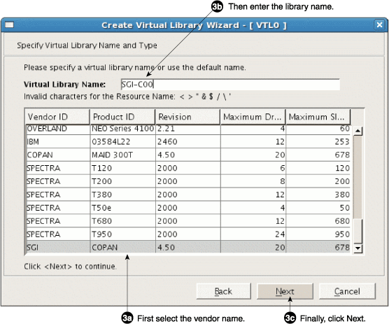
Select the vendor ID type and then name the virtual library in that order, as shown in Figure 3-6.
Note: If you name the library first and then select the vendor ID type, the library name will be replaced by the default name. For simplicity during operation, SGI recommends that you do not use the default name but instead manually enter a name that corresponds to the shelf number. Select SGI under Vendor ID.
Change the library name in the Virtual Library Name field so that it corresponds to the SGI 400 VTL shelf number, such as SGI-C00 for shelf 0, SGI-C01 for shelf 1, and so on.
Click Next.
Enter the virtual drive information:
Use the resulting default name in the Virtual Drive Prefix field.
Specify the Max Available value noted above in step 2 (rather than use the default) for Total Virtual Drives.
Note: The example procedure presented in this guide uses the value 7, as shown in Figure 3-7. The maximum available drives is 50% of the total number of drives. When using the version 7.5 software, the maximum available drives is 15. You must adjust this procedure and the contents of the DMF configuration file appropriately for your system. Click Next.
Do not make any changes on the next set of screens:
Do not check the Enable Automated Tape Caching box; just click Next.
Do not check the Auto Archive / Replication box or make any changes on the virtual library information screen; just click Next.
(7.5 VTL GUI only) Do not check the Enable Tape Duplication box.
Enter the remaining virtual library information:
Enter the barcode start and end numbers for the shelf, using the following required naming scheme:
Start: CCS9AA
End: CCS9ZZ
where:
CC uniquely identifies a cabinet at your site. This guide uses C0 for (“cabinet 0”). You may use a different naming convention if you prefer, using the characters [0-9A-Z][0-9A-Z ].
S represents the shelf position in the cabinet. There are up to eight shelves in an SGI 400 VTL cabinet, shelf 0 (bottom) through shelf 7 (top).
9AA and 9ZZ are required values.
Note: The naming convention allows a script to relabel the barcode (also known as the volume serial number, VSN) so that it indicates the specific RAID set in which the tape is stored. This in turn allows DMF to optimize I/O to and from the shelf.
For example, for the virtual library on cabinet 0 and shelf 0 (therefore SGI-C00), you would enter the following barcode information, as shown in Figure 3-8:
C009AA
C009ZZ
For the virtual library on the next shelf (cabinet 0 and shelf 1, therefore SGI-C01), you would enter the following barcode information:
C019AA
C019ZZ
Note: Verify that you have used the correct shelf number. Use the defaults for Number of Slots and Import|Export Slots.
Note: If you must increase the number of slots, see Appendix A, “Using an Extremely Large Number of Tapes”.
Click Next.
Enter the virtual tape properties:
(4.5 VTL GUI only) Do not select Tape Capacity on Demand.
Enter the Maximum Capacity tape value from “Determine the Migration Tape Size for the Library”.
Click Next.
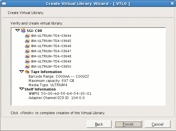
Verify that the library information displayed matches what you intended to configure and click Finish to complete creation of the library, as shown in Figure 3-9.
Click Yes to create the virtual tapes and go to the next section, “Configure Virtual Migration Tapes for the Library”.


| Note: If your site's data would benefit from software compression, you can enable SGI 400 VTL compression mode (and therefore DMF compression) for each application server (VTL0 and VTL1 ). See Appendix B, “Enabling Compression ”. However, if you are using the 4.5 VTL software, compression carries an overhead CPU penalty and is not appropriate in some cases. |
This section discusses the following steps:
| Note: This can be a time-consuming process. |
Do the following to create migration tapes for the library:
Select the default Express method for creating tapes and click Next.
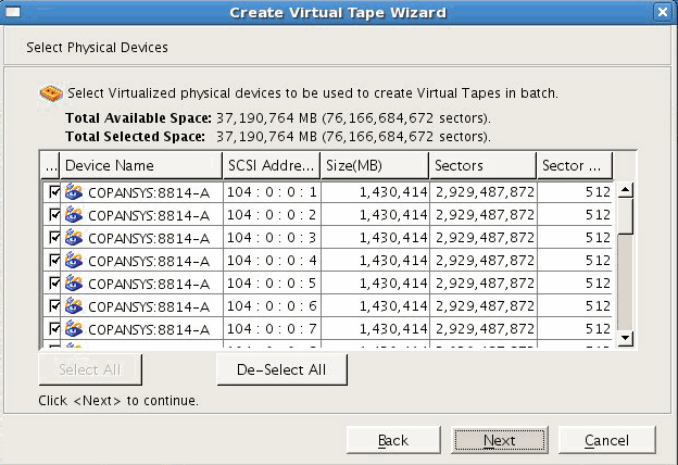
Click Next to accept all of the physical devices (selected by default), as shown in Figure 3-10.
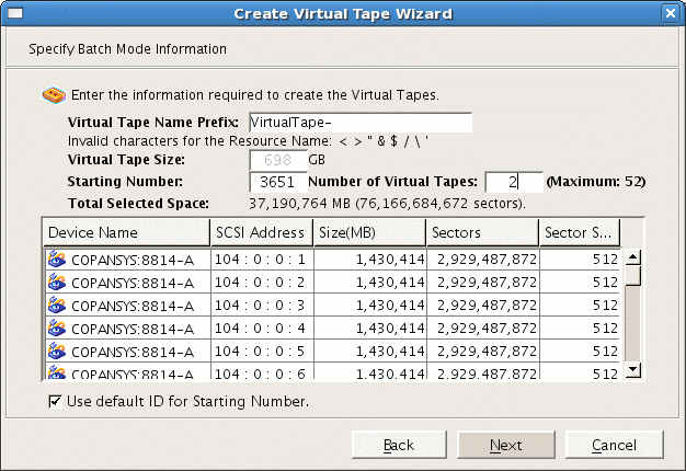
Enter in the number of tapes to be configured and click Next, as shown in Figure 3-11.
Note: This step is creating the actual logical tape volumes on the RAID, which will require that disks be spun up; the more tapes you create, the more time will be required. With the 7.5 VTL GUI, you can create all of the tapes in one batch at a convenient time. However, if you are using the 4.5 VTL GUI, you cannot enter a number greater than 50. For example, if there are 52 tapes to be configured, you must do them in two groups (such as 2 and 50) by repeating some of these steps. Do not change the Barcode Starts information (originally input in step 6a of “Create the Library”) because the Console will continue from the correct point. Do not click Use the following barcode range for this batch.
Click Next to select the defaults for the barcode range option.
Verify the tapes to be created and select Finish to create the first group of tapes for this library, as shown in Figure 3-12.
Note: The more tapes created, the longer this step will take. For example, depending upon the disk and power configuration, creating 50 tapes can take more than 15 minutes (during which time there will be no updates displayed). Click OK to complete the step.
Open the left-hand tree and place the cursor over Tapes, such as the following for library SGI-C00:
VTL0 -> Virtual Tape Library System -> Virtual Tape Libraries -> SGI-C00 -> Tapes
Right-click and select New Tape(s).
Repeat steps 1 through 7 above to create the remaining tapes for this library. (For example, if there are 52 total tapes possible and you entered 2 previously for step 3, enter 50 this time.) The more tapes created, the longer the Finish step will take.

The DMF library server uses the barcode when selecting tapes. You must run a script to relabel each virtual tape's barcode so that it indicates the specific RAID set in which the tape is stored, in order to optimize I/O to and from the shelf. (For example, C009AA might be transformed into C00AAA, where the fourth character identifies the RAID set to DMF.)
Do the following:
Ensure that there is no other activity on the Console or on the VTL application server that controls the library you have just created (such as VTL0 for library SGI-C00). This is a requirement for the duration of this procedure.
Run the dmreadycopantapes script on the VTL application server from the /usr/local/dmf directory.
Note: This step requires that you previously downloaded the required files from the DMF server to each VTL application server, as specified in “Copy the Support Files to the VTL Application Servers” in Chapter 1. The script will output an executed successfully line for each barcode that is changed. Depending upon the number of tapes and drives, this can be a time-consuming process. For example:
4.5 VTL software:
[root@VTL0 vtl]# cd /usr/local/dmf
[root@VTL0 dmf]# ./dmreadycopantapes

Command: settapeproperty executed successfully.
...
Command: settapeproperty executed successfully.
[root@VTL0 dmf]#
7.5 VTL software:
[root@VTL0 vtl]# cd /usr/local/dmf
[root@VTL0 dmf]# ./dmreadycopantapes

/usr/local/sgi/vtl/bin/iscli settapeproperty --server-name=127.0.0.1 --vdevid=10000121 --barcode=C00AAZ --force
...
/usr/local/sgi/vtl/bin/iscli settapeproperty --server-name=127.0.0.1 --vdevid=10000172 --barcode=C00ZCE --force
[root@VTL0 dmf]#
For more information, add the -v option.

Caution: The script must complete successfully in order for DMF to function properly. If there are errors, fix them before continuing. If necessary, contact SGI Support.
In this step, you will free disk space from only one library ( SGI-C00) so that the space can later be reclaimed for the purpose of dump tapes (which will occur in Chapter 4, “Configure Virtual Dump Tapes”.) The dump tapes must be on one library only. To avoid problems in case of potential hardware failure, the dump tapes should be spread across the RAID sets on the shelf. To make the best use of disk space, the dump tapes should be sized to fit the amount of data needed to accommodate all of the dumps for a day's full backup.
| Note: If the dumps for a day's backup require more than one tape, it will increase the complexity and time requirements of restores. |
Do the following:
Determine how many migration tapes must be deleted in order to free up the required amount of dump space per day that you established in “Determine the Backup Requirements For Your Site” in Chapter 1. Do the following:
Divide the migration tape size (determined in “Determine the Migration Tape Size for the Library”) by the dump space needed per day (estimated in “Space Required for the Daily Backup” in Chapter 1) to determine the number of dump tapes that you can create from the space occupied by one migration tape:
Migration_Tape_Size / Dump_Space_Needed_Per_Day = #_Dump_Tapes_Per_Migration_Tape
For example, suppose you determined that your migration tape size is 698 GB and you estimated that you require 100 GB for each day's dump set. You can therefore make six dump tapes out of each migration tape:
698 / 100 = 6.98 (rounds down to 6 dump tapes per migration tape)
Note: This means that there are 98 GB of unused space that are left on the RAID set. In step 2 below, you will make use of this space in the final tape size. Divide the total number of dump tapes required (established in “Number of Dump Tapes Required” in Chapter 1) by the number of dump tapes per migration tape to determine the number of migration tapes to be deleted:
#_Dump_Tapes / #_Dump_Tapes_Per_Migration_Tape = #_Migration_Tapes_To_Be_Deleted
For example, using the default DMF configuration file for SGI 400 VTL, you will retain the dumps for 28 days (requiring a minimum of 29 tapes). Because you can make 6 dump tapes out of each migration tape, you therefore need to delete 5 migration tapes:
29 / 6 = 4.83 (rounds up to 5 migration tapes to be deleted)
Because you must delete 5 migration tapes and you can get 6 dump tapes per migration tape, you will end up with a total of 30 dump tapes, which is 1 greater than the absolute minimum of 29; having an extra dump tape is a good precaution.
Determine the size of the dump tape so that it includes the space that was left over after the calculation you made in step 1a above. To do this, divide the amount of space left over in the calculation of the number of dump tapes in step 1a above (in this case, 98 GB) by the number of dump tapes created per migration tape and add it to the original dump space needed per day. This will determine the final dump tape size:
Total_Left_Over  /  #_Dump_Tapes_Per_Migration_Tape  =  Left_Over_Per_Dump_Tape

Left_Over_Per_Dump_Tape  +  Dump_Space_Needed_Per_Day  =  Dump_Tape_Size
For example:
98 / 6 = 16.333333 (rounds down to 16)

16 + 100 = 116
Take note of the Dump_Tape_Size value for use later as the Maximum Capacity field in step 2 of “Create the Dump Tapes” in Chapter 4.
Note: It is possible to later reclaim more space for dump tapes, as long as there is still space on the shelf. However, it is more complicated. See Appendix C, “Reclaiming Space for Dumps”. Delete the required number of migration tapes individually, selecting tapes across the RAID set by chosing tapes with barcodes that have different letters of the alphabet for the fourth character (the fourth character specifies the RAID set). Doing so will reduce the risk due to possible hardware failures.
For example, if you wanted to delete 5 migration tapes, you might choose to delete the following (highlighting the fourth character):
C00AAA
C00DAD
C00GAG
C00JAJ
C00MAM
   ^
To delete a given tape, do the following:
To delete tapes with the 4.5 VTL GUI, do the following:
Open the left-hand tree and place the cursor over the library name, such as the following for library SGI-C00:
VTL0 -> Virtual Tape Library System -> Virtual Tape Libraries -> SGI-C00
Right-click and select Delete Tape(s) .
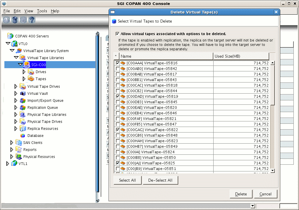
Click the boxes for the tapes you want to delete and click Delete, as show in Figure 3-13.
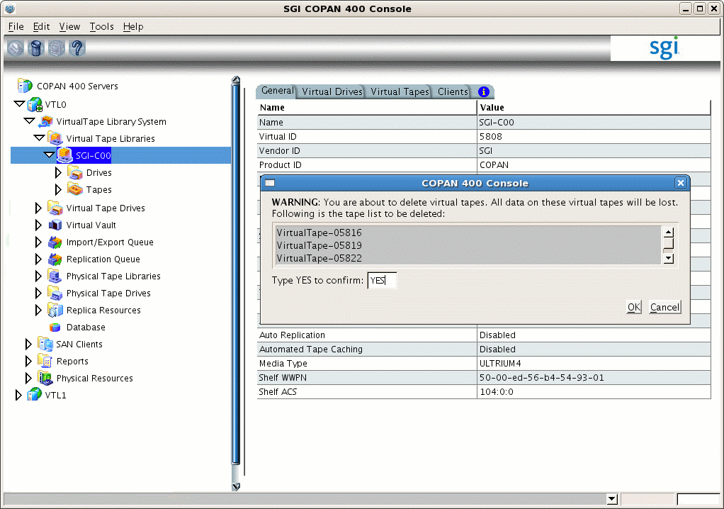
In the WARNING dialog, type YES to confirm that you want to delete the tapes and click OK, as shown in Figure 3-14. (There is no data on the tapes at this point, so it is safe to delete them.)
To delete tapes with the 7.5 VTL GUI, do the following:
Open the left-hand tree tapes display for the library, such as the following for library SGI-C00:
VTL0 -> Virtual Tape Library System -> Virtual Tape Libraries -> SGI-C00 -> Tapes
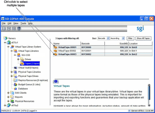
In the right-hand panel, click the names of the tapes that you want to delete. Use Ctrl+click to select multiple tapes or Ctrl+Shift+click to select multiple tapes in sequence. For example, Figure 3-15 shows two tapes that are highlighted.
Right-click and select Delete Tapes in the pop-up window.
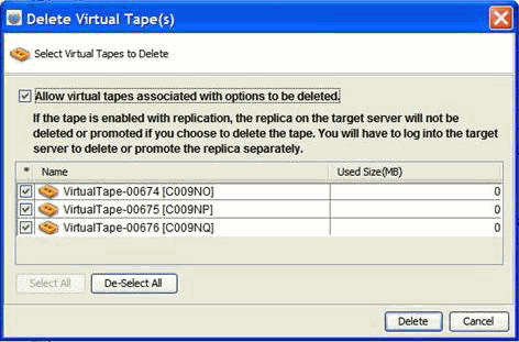
Verify that the correct tapes are selected. For example, Figure 3-16 shows that three tapes are selected for deletion.
Click Delete.
This section exports SGI 400 VTL access to a particular DMF server port via a particular SGI 400 VTL server port using world wide port names (WWPNs). To export library access, you must do the following:
Identify the ports you want to connect on the DMF server (which uses the initiator WWPN) and on the SGI 400 VTL server (which uses the target WWPN). There are four ports available for each VTL server (vtl0 and vtl1); the number of ports available on the DMF server will vary by site.
Configure a target WWPN on the SGI 400 VTL shelf (such as shelf 0) to connect the pair of desired ports. This target WWPN is internal to the SGI 400 VTL cabinet and is similar to a switch's zone.
| Note: For optimum bandwidth, SGI recommends that you configure each shelf target WWPN to a unique pair of ports. Ideally, each target WWPN on the VTL server should connect to a different initiator WWPN on the DMF server. However, if this is impossible due to insufficient ports on the DMF server, you should configure each shelf individually through a unique target WWPN (rather than configuring multiple shelves on a single target WWPN) in order to use unique initiator/target pairs. |
The SGI 400 VTL cabinet has a built-in zoning capability that lets you control which host ports in the SAN can see which virtual libraries. By default, the libraries are not visible anywhere; you must use the steps in this section to configure each library to accept Fibre Channel commands from only the particular port on the particular host that will be running OpenVault, thereby preventing all other initiator WWPNs from causing problems. Essentially, you are creating a Fibre Channel zone where the only members in the zone are the OpenVault host bus adapter (HBA) and the virtual library.
Do the following:
Log in to the DMF server and display the WWPN of the DMF server port that you want to connect to the SGI 400 VTL shelf for this library. To do this, view the contents of the appropriate port_name file:
dmfserver# cat /sys/class/fc_host/port/port_name
In this case, suppose you connected DMF server burn on port host5 to shelf 0 (library SGI-C00 ). To determine the WWPN of host5, view the contents of its port_name file. For example:
burn# cat /sys/class/fc_host/host5/port_name
0x210100e08b3c337d
You will use the WWPN (in this case, 210100e08b3c337d) later in step 5.
In the left-hand panel of the Console, right-click SAN Clients and select Add.
Enter the name of the DMF server in the Client Name field, click Find, then click Next.
Note: If the client WWPN is in a zone, the Console will automatically let you select initiators only from that zone and will skip this step. Select Fibre Channel and click Next.
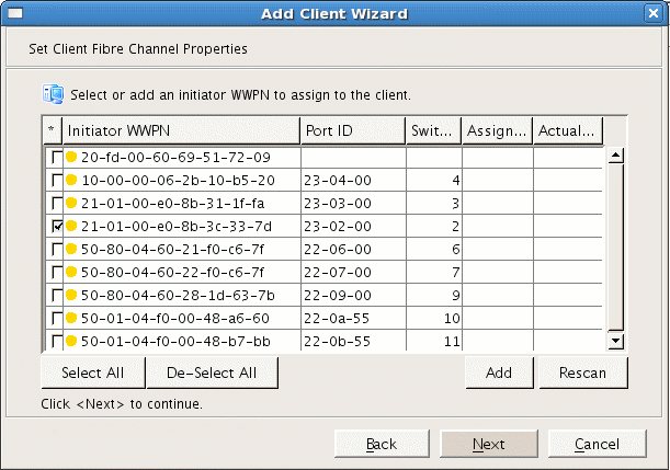
Select the initiator WWPN that corresponds to the WWPN of the DMF server port that you displayed in step 1 above.
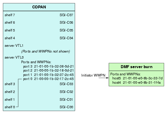
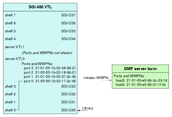
Note: If there is only one initiator WWPN in the client, the Console will automatically select it for you and this dialog will not be displayed. For example, step 1 displayed 210100e08b3c337d, so you would check that initiator WWPN line in the Console and click Next, as shown in Figure 3-17. Figure 3-18 shows the relationship of the Initiator WWPN field to the DMF server port.
Do not check the boxes for Enable Volume Set Addressing or Enable Celerra Support ; just click Next.
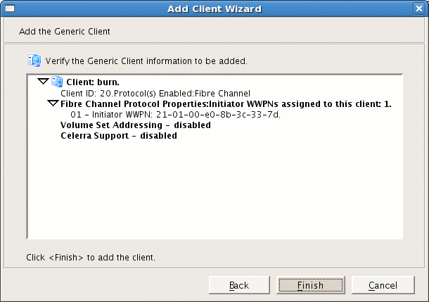
Verify that the client name and initiator WWPN information are as you intended and click Finish. Figure 3-19 shows an example.
Note: The 7.5 VTL GUI also displays the following: IBM System i Support -- disabled
In the left-hand panel of the Console, place the cursor over the name of the DMF server under SAN Clients . For example, for DMF server burn:
VTL0 -> SAN Clients -> burn
Right-click and select Assign.
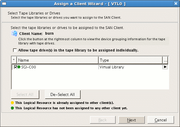
Select the library name, such as SGI-C00 for library 0 on shelf 0. (The green dot indicates that the resource is available and has not been assigned to a client.) Click Next. Figure 3-20 shows an example for SGI-C00. Figure 3-21 shows the relationship of the Name field to the SGI 400 VTL.
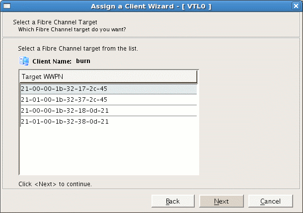
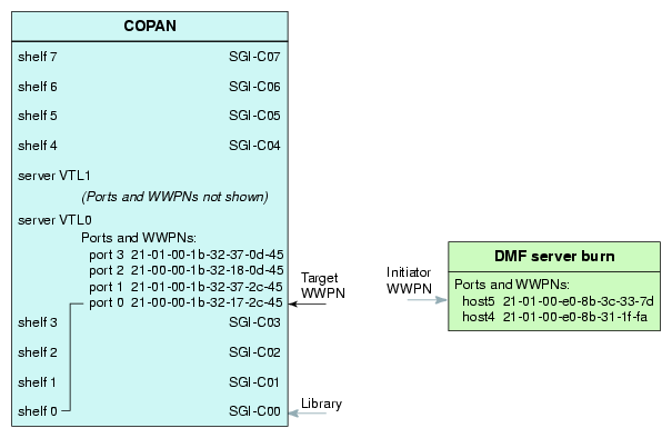
Select a target WWPN that will be used to connect the library's shelf and the DMF server, as shown in Figure 3-22. You can choose any of the target WWPNs, but you should use a different WWPN for each shelf. Figure 3-23 shows the relationship of the Target WWPN field to the SGI 400 VTL port. After you complete this step, the selected shelf will communicate with the DMF server through this port.
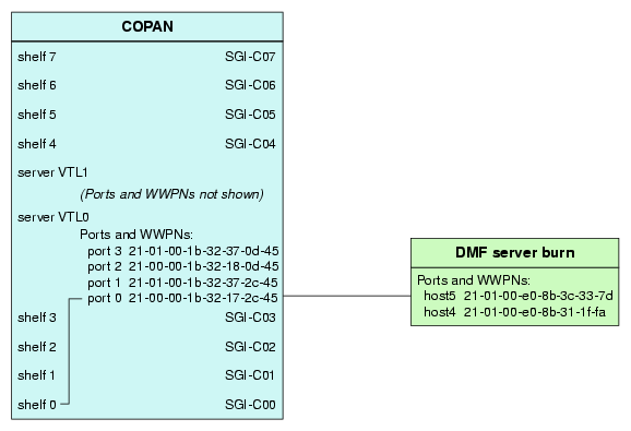
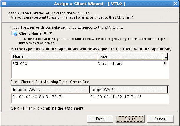
Note: Take note of the target WWPN you select here. You will use it later to identify the shelf when configuring OpenVault in step 2 of “Add an LCP for the Library”. Verify that the initiator WWPN from the DMF server corresponds to the target WWPN for the correct shelf. Click Finish to complete the configuration. Figure 3-24 shows an example. Figure 3-25 shows the relationships among the library, the DMF server initiator WWPN, and the SGI 400 VTL target WWPN.
Figure 3-25. Relationships Among the Library, the DMF Server Initiator WWPN, and the VTL Target WWPN
Log in to the DMF server and force the DMF server to scan this port for the new connection:
dmfserver# echo "- - -" > /sys/class/scsi_host/port/scan
For example, for port host5 on DMF server burn:
burn# echo "- - -" > /sys/class/scsi_host/host5/scan
On the DMF server, use the ts-lsscsi(8) command to verify that the library is visible on the port:
dmfserver# ts-lsscsi
For example, the following output shows that the SGI 400 VTL cabinet and the eight LUNs are visible, and highlights the world wide node name (WWN) and WWPN information that is displayed:
burn# ts-lsscsi
[0:0:0:0]  disk    ATA  HDS722580VLSA80  V32O  /dev/sda
[1:0:0:0]  disk    ATA  HDS722580VLSA80  V32O  /dev/sdb
...                                                                           WWN              WWPN
[5:0:0:0]  mediumx SGI  COPAN            4.50  -                       |--------------| |--------------|
[5:0:0:1]  tape    IBM  ULTRIUM-TD4   4C17  /dev/ts/pci0002:00:02.1/fc/2000001b32172c45-2100001b32172c45/lun1
[5:0:0:2]  tape    IBM  ULTRIUM-TD4   4C17  /dev/ts/pci0002:00:02.1/fc/2000001b32172c45-2100001b32172c45/lun2
[5:0:0:3]  tape    IBM  ULTRIUM-TD4   4C17  /dev/ts/pci0002:00:02.1/fc/2000001b32172c45-2100001b32172c45/lun3
[5:0:0:4]  tape    IBM  ULTRIUM-TD4   4C17  /dev/ts/pci0002:00:02.1/fc/2000001b32172c45-2100001b32172c45/lun4
[5:0:0:5]  tape    IBM  ULTRIUM-TD4   4C17  /dev/ts/pci0002:00:02.1/fc/2000001b32172c45-2100001b32172c45/lun5
[5:0:0:6]  tape    IBM  ULTRIUM-TD4   4C17  /dev/ts/pci0002:00:02.1/fc/2000001b32172c45-2100001b32172c45/lun6
[5:0:0:7]  tape    IBM  ULTRIUM-TD4   4C17  /dev/ts/pci0002:00:02.1/fc/2000001b32172c45-2100001b32172c45/lun7
...
To configure OpenVault for the library, do the following:
For more details, see OpenVault Administrator Guide for SGI InfiniteStorage.
You must add one library control program (LCP) for each virtual library. Do the following:
Stop OpenVault by using the ov_stop(8) command:
dmfserver# ov_stop
Discover the device name that maps to the SGI 400 VTL shelf by examining the output from the following ov_scandev(8) command:
dmfserver# ov_scandev -p vendor,product,serial -L
The WWPN in the output is the WWPN of the shelf assigned in step 10 of “Export Library Access to the DMF Server”. For example, for the DMF server burn, the WWPN 2100001b32172c45 (highlighted here) is shelf 0. This is the device name that you must select later in step 3d. Also note the serial number as well for confirmation in step 3e:
burn#  ov_scandev -p vendor,product,serial -L
/dev/tape/by-path/pci-0002:00:02.1-fc-0x2100001b32172c45:0x0000000000000000 SGI COPAN 8VM1O08S00
                                        |              |                              |        |
                                         --------------                                --------
                                           WWPN                                     SERIAL NUMBER
As you add libraries, they will be reflected in the ov_scandev output. For example, the following shows the output after you have added another library (the line ending in 8VM1O08S01 highlighted in this example):
burn# ov_scandev -p vendor,product,serial -L
/dev/tape/by-path/pci-0002:00:02.1-fc-0x2101001b32372c45:0x0000000000000000 SGI COPAN 8VM1O08S01
/dev/tape/by-path/pci-0002:00:02.1-fc-0x2100001b32172c45:0x0000000000000000 SGI COPAN 8VM1O08S00
Use the ov_admin command to add the LCP, using the defaults except as noted in the following example (comments below):
burn#  ov_admin                                                     ### STEP  a

What is the name of the OpenVault server? [burn]
Waiting for OpenVault to initialize ...
The OpenVault server was successfully started.

    OpenVault Configuration Menu for server "burn"

      Configuration on Machines Running LCPs and DCPs
         1 - Manage LCPs for locally attached Libraries
         2 - Manage DCPs for locally attached Drives

      Configuration on Admin-Enabled Machines
        11 - Manage Cartridge Groups
        12 - Manage Drive Groups
        13 - Import Media

      Configuration on the OpenVault Server Machine
        21 - Manage Applications
        22 - Manage OpenVault Client Machines

         q - Exit.

    Which operation would you like to do: 1                          ### STEP b


    OpenVault LCP Configuration Menu

         1 - Create a new SCSI LCP
         2 - Create a new network LCP

         r - Return to Main Menu.
         q - Exit.


    Which operation would you like to do: 1                          ### STEP  c


    OpenVault -- LCP Creation Menu

              Pathname                                                                    Library
                                                        WWPN
                                                      --------------
                                                     |              |
         1 - /dev/tape/by-path/pci-0002:00:02.1-fc-0x2100001b32172c45:0x0000000000000000

         r - Return to Previous Menu.
         q - Exit.

    For which SCSI library would you like to add a LCP: 1            ### STEP  d

Device information:

Vendor:             SGI
Product:            COPAN
Serial Number:      8VM1O08S00                                       ###  STEP e (MATCH STEP 2 ABOVE)
LCP Type:           STK-Lseries
LCP Control Path:   /dev/tape/by-path/pci-0002:00:02.1-fc-0x2100001b32172c45:0x0000000000000000

Enter a name for the device, or <enter> to use the default name [lib1] C00    ### STEP  f

Library C00 was successfully created.

What name would you like to give to this LCP? [C00@burn]

What security key would you like to give to this LCP? [none]

What polling interval would you like this LCP to use? [30]
Configuring STK-Lseries at
/dev/tape/by-path/pci-0000:08:03.0-fc-0x2101001b32372c45:0x0000000000000000
to be "C01"

What is the default shape of the slots in the library? [LTO]
For the drive at location "bottom drive",
	Enter a drive name for the element address "500": C00d1      ### STEP  g: lun1
For the drive at location "2nd drive from bottom",
        Enter a drive name for the element address "501": C00d2
For the drive at location "3rd drive from bottom",
        Enter a drive name for the element address "502": C00d3
For the drive at location "4th drive from bottom",
        Enter a drive name for the element address "503": C00d4
For the drive at location "5th drive from bottom",
        Enter a drive name for the element address "504": C00d5
For the drive at location "6th drive from bottom",
      	Enter a drive name for the element address "505": C00d6
For the drive at location "7th drive from bottom",
        Enter a drive name for the element address "506": C00d7

LCP Configuration Parameters:

Library name              :  C00
LCP name                  :  C00@burn
LCP type                  :  STK-Lseries
OpenVault Server host name:  burn
Library control path      :  /dev/tape/by-path/pci-0002:00:02.1-fc-0x2100001b32172c45:0x0000000000000000
Number of drives          :  7
Default cartridge shape   :  LTO

Drives in the Library

Drive Name      Drive Address
----------      -------------
C00d1           500
C00d2           501
C00d3           502
C00d4           503
C00d5           504
C00d6           505
C00d7           506

Create the LCP now? [Yes]

    OpenVault -- LCP Creation Menu

             Pathname                                                                     Library  LCP
           - /dev/tape/by-path/pci-0002:00:02.1-fc-0x2100001b32172c45:0x0000000000000000  C00      C00@burn

        r - Return to Previous Menu.
        q - Exit.

    For which Library would you like to add a LCP: q                      ### STEP h
Comments:
Log in to the DMF server and invoke the OpenVault administration tool:
dmfserver# ov_admin
For the SCSI library selection, enter the number associated with the device name that corresponds to the library (determined in step 2).
Confirm that the serial number (such as 8VM1O08S00 indicating shelf 0 and library SGI-C00) matches the WWPN of the device (such as 2000001b32172c45 ) that was displayed in step 2 above.
Enter the device name c0n where n matches the OpenVault library number, such as C00 for library SGI-C00.
Note: SGI recommends that you use a similar name but varying case to maintain a correspondence between the SGI 400 VTL view of the library (such as the C00 in SGI-C00) and OpenVault's view of the library (such as C00).
This is the value that is used for the MOUNT_SERVICE_GROUP parameter in the DMF configuration file. If you use a different naming scheme, you must modify the DMF configuration file. You must use a matching value later in step 3g of “Add the Set of DCPs for the Library”.Enter the drive names in turn, such as from C00d1 through C00d7 for library SGI-C00. In an SGI 400 VTL environment, these names correspond to the logical unit numbers (LUNs) for this library, lun1 through lun7.
To add the drive control programs (DCPs) for the library, do the following:
Stop OpenVault by using the ov_stop command:
dmfserver# ov_stop
Review the device name that maps to the SGI 400 VTL shelf by examining the output from the following ov_scandev command:
dmfserver# ov_scandev -p vendor,product,serial -L
For example, for the DMF server burn shelf 0, the WWPN portion of the device name (such as 2100001b32172c45 highlighted in this example) is the device name that you must verify later in step 3d.
burn#  ov_scandev -p vendor,product,serial -L
/dev/tape/by-path/pci-0002:00:02.1-fc-0x2100001b32172c45:0x0000000000000000 SGI COPAN 8VM1O08S00
                                        |              |
                                         --------------
                                           WWPN
Add the DCP, using the defaults except as noted in the following example (comments below):
burn# ov_admin                                                      ### STEP a

What is the name of the OpenVault server? [burn]
Waiting for OpenVault to initialize ...
The OpenVault server was successfully started.

    OpenVault Configuration Menu for server "burn"

      Configuration on Machines Running LCPs and DCPs
         1 - Manage LCPs for locally attached Libraries
         2 - Manage DCPs for locally attached Drives

      Configuration on Admin-Enabled Machines
        11 - Manage Cartridge Groups
        12 - Manage Drive Groups
        13 - Import Media

      Configuration on the OpenVault Server Machine
        21 - Manage Applications
        22 - Manage OpenVault Client Machines

         q - Exit.

    Which operation would you like to do: 2                          ### STEP  b

    OpenVault DCP Configuration Menu

      	 1 - Create a new DCP

         r - Return to Main Menu.
      	 q - Exit.


    Which operation would you like to do: 1                          ### STEP  c


                                                                     ### STEP  d
                                                                     ### VERIFY THAT THE
                                                                     ### WWPN MATCHES THE
                                                                     ### ov_scandev OUTPUT

    OpenVault -- DCP Creation Menu                          WWPN
                                                          --------------
             Pathname                                    |              |       Drive
         1 - /dev/ts/pci0002:00:02.1/fc/2000001b32172c45-2100001b32172c45/lun1
         2 - /dev/ts/pci0002:00:02.1/fc/2000001b32172c45-2100001b32172c45/lun2
         3 - /dev/ts/pci0002:00:02.1/fc/2000001b32172c45-2100001b32172c45/lun3
         4 - /dev/ts/pci0002:00:02.1/fc/2000001b32172c45-2100001b32172c45/lun4
         5 - /dev/ts/pci0002:00:02.1/fc/2000001b32172c45-2100001b32172c45/lun5
         6 - /dev/ts/pci0002:00:02.1/fc/2000001b32172c45-2100001b32172c45/lun6
         7 - /dev/ts/pci0002:00:02.1/fc/2000001b32172c45-2100001b32172c45/lun7

        r - Return to Previous Menu.
        q - Exit.

    For which Drive would you like to add a DCP: 1                     ### STEP  e
                                                                       ### lun1 CORRESPONDS TO DRIVE 1

Device information:

Vendor:             IBM
Product:            ULTRIUM-TD4
Serial Number:      1285424968
DCP Type:           Ultrium4
DCP Control Path:   /dev/ts/pci0002:00:02.1/fc/2000001b32172c45-2100001b32172c45/lun1

Enter a name for the device, or <enter> to use the default name [tape1] C00d1  ### STEP  f
                                                                               ### MATCH THE DRIVE NAME

The following Drive Groups currently exist:

	drives

What Drive Group do you want to use (or create)? [drives] C00                  ### STEP g
                                                                               ### ENTER A NAME THAT
                                                                               ### ASSOCIATES TO THE
                                                                               ### LIBRARY NAME

What is the unload delay time for this Drive Group? [0]

    Select an Application which should be granted access to this Drive Group

       	 1 - ov_umsh
      	 2 - dmf

      	 d - Done (no more selections).

    Which item would you like to select: 2                                      ### STEP  h

Application "dmf" now has access to Drive Group "C00".

    Select another Application which should be granted access to this Drive Group

         1 - ov_umsh

         d - Done (no more selections).

    Which item would you like to select: d                                     ### STEP i

Drive C00d1 was successfully created.

What name would you like to give to this DCP? [C00d1@burn]

    OpenVault -- DCP Creation Menu

             Pathname                                                           Drive  DCP
           - /dev/ts/pci0002:00:02.1/fc/2000001b32172c45-2100001b32172c45/lun1  C00d1  C00d1@burn
         1 - /dev/ts/pci0002:00:02.1/fc/2000001b32172c45-2100001b32172c45/lun2
         2 - /dev/ts/pci0002:00:02.1/fc/2000001b32172c45-2100001b32172c45/lun3
         3 - /dev/ts/pci0002:00:02.1/fc/2000001b32172c45-2100001b32172c45/lun4
         4 - /dev/ts/pci0002:00:02.1/fc/2000001b32172c45-2100001b32172c45/lun5
         5 - /dev/ts/pci0002:00:02.1/fc/2000001b32172c45-2100001b32172c45/lun6
         6 - /dev/ts/pci0002:00:02.1/fc/2000001b32172c45-2100001b32172c45/lun7

        r - Return to Previous Menu.
        q - Exit.

    For which Drive would you like to add a DCP: 1                          ### STEP  j

Device information:

Vendor:          IBM
Product:         ULTRIUM-TD4
Serial Number:   1285424969
DCP Type:        Ultrium4
DCP Control Path:   /dev/ts/pci0002:00:02.1/fc/2000001b32172c45-2100001b32172c45/lun2

Enter a name for the device, or <enter> to use the default name [tape1] C00d2
                                                                            ### REPEAT THE STEPS
                                                                            ### FOR EACH DRIVE
                                                                            ### (SUCH AS C00d2-C00d7)

...

Drive C00d7 was successfully created.

What name would you like to give to this DCP? [C00d7@burn]

    OpenVault -- DCP Creation Menu

             Pathname                                                           Drive  DCP
           - /dev/ts/pci0002:00:02.1/fc/2000001b32172c45-2100001b32172c45/lun1  C00d1  C00d1@burn
           - /dev/ts/pci0002:00:02.1/fc/2000001b32172c45-2100001b32172c45/lun2  C00d2  C00d2@burn
           - /dev/ts/pci0002:00:02.1/fc/2000001b32172c45-2100001b32172c45/lun3  C00d3  C00d3@burn
           - /dev/ts/pci0002:00:02.1/fc/2000001b32172c45-2100001b32172c45/lun4  C00d4  C00d4@burn
           - /dev/ts/pci0002:00:02.1/fc/2000001b32172c45-2100001b32172c45/lun5  C00d5  C00d5@burn
           - /dev/ts/pci0002:00:02.1/fc/2000001b32172c45-2100001b32172c45/lun6  C00d6  C00d6@burn
           - /dev/ts/pci0002:00:02.1/fc/2000001b32172c45-2100001b32172c45/lun7  C00d7  C00d7@burn

        r - Return to Previous Menu.
        q - Exit.

    For which Drive would you like to add a DCP: q                            ### STEP k
Comments:
Invoke the OpenVault administration tool:
dmfserver# ov_admin
Verify that the WWPN in the device name displayed in the LUNs matches the library for which you want to configure the DCPs, displayed in step 2 above.
Enter the menu selection number for the pathname that corresponds to the drive for which you want to add a DCP. This pathname will include the WWPN noted in step 2 above and will end with a LUN number that corresponds to the drive number, such as lun1 for drive 1.
Note: This WWPN/LUN name ordering convention is only true for SGI 400 VTL systems. For physical tape libraries, the WWPN/LUN names will be unique, but not necessarily ordered. Enter a name for the device that associates it with the library (rather than using the default name), such as C00d1 for library SGI-C00.
Enter a name for the drive group that associates it with the library (rather than using the default name), such as C00.
Note: This is the value that is used for the MOUNT_SERVICE_GROUP parameter in the DMF configuration file. This value must match the value used earlier in step 3f of “Add an LCP for the Library”. Repeat steps 3e through 3i for each successive drive group until you have completed the last drive (such as C00d7).
Restart OpenVault by using the ov_start(8):
burn# ov_start
Do the following to import the migration tapes for use by OpenVault and DMF:
View the available library and drives by using the following ov_stat(8) command:
dmfserver# ov_stat -ld
For example:
burn# ov_stat -ld
Library Name  Broken   Disabled   State     LCP State
C00           false    false      ready     ready

Drive Name  Group Access Broken Disabled SoftState HardState DCP State  Occupied  Cartridge PCL
C00d1       C00   true   false  false    ready     unloaded  ready      false
C00d2       C00   true   false  false    ready     unloaded  ready      false
C00d3       C00   true   false  false    ready     unloaded  ready      false
C00d4       C00   true   false  false    ready     unloaded  ready      false
C00d5       C00   true   false  false    ready     unloaded  ready      false
C00d6       C00   true   false  false    ready     unloaded  ready      false
C00d7       C00   true   false  false    ready     unloaded  ready      false
List the slot information to see all of the virtual tapes that can be imported.
dmfserver# ov_stat -L OV_library_name -s
The Cart ID field should be blank, indicating that no tapes (whose barcodes are listed in the PCL, physical cartridge label, column) have yet been imported. For example:
burn# ov_stat -L C00 -s
Library Name   Broken   Disabled   State     LCP State
C00            false    false      ready     ready
Library: 'C00'

Library  Slot Name  Slot Type  Occupied PCL     Cart ID
C00      slot 1000  LTO        true     C00AAA
C00      slot 1001  LTO        true     C00BAB
C00      slot 1002  LTO        true     C00CAC
C00      slot 1674  LTO        true     C00YT0
...
C00      slot 1675  LTO        true     C00ZT1
C00      slot 1676  LTO        true     C00AT2
C00      slot 1677  LTO        true     C00BT3

Library    Bay Name   Slot Type  Total Slots  Free Slots
C00        bay 1      DLT        0            0
Import the virtual tapes for the library by tape type into OpenVault and add them to DMF according to the DMF volume group (VG) name (such as vg0 for OpenVault library C00 and SGI 400 VTL library SGI-C00) by entering the following dmov_loadtapes(8) command:
dmfserver# dmov_loadtapes -t Ultrium4-800 -l OV_library_name -s tapesize_in_bytes VG_name
This command will invoke an editor session. If there are any tapes that you do not want added to the library server database, such as any that should be reserved for use by an application other than DMF, you should delete those barcodes from the list. Otherwise, you should exit the editor.
For example, for library SGI-C00, you would enter C00 (the corresponding OpenVault library name) and vg0 (the corresponding VG name for library SGI-C00 ), and specify the 698 GB volume size in bytes (698000000000 ):
burn# dmov_loadtapes -t Ultrium4-800 -l C00 -s 698000000000 vg0
...
(editor session is invoked)
Unused tapes in library C00.
Delete any you do not wish to use for allocation or volume group vg0.
C00AAA
C00BAB
C00CAC
...
(exit the editor session)
...
(wait a few moments for the process to complete)
...
Loading tapes into allocation/volume group vg0.
Creating Ultrium4-800 cartridges in cartgroup carts for vg0.
The tapes for the library are now imported and ready for use. A tape that has been imported into OpenVault can be referred to as a tape volume.
Verify that the tapes now have OpenVault cartridge IDs assigned to them by examining the output from the following command:
dmfserver# ov_stat -L OV_library_name -s
For example, the following output shows that the tape with the barcode C00AAA now has an OpenVault cartridge ID of ooA69kzOtNYADeH5 :
burn# ov_stat -L C00 -s
Library Name   Broken   Disabled   State     LCP State
C00            false    false      ready     ready
Library: 'C00'

Library  Slot Name  Slot Type  Occupied PCL     Cart ID
C00      slot 1000  LTO        true     C00AAA  ooA69kzOtNYADeH5
C00      slot 1001  LTO        true     C00BAB  ooA69kzOtNcAATXk
C00      slot 1002  LTO        true     C00CAC  ooA69kzOtNcAAwqN
...
C00      slot 1675  LTO        true     C00ZT1  ooA69kzOtSkAAQGF
C00      slot 1676  LTO        true     C00AT2  ooA69kzOtSkAAtZU
C00      slot 1677  LTO        true     C00BT3  ooA69kzOtSkABKsZ

Library    Bay Name   Slot Type  Total Slots  Free Slots
C00        bay 1      DLT        0            0
To test that OpenVault can mount a tape from the library for the dmf application, enter the following ov_mount(8) command:
dmfserver# ov_mount -A dmf -V VSN |
For example, to test that OpenVault can mount the tape with the VSN (barcode) C00BAB and then exit:
burn# ov_mount -A dmf -V C00BAB Mounted C00BAB on /var/opt/openvault/clients/handles//tEyedOqkcssi burn:/sys/class/fc_host/host5 # exit exit |
Repeat the steps in this chapter for each shelf.