The Silicon Graphics Prism Visualization System platform is a high-performance highly-scalable system running the SGI Linux + ProPack operating system. The platform is available in a number of configurations to meet your visualization and compute requirements.
This chapter introduces the two primary modules used in the system, and provides an abbreviated overview (quick start) on how to begin using your system. The following chapters elaborate on various topics relating to larger systems, configuration and cabling questions, component replacement and upgrades, basic troubleshooting, rack mounting, and connector functionality.
The most basic Silicon Graphics Prism uses two modules:
The XG2N module is a 2U rack mountable enclosure which, in addition to the two high-performance graphics pipes, adds to the host system a node board with two CPUs and four, eight, or twelve memory DIMMs. This module connects as an integral part of the system's compute/memory fabric. Though it contains CPUs and memory, the XG2N module does not have boot I/O functionality, and therefore may not be used as a standalone system.
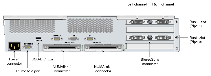
The rear panel of the XG2N module with FireGL X2PRO-256 is shown in Figure 1-1. The rear panel of the XG2N module with FireGL X3-256 is shown in Figure 1-3.
The XG2N module is a node-connected module, and therefore connects to the host system using NUMAlink, either directly or through an optional NUMAlink module (router). This way the XG2N module becomes an integral part of the system, and can contain both CPUs and memory, in addition to graphics output capabilities. Note that NUMAlink routers may be available only with specific system configurations. Check with your SGI sales or service representative for information on available configurations.
Each XG2N module contains two graphics pipes, each capable of supporting two display devices. In systems with only two pipes, the pipe and channel designations are defined as in Figure 1-1 and Figure 1-3. In systems with more than one XG2N graphics module the pipes are numbered as shown in Figure 1-2 and Figure 1-4.
Figure 1-1. Rear View of XG2N Graphics Module with FireGL X2PRO-256 (Showing First Module Pipe Numbering)
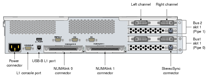 |
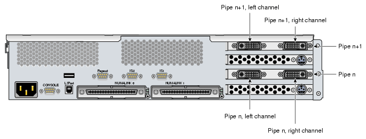
Figure 1-3. Rear View of XG2N Graphics Module with FireGL X3-256 (Showing First Module Pipe Numbering)
 |

This section describes the front panel controls and indicators of the XG2N and compute modules as shown in Figure 1-5.
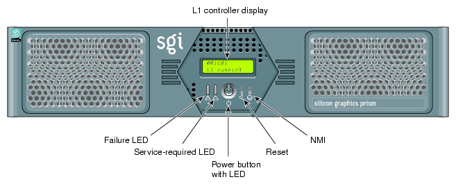
The front panels of the modules have the following controls:
L1 controller display. A liquid crystal display (LCD) that shows status and error messages generated by the L1 controller.

Note: Refer to the SGI L1 and L2 Controller Software User's Guide (007-3938-00x) for more information on the L1 controller. Status LEDs. The front panel has the following LEDs:
Power-button LED. This green LED illuminates when the internal components are on.
Service-required LED. This amber LED illuminates to indicate that an item is not functioning properly (for example, a fan is off), but the system is still operating.
Failure LED. This red LED illuminates to indicate that a failure has occurred and the system or module has shut down.
Power button. Press this button to power on the individual module. Alternatively, you can power on all the system modules at once from an optional system console.
Reset button. Press this button to reset the internal processors and ASICs. The reset will cause a memory loss.
NMI button. Pressing this button issues a non-maskable interrupt command to a module. When the system hangs, you can send the affected module an NMI interrupt. The interrupt goes to PROM and causes the CPU state to be captured for that module. This information is saved in flash PROM and in the system log, and can assist SGI technicians in debugging system hangs and customer problems.
Figure 1-6 shows a view of the rear panel of a Silicon Graphics Prism compute module.
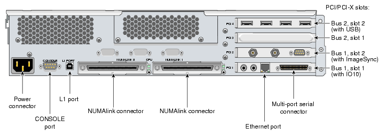
The rear panel of the module has the following items:
AC power input. This connector connects the graphics module to an AC power outlet.
Console port. This DB–9 serial port (console and diagnostic port) enables you to connect a system console to the L1 controller on the graphics module.
L1 port (USB type B). This universal serial bus (USB) type B connector connects the graphics module L1 controller to an optional L2 controller.
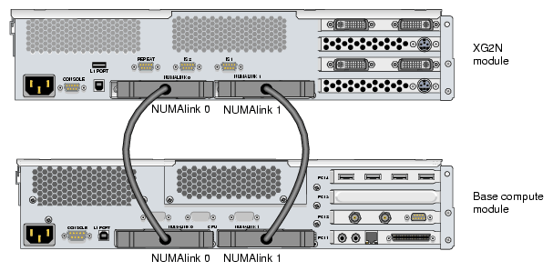
NUMAlink connectors. These NUMAlink connectors are used to connect base compute, XG2N, CPU expansion, or CMPX modules to each other or to optional router modules. These connections are made with a NUMAlink cable at 3.2 GB/s in each direction.
NUMAlink LEDs. Each NUMAlink connector has a yellow LED and a green LED (both located to the right of the NUMAlink connector). These LEDs provide information about this specific NUMAlink connection:
The yellow LED illuminates when this module and the module to which this port is connected are both powered on.
The green LED illuminates when a link has been established to another module through this NUMAlink connector.
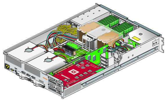
Figure 1-7 shows an internal view of the XG2N module.
Before you install a Silicon Graphics Prism, you should familiarize yourself with the safety precautions discussed in the following subsections:
During the installation of the computer system, be alert for hazard advisory statements with icons, which signify the following:
Caution Indicates a potentially hazardous situation that, if not avoided, can result in minor or moderate injury. A caution statement also alerts you to unsafe practices that can result in equipment damage and/or data corruption. A caution message is accompanied by an icon as shown in the following example:

Caution: Warning indicates a potentially hazardous situation that, if not avoided, could result in death or serious injury. A warning message is accompanied by icon as shown in the following example:

Warning:
Observe electrostatic discharge ( ESD) precautions during the entire installation process to eliminate possible ESD damage to the equipment. Wear an SGI-approved wrist strap when you handle an ESD-sensitive device. Connect the wrist strap cord directly to earth ground.
| Caution: Observe all ESD precautions. Failure to do so can result in damage to the equipment. |
Observe the following safety measures when you install the system:
Use caution when you remove the system from the shipping crate. Failure to handle the system carefully can result in personal injury or property damage.
Warning: Ensure that the shipping crate is positioned close to its destination before you unpack the crate. Warning: Employ a minimum of two people to lift the module or modules off the shipping pallet, to move the module(s) from one location to another, and to install the module(s) in a rack. Otherwise, someone could be seriously injured. Do not move the system while it is connected to power.
Warning: Keep fingers and conductive tools away from high-voltage areas. Failure to follow these precautions will result in serious injury or death. The high-voltage areas of the system are indicated with high-voltage warning labels. Ensure that a qualified electrician has properly installed the power receptacles.
Set all circuit breakers to the OFF (O) position before you plug in the system power cord.
Warning: Use the following guidelines to prevent the rack from toppling over. Otherwise, people could be seriously injured and/or equipment could be damaged.
Follow these guidelines to prevent the rack from toppling over:
Make sure that only one module is extended out of the rack at one time.
Install all equipment in the lowest available position in the rack.
Ensure that the tip tray is bolted to the front of the rack.
The following sections and illustrations are intended to guide a knowledgeable user through the installation, setup, and simple configuration of a basic Silicon Graphics Prism visualization system. For more detailed information on system components or maintenance, go on to the chapter that covers your detailed requirements.
Depending on the system ordered, your visualization system may have been shipped as two or more individual modules, or pre-mounted in a rack.
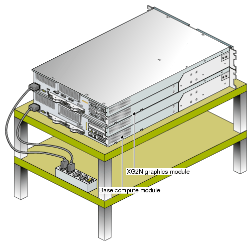
If the system was shipped as a number of individual chassis, they may be placed on a flat surface, as shown in Figure 1-8, or placed in a rack. For instructions on mounting modules in a rack see Appendix B, “Installing Silicon Graphics Prism Modules Into a Rack”.
If your system was shipped pre-mounted in a rack, see Appendix C, “Installing Rack Systems” for important information regarding unloading, unpacking, and installing a rack system.
| Warning: Follow the guidelines in “Safety Measures” and Appendix C, “Installing Rack Systems” to avoid damage to equipment, injury, or death. |
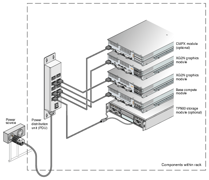
Plug your system into a suitable power outlet, as shown in Figure 1-8 (for non-racked chassis) or Figure 1-9 (for racked chassis). Refer to Appendix A, “Technical Specifications” for detailed power requirements for the system modules.
If your system was shipped from SGI with the modules already mounted in a rack and the NUMAlink cables pre installed, you should proceed to “Optional SGI ImageSync Cabling” to continue.
This section describes the NUMAlink cabling for the basic configuration. For additional NUMAlink cabling information, see “System Configurations” in Chapter 3.
Figure 1-10 shows a system with a base compute module and one XG2N graphics module.
If your system was shipped from SGI with the modules already mounted in a rack and the SGI ImageSync (IS) cables pre-installed, you should proceed to the next section, “Connecting a Monitor”, and continue with the setup.
| Note: When using an ImageSync card a monitor must be connected to the left channel of the first pipe to which the ImageSync card is cabled. |
If your system did not come with SGI ImageSync cables pre installed, use the following steps to install them:
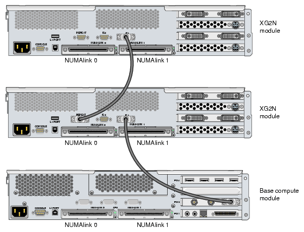
Connect the DB9 connector on the IS card in your base compute module to the SGI ImageSync DB9 connector (labeled IS1) located above the NUMAlink 1 connector on the back of the XG2N using an SGI ImageSync DB9-to-DB9 cable.
Daisy-chain the SGI ImageSync cable from this first XG2N to any additional graphics modules in your system by connecting an ImageSync DB9-to-DB9 cable from the Repeat connector (located above the NUMAlink 0 connector) and routing it to the ImageSync connector (labeled IS1) on the back of the next XG2N graphics module, as shown in Figure 1-11.
Note: Figure 1-11 is intended only to show an example of how the ImageSync cables connect. Your system may be configured differently. Caution: Although the image sync subsystem uses DB9 connectors, these connectors, whether on the ImageSync card or on the XG2N modules, are not serial ports. Connecting a serial device to these connectors may cause damage to both the ImageSync devices and the serial devices.
Select the monitor on which you want the Linux OS console to appear, and connect this monitor to the left channel of pipe 0 on your graphics module. The connector for the left channel of pipe 0 is located in the lower left section of the PCI graphics area on the back of your primary system graphics module. See Figure 1-1 for reference.
If you have a single XG2N graphics module, pipe 0 will be located in that module.
If you have multiple XG2N graphics modules, pipe 0 will typically be in the XG2N module located directly above the base compute module. The Silicon Graphics Prism platform comes with a choice of optional monitor types and sizes.
| Caution: Ensure that the electrical rating on the monitor label matches the outlet voltage range (100–120 VAC or 220–240 VAC) before you plug in the monitor. |
If you use a monitor in locations that do not have the appropriate outlets, contact your SGI system support engineer (SSE) before plugging in the monitor power cable.
Plug in and turn on your monitor or display as described in the documentation that accompanies your monitor.
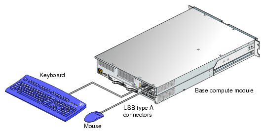
Connect a USB keyboard and a USB mouse to your system, as shown in Figure 1-12. The USB port closest to the side of the chassis is port 1.
| Note: Some system configurations may be limited to the use of one keyboard and mouse set. Check with your SGI sales or service representative if you have questions regarding the use of multiple keyboards and mice with your system. |
Figure 1-12 shows the USB PCI card in bus 2, slot 2 (the top PCI slot) of the base module, which is the preferred location for this card. Some configurations may have the USB card in a different PCI slot in the host system.
| Note: If your keyboard/mouse pair will be further than 10 feet (3 meters) away from the USB ports on the system, please refer to the section “Optional USB Extender” in Chapter 2 for details about how to connect these devices through a USB extender. |
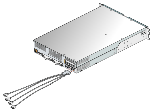
A multi-port serial cable that converts the serial output on the IO10 board into four DB-9 serial cables is included with each base compute module containing an IO10.
Figure 1-13 shows an example connection.
| Note: Leave the multi-port serial adapter cable unplugged if you are not using it for optional serial connections. |
Connect a serial terminal to the Level 1 console connector on the base compute module as shown in Figure 1-14.
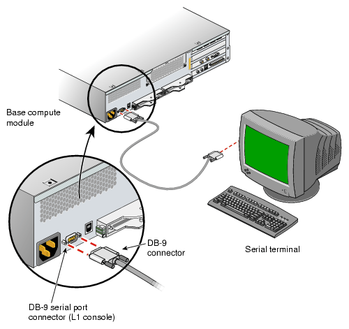
If your Silicon Graphics Prism does not have a a local system console, you can manually power it on and off by using the power buttons. To power on your system or an individual module manually, follow these steps:
If the monitors and other peripherals are equipped with voltage select switches, verify that they are set for the appropriate AC voltage and plug them in. Note that they are normally plugged into power sources outside a rack system.
Turn on the circuit breaker switch of the PDU if applicable.
Press the power buttons on each of the modules that you want to power on in the following order:
For the optional TP900 storage module, press the rear-panel power button to ON (I).
Power on all the XG2N graphics modules.
Power on any optional compute expansion or CMPX modules.
Power on the base (system) compute module last.
To boot the system from the L1 interface you must have a console connected to the system via the console port on the base compute module. The serial connection parameters are:
38400 baud
1 stop bit
no parity
Use the following command at the L1 prompt to bring up all the system modules:
001c01-L1> * power up
If the system does not boot, recheck all power, and cable connections to be sure they are properly plugged in. See Chapter 5, “Troubleshooting” for additional trouble shooting tips and L1 messaging.
To contact the SGI Customer Service Center, call 1-800-800-4SGI, or visit http://www.sgi.com/support/customerservice.html. From outside the United States contact your local SGI sales office.
Once your Silicon Graphics Prism Visualization System is installed in a rack (or otherwise situated), is cabled together via NUMAlink, and is powered on, you should verify that all modules are being seen by Linux + ProPack. To do this, follow these steps:
From a Linux prompt, type hinv <Enter>
To verify the connection of all the graphics modules check the output for lines similar to the following examples:
VGA compatible controller: ATI Technologies Inc Radeon R350 NG [FireGL X2] (rev xxx). on pci11.01.0
Display controller: ATI Technologies Inc Radeon R350 [FireGL X2] (Secondary) (rev xxx). on pci11.01.1
VGA compatible controller: ATI Technologies Inc Radeon R350 NG [FireGL X2] (#2) (rev xxx). on pci12.01.0
Display controller: ATI Technologies Inc Radeon R350 [FireGL X2] (Secondary) (#2) (rev xxx). on pci12.01.1To verify all graphics boards in the system are seen, count the number of entries in the output similar to the example output in step 2. Each two-line entry represents one graphics pipe.
If the output does not show all the graphics pipes present, recheck all power, and cable connections to be sure they are properly plugged in. See Chapter 5, “Troubleshooting” for additional trouble shooting tips and L1 messaging.
To confirm the presence of the graphics boards in the system using a Linux command-line, use the following:
Enter /sbin/lspci from a Linux prompt.
Check the output for information similar to the following:
11:01.0 VGA compatible controller: ATI Technologies Inc Radeon R350 NG [FireGL X2] (rev xx)
11:01.1 Display controller: ATI Technologies Inc Radeon R350 [FireGL X2] (Secondary) (rev xx)
12:01.0 VGA compatible controller: ATI Technologies Inc Radeon R350 NG [FireGL X2] (rev xx)
12:01.1 Display controller: ATI Technologies Inc Radeon R350 [FireGL X2] (Secondary) (rev xx)If the output does not show all the graphics pipes present, recheck all power, and cable connections to be sure they are properly plugged in. See Chapter 5, “Troubleshooting” for additional trouble shooting tips and L1 messaging.
To power off your system manually, follow these steps:
| Caution: If you power off the system before you halt the operating system, you can lose data. |
Shut down the operating system by entering the following command:
# init 0
Press the power buttons or power switches on each of the modules that you want to power off. You may power off the modules in any order:
To power off the TP900 storage module, press the power button on its rear panel to the OFF (O) position.
To power off the base compute, XG2N, expansion compute, or CMPX module, press the power button on the front panel of each module.