This chapter describes the configuration ranges of the Silicon Graphics Prism Power and Team Systems and provides NUMAlink cabling instructions.
The minimum and maximum ranges of the configurable items for the Silicon Graphics Prism Power Systems ( ring topology) are listed in Table 3-1, and for the Silicon Graphics Prism Team Systems ( router topology) are listed in Table 3-2.
Table 3-1. Silicon Graphics Prism Power System Configuration Ranges
| Configuration | Configuration |
|---|---|---|
Compute/expansion modules | 1 | 3 |
Graphics modules | 1 | 2 |
Processors | 4 | 8 |
Memory capacity | 2 GB | 96 GB |
Internal disk storage | 1 serial ATA disk | 6 serial ATA disks |
Internal PCI/PCI–X slots[b] | 4 | 16 |
Storage device | None | Customer configurable |
17U short rack 39U tall rack | None None | 1 1 |
Optional L2 controller | None | 1 |
[a] Maximum configurations and peak performance will change over time based on new technology available; check with your SGI sales or service representative for the latest available options and configurations. [b] Each base compute module has four internal PCI/PCI–X slots; however, one slot is required for the base IO PCI card, one for the ImageSync card, and one for USB. Therefore, the number of available slots in the base compute module is reduced. | ||
Table 3-2. Silicon Graphics Prism Team System Configuration Ranges
| Configuration | Configuration |
|---|---|---|
Compute/expansion modules | 1 | 5 |
Graphics modules | 2 | 4 |
NUMAlink modules (routers) | 2 | 2 |
Processors | 8 | 16 |
Memory capacity | 8 GB | 192 GB |
Internal disk storage | 1 serial ATA disk | 10 serial ATA disks |
Internal PCI/PCI–X slots[b] | 4 | 28 |
Storage device | None | Customer configurable |
17U short rack 39U tall rack | None None | 1 2 |
Optional L2 controller | None | 1 |
[a] Maximum configurations and peak performance will change over time based on new technology available; check with your SGI sales or service representative for the latest available options and configurations. [b] Each base compute module has four internal PCI/PCI–X slots; however, one slot is required for the base IO PCI card, one for the ImageSync card, and one for USB. Therefore, the number of available slots in the base compute module is reduced. | ||
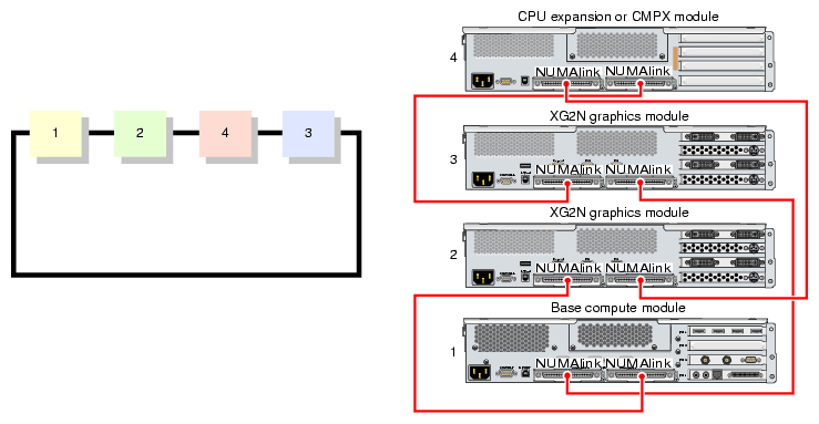
The basic Silicon Graphics Prism uses a type of network configuration that is referred to as a ring topology. As the name implies, the network connection between the base compute module, graphics module, and optional CPU expansion or CMPX modules forms a ring. A message is passed around the ring until it reaches its destination. The data flow of this ring topology flows in both directions, enabling the modules to have direct connection to two other modules and providing an alternative path if a connection fails between two modules.
The Silicon Graphics Prism system may also be configured in routed configurations, which are described in “NUMAlink Cabling in Routed Systems”.
The bisection bandwidth per node depends on the number of modules on the ring, as well as what type of modules they are; the bisection bandwidth per node is greatest when there are only two modules on the ring. See Table 3-3.
Table 3-3. Bisection Bandwidth of Ring Topology
Module Count | Bisection Bandwidth |
|---|---|
2 | 3.2 GB/s/node |
3 (with 2 pipes) | 2.13 GB/s/node |
3 (with 4 pipes) | 1.83 GB/s/node |
4 (with 2 pipes) | 2.13 GB/s/node |
4 (with 4 pipes) | 1.6 GB/s/node |
Figure 3-1 provides an example of the two-module ring topology.
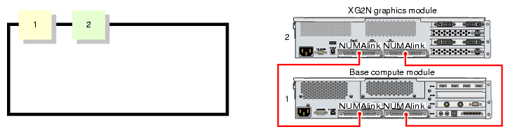
Figure 3-2 shows an example of a three-module ring topology.
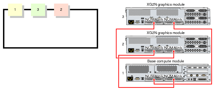
Figure 3-3 shows an example of a four-module ring topology.
This section describes the NUMAlink cabling for systems containing routers.
Prism systems containing routers will have between four and eight base compute, XG2N, CPU, or CMPX modules, as well as two routers. This section provides cabling details for the smallest configuration (four modules, two routers) and largest configuration (eight modules, two routers). Other configurations are similar to the ones shown.
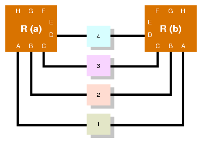
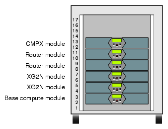
This section describes a minimum routed configuration, having four base compute, XG2N, CPU, or CMPX modules. Table 3-4 details the NUMAlink cabling for this configuration, Figure 3-4 provides a conceptual diagram, and Figure 3-5 shows a representative module ordering.
Table 3-4. Minimum Routed Configuration Cable Chart
Router (a) Cables | Router (b) Cables |
|---|---|
Router (a), port A to module 1, port NL-0 | Router (b), port A to module 1, port NL-1 |
Router (a), port B to module 2, port NL-0 | Router (b), port B to module 2, port NL-1 |
Router (a), port C to module 3, port NL-0 | Router (b), port C to module 3, port NL-1 |
Router (a), port D to module 4, port NL-0 | Router (b), port D to module 4, port NL-1 |
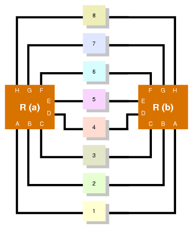
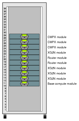
This section describes a maximum routed configuration, having eight base compute, XG2N, CPU, or CMPX modules. Table 3-5 details the NUMAlink cabling for this configuration, Figure 3-6 provides a conceptual diagram, and Figure 3-7 shows a representative the module ordering.
Table 3-5. Maximum Routed Configuration Cable Chart
Router (a) Cables | Router (b) Cables |
|---|---|
Router (a), port A to module 1, port NL-0 | Router (b), port A to module 1, port NL-1 |
Router (a), port B to module 2, port NL-0 | Router (b), port B to module 2, port NL-1 |
Router (a), port C to module 3, port NL-0 | Router (b), port C to module 3, port NL-1 |
Router (a), port D to module 4, port NL-0 | Router (b), port D to module 4, port NL-1 |
Router (a), port E to module 1, port NL-0 | Router (b), port E to module 1, port NL-1 |
Router (a), port F to module 2, port NL-0 | Router (b), port F to module 2, port NL-1 |
Router (a), port G to module 3, port NL-0 | Router (b), port G to module 3, port NL-1 |
Router (a), port H to module 4, port NL-0 | Router (b), port H to module 4, port NL-1 |