Depending on how you purchased your Silicon Graphics Prism visualization system, you may need to install one or more modules in a rack or move modules within a rack. This Appendix describes:
The rack locations for your XG2N and other modules will be partially determined by cable lengths and routings.
Since the Silicon Graphics Prism is a highly-configurable system, it is not practical to list every possible configuration. For valid configurations not shown in Chapter 3, “Configurations and Cabling” consult your SGI sales or support representative.
For power connection examples, see “Positioning and Power for Your Silicon Graphics Prism” in Chapter 1.
Each module in a system contains a Level 1 controller (L1). This controller should be programmed with the location of the brick in which it is installed. Programming the L1 with the correct rack and slot numbers allows for easier system maintenance and diagnostics, and is necessary for predictable operation of the system.
When a module is connected to AC power, the L1 display will indicate its position by displaying a string of the form XXXyZZ (for example, “001c12”).
Decode this string as follows:
“XXX” is the rack number (in this example, rack 001)
“y” is the module type (in this case, c indicates a compute module)
“ZZ” is the “U” number within that rack, counting from the bottom (in this case, slot 12).
If the position indicated on an L1 display is not correct, you should correct it as follows:
Connect a serial terminal to the console port on the brick in question.
Display the current location setting in the L1:
001c12-L1> brick
rack: 001 slot: 12 partition: 0 type: C source: EEPROM
001c12-L1> brick rack 1
brick rack set to 001
-
001c12-L1> brick slot 7
brick slot set to 07
Verify the newly entered information:
001c12-L1> brick
rack: 001 slot: 07 partition: 0 type: C source: EEPROM
If other bricks need to be changed, repeat steps 1 through 4 for each additional brick.
This section describes how to install or remove a module in a rack using slide rails.
This rackmounting information is found in the following sections:
This section describes how to rackmount modules with slide rail assemblies and includes the following topics:
Table B-1 specifies the space requirements when rackmounting a module in a 19-inch rack.
Table B-1. Rackmounting Space Requirements for Modules
Height | 3.44 inches (8.74 cm) |
Width | 17.06 inches (43.33 cm) |
Depth | 27 inches (68.58 cm) (with bezel) |
Weight | 50 lb. (22.7 kg) maximum configuration[a] |
Required front clearance for module | 8.25 inches (20.96 cm) |
Required rear clearance for module | 10 inches (25.40 cm) |
Required side clearance for module | right side: 6 inches (15.24 cm) |
Required front clearance for rack | 36 inches (91 cm) |
Required rear clearance for rack | 36 inches (91 cm) |
[a] Weight will vary depending on configuration of memory, PCI cards, and disks. | |
Table B-2 lists the hardware that you will use to mount each module in a 19-inch rack.
Table B-2. Slide Rail Rackmounting Hardware
Hardware Type | Qty | Usage |
|---|---|---|
Slide rail assembly (includes chassis rail) | 2 | Allows the module to slide in and out of rack. |
2-inch rear mounting bracket | 2 | Mounts the slide rails to the rear rack rails. |
10-24 x 1/4-inch Phillips screw | 10 | Secures the chassis rails to the module. |
10-32 x 1/2-inch Phillips screw | 8 | Secures the slide rails to the rack rails. |
10-32 x 1/2-inch Phillips screw | 4 | Secures the slide rails to their mounting brackets. |
10-32 clip nut | 2 | Provides a threaded hole for fastening the module front panel to the rack rails. |
10-32 x 1/2-inch Phillips screw | 2 | Fastens the module front panel to the clip nut. |
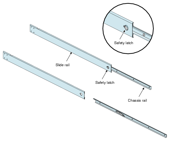
The slide rail assembly consists of a chassis rail and a slide rail. You need to remove the chassis rail from the slide rail so that you can install a mounting bracket to the slide rail and attach the chassis rail to the module (see “Preparing the Module”). To remove the chassis rail from the slide rail, follow these steps:
Remove the two slide rail assemblies and the rear mounting brackets from the shipping container.
Extend each slide rail assembly until the safety latch snaps into place.
Press the safety latch and remove the chassis rail from the slide rail, as shown in Figure B-1.
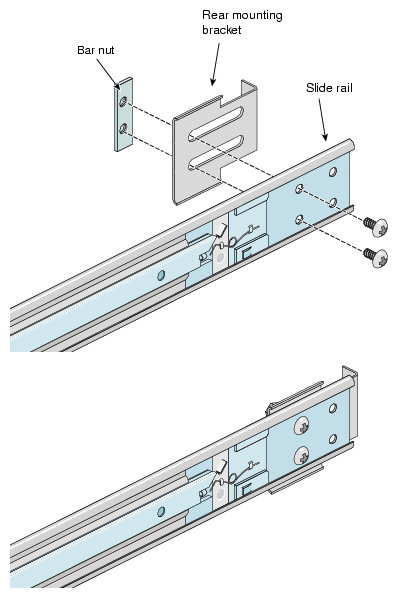
Place one of the mounting brackets on the back of the slide rail as shown in Figure B-2. Adjust the position of the mounting bracket on the slide rail according to the depth of the rack.
Place a bar nut next to the mounting bracket. Secure the mounting bracket to the slide rail by inserting two 10-32 x 1/2-inch screws through the assembly and into the bar nut as shown in Figure B-2.
Repeat steps 4 and 5 to attach a mounting bracket to the other slide rail.
To attach the chassis rails to the module, follow these steps:
Place the module on a flat, stable surface.
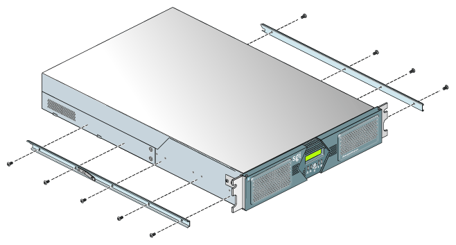
Using four 10-24 x 1/4-inch screws, attach one of the chassis rails to the right side of the module chassis. Ensure that the rail is installed in the correct direction (see Figure B-3).

Caution: Use only the 1/4-inch (0.64 cm) length screws. Longer screws damage internal components in the module. Using five 10-24 x 1/4-inch screws, attach the second rail to the left side of the module chassis. Again, ensure that the rail is installed in the correct direction.
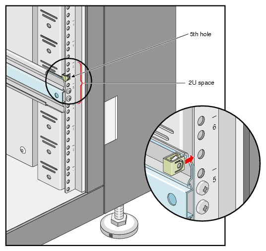
The module requires two units (2U) of space within the rack (one unit is equivalent to 1.75 inches [44.5 cm]). To determine where you should install the slide rails in the rack, you must count mounting holes. Each U contains three mounting holes; therefore, in the 2U of space that the module occupies, there are six mounting holes. The bottom hole of the 2U space is hole 1. The top mounting hole in the 2U space is hole 6. See Figure B-4.
 | Note: A module in the rack is identified by the lowest U number that it occupies. For example, in Figure B-4 the module resides in U5 (the fifth unit within the rack). |
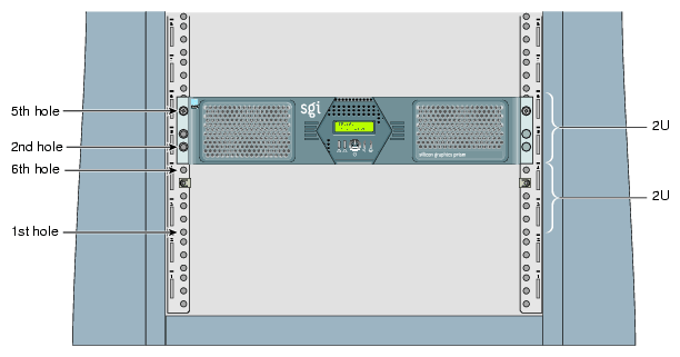
To determine how many mounting holes you must count, use the following formula:
3 x (the lowest U number that the module will occupy) - 2.
For example, when you want to install the module in locations U9 and U10, count 25 mounting holes (3 x 9 - 2) starting from the bottom of the rack. The 25th hole is the first mounting hole of U9.
To attach the slide rail to the rack, follow these steps:
 | Tip: The slide rails must be level in the rack. To ensure that you install the slide rails correctly, carefully count the mounting holes on all of the rack rails (the two front rails and the two rear rails). |
Locate eight 10-32 x 1/2-inch Phillips screws, eight shoulder washers, and four bar nuts.
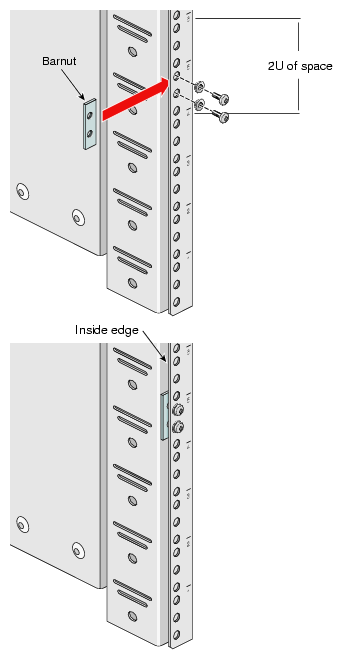
Place one of the bar nuts inside the rack and align it with the second and third holes of the selected 2U of space (see Figure B-5).
Note: The holes in the bar nuts are not centered. The bar nuts need to be placed in such a way that the holes are closest to the inside edge of the rack rails. See Figure B-5. Insert two screws with shoulder washers through the rack rail to hold the bar nut in place. The screws should not be tightened at this point.
Repeat steps 2 and 3 to install the remaining three bar nuts on the other three rack rails (front and rear of rack).
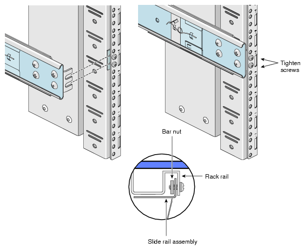
Insert the front and rear brackets of one of the slide rails between the rack rails and the bar nuts, as shown in Figure B-6.
Tighten the screws on the front- and rear-end of the rails. Do not tighten firmly at this point, because all screws will be firmly tightened once the module is installed in the rack.
Repeat steps 5 and 6 to attach the second slide rail to the other side of the rack.
Clip nuts secure the modules to the rack. To install the clip nuts, slide the clip nuts over the fifth hole of the selected 2U of space on each of the front rails. See Figure B-7 for details.
To install the module in the rack, follow these steps:
| Note: Step 2 requires two people. |
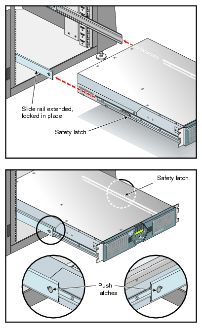
Fully extend the left and right slide rails from the rack until they lock into place.
With one person holding each side of the module, align the chassis rails of the module with the slide rails of the rack.
Slide the chassis rails into the slide rails until the chassis rails are stopped by the safety latches.
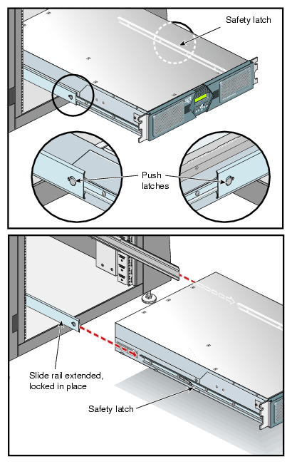
Press the safety latches on both sides of the module to fully seat the chassis rails into the slide rails (see Figure B-8).
Firmly tighten all screws (the eight screws that secure the slide rails to the rack rails).
Secure the module to the rack by inserting a 10-32 x 1/2-inch Phillips screw in the top hole of each chassis ear (see Figure B-9).
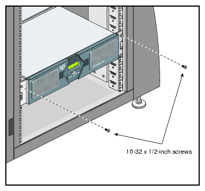
Once the module is installed in the rack, you can adjust the position of the module in the rack (up and down, side-to-side). To adjust the position of the module, loosen the front mounting screws, adjust the module to the desired position, then tighten the mounting screws.
| Caution: Do not lift the module by its bezel; it is not designed to handle the weight of the module. Instead, use the chassis ears to move the module (see Figure B-9). |
To remove a module from a rack, follow these steps:
Power off the module.
Disconnect all of the cables at the rear of the module.

Warning: Components may be hot. To avoid injury, allow the components to cool for approximately five minutes before you proceed with these instructions. Remove the two screws that secure the module to the front rails of the rack.
Carefully pull the module from the rack until it is stopped by the safety latches.
With one person holding each side, release the safety latches on both sides of the module and pull the module out of the slide rail (see Figure B-10).
Place the module on a flat, stable surface.
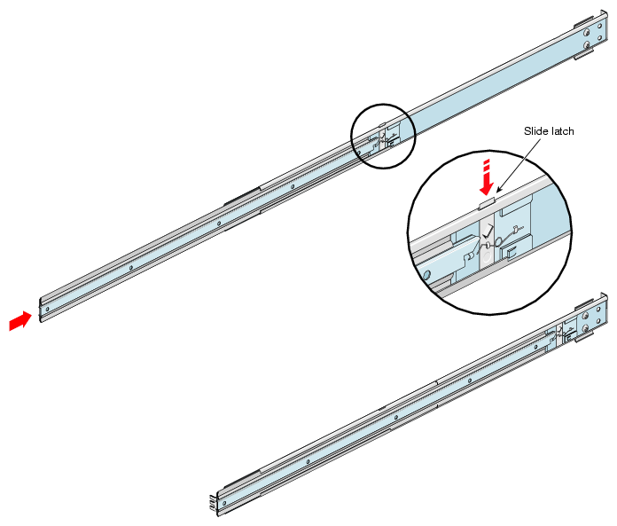
To slide the slide rails back into the rack, push down on the slide latches as shown in Figure B-11.
Note: Before you reinstall a module into the rack, fully extend the slide rails from the rack until they lock into place.