This appendix contains technical specification information about your system, as follows:
Table A-1 lists the environmental specifications of the Silicon Graphics Prism.
Table A-1. Environmental Specifications
Characteristic | Specification |
|---|---|
Temperature, | +5 ºC (+41 ºF) to +35 ºC (+95 ºF) (up to 1500 m [5,000 ft]) |
Temperature, | -40 ºC (-40 ºF) to +60 ºC (+140 ºF) |
Humidity | 10% to 95% RH, noncondensing |
Altitude | Sea level to 40,000 ft (12,000 m) (nonoperating) |
Table A-2 lists the bandwidth characteristics of the compute module.
Table A-2. Bandwidth Characteristics of the Compute Module
Characteristic | Peak Bandwidth | Sustainable Bandwidth |
|---|---|---|
NUMAlink channel | 6.4 GB/s full duplex | ~2.8 GB/s each direction |
Main memory | Up to 10.8 GB/s | Up to 10.8 GB/s |
Front Side Bus (FSB) | 6.4 GB/s | ~6.4 GB/s |
Table A-3 summarizes the general features of the compute module.
 | Note: The expansion compute module does not include an optional IO10 PCI card. |
Table A-3. General Features of the Compute Module
Feature | Base Compute Module | Expansion Compute Module |
|---|---|---|
NUMAlink ports | 2 (3.2 GB/s each direction) | 2 (3.2 GB/s each direction) |
Serial console port | 1 | 1 |
L1 port | 1 | 1 |
RT interrupt input port | 1 (not functional under Linux) |
|
RT interrupt output port | 1 (not functional under Linux) |
|
Ethernet port | 1 10BaseT/100BaseT/1000BaseT |
|
Serial RS232/422 (4 ports) | 4 serial ports (external) |
|
serial ATA port (internal) | 2 serial ATA |
|
3.5-in. drive bay | 1 or 2 |
|
64-bit Intel processor | 2 | 0, 1, or 2 |
Memory | up to 24 GB | up to 24 GB |
Expansion slot | 2 PCI-X | 4 PCI-X |
| Note: Power consumption in the XG2N module is slightly higher (approximately 563 watts) than in the base compute module. The XG2N always requires use of two power supplies at all times. Otherwise, the basic physical and electrical specifications are the same. |
Table A-4 lists the physical specifications for the compute module.
Table A-4. Compute Module Physical Specifications
Characteristic | Specification |
|---|---|
Height | 3.44 in. (8.74 cm) |
Width | 17.06 in. (43.33 cm) |
Depth | 27 in. (68.58 cm) (with bezel) |
Weight | 50 lb (22.7 kg) maximum configuration[a] |
Noise | 6.0 Bells sound power, up to 30 ºC |
Heat dissipation | 1315 Btu/hr maximum |
Input power | 120 - 240 VAC |
[a] Weight will vary depending on whether the system has one or two power supplies, on the amount of DIMMs installed, and on whether you have one or two disk drives in your system. | |
Table A-5 lists the bandwidth characteristics of the CMPX module.
Table A-5. Bandwidth Characteristics of the CMPX Module
Characteristic | Peak Bandwidth | Sustainable Bandwidth |
|---|---|---|
NUMAlink channel | 6.4 GB/s full duplex | ~2.8 GB/s each direction |
Main memory | Up to 10.8 GB/s | Up to 10.8 GB/s |
Front Side Bus (FSB) | 6.4 GB/s | ~6.4 GB/s |
Table A-6 lists the specifications for the CMPX module.
Table A-6. CMPX Module Specifications
Characteristic | Specifications |
|---|---|
Height | 3.44 in. (8.80 cm) |
Width | 17.06 in. (43.36 cm) |
Depth | 27 in. (68.58 cm) (with bezel) |
Weight | 50 lb (22.7 kg) maximum configuration[a] |
Input voltage | 120 - 240 VAC |
[a] Weight will vary slightly depending on whether the module has processors, one or two power supplies, on the number of DIMMs installed, and on PCI cards in the unit. | |
Table A-7 lists the specifications of each of the 8 router ports.
Table A-7. Router Port Specifications
Port | Quantity | Peak Transfer Rate |
|---|---|---|
NUMAlink | 8 | 3.2 GB/s each direction |
L1 | 1 | 12 Mbits/s |
Table A-8 lists the technical specifications of the router.
Table A-8. Router Technical Specifications
Characteristic | Specification |
|---|---|
Height | 3.3 in. (83.82 mm) |
Width | 17.38 in. (441.45 mm) |
Depth | 27.5 in. (698.50 mm) |
Weight | 20 lb (9.1 kg) |
Heat dissipation | 205 Btu/hr maximum |
Input power | 60 W |
The Silicon Graphics Prism modules can be housed in optional short (17U) or tall (39U) racks.
| Note: One “U” is 1.75 in. (4.45 cm). |
Table A-9 lists the specifications of the short rack.
Table A-9. Short Rack Specifications (with Skins)
Characteristic | Specification |
|---|---|
Height | 36.06 in. (916 mm) |
Width | 25.38 in. (645 mm) |
Depth | 40.63 in. (1032 mm) |
Weight (maximum) | 610 lb (277 kg) |
Shipping weight (maximum) | 685 lb (312 kg) |
Table A-10 lists the specifications of the tall rack.
Table A-10. Tall Rack Specifications
Characteristic | Specification |
|---|---|
Height | 75.82 in. (1925.83 mm) |
Width | 23.62 in. (599.95 mm) |
Depth | 41.25 in. (1048 mm) |
Weight (maximum) | 1,366 lb (620 kg) |
Shipping weight (maximum) | 1,547 lb (702 kg) |
Table A-11 lists the specifications of the SGI TP900 storage module.
Table A-11. TP900 Storage Module Specifications
Characteristic | Specification |
|---|---|
Height | 3.37 in. (85.7 mm) |
Width | 17.6 in. (447 mm) |
Depth | 21.46 in. (545 mm) |
Input power | 100 - 254 VAC (~175 W) |
Weight: Maximum configuration Empty enclosure |
48.5 lb (22 kg) 14.3 lb (6.5 kg) |
This section provides pin assignment information for the non-proprietary connectors on the following components:
Compute module (base and expansion)
XG2N module
CMPX module
TP900 storage module
Table A-12 lists the non-proprietary connectors that are located on the rear panel of the compute module (see Figure A-1). The third column of the table indicates where you can find the pin assignments for these connectors.
Table A-12. Compute Module Connectors
Port | Connector | Pin Assignments |
|---|---|---|
Optional PCI serial ports[a] | DB-9 | See Figure A-5
|
Console port | DB-9 | See Figure A-5
|
Ethernet port[b] | RJ-45 | See Figure A-6 and Table A-16
|
External serial port | IEEE 1284 36-pin MDR multi-port serial adapter | See Figure A-7 and Table A-17
|
RT interrupt input and output ports[c] | Stereo jack | Not supported under Linux |
L1 port | USB type B | See Figure A-9 and Table A-19
|
[a] Optional serial ports are available on a PCI card. [b] These connectors are available only when the compute module has an IO10 PCI card. [c] These connectors are not functionally supported under SGI Linux + ProPack. | ||
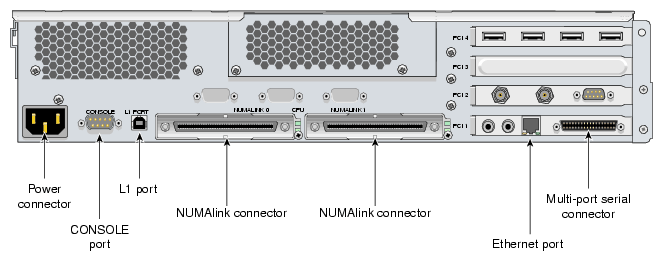
| Note: The RT interrupt input and RT interrupt output functionality of the IO10 PCI card is not supported under SGI Linux + ProPack. |
The XG2N module contains two graphics pipes, each capable of supporting two display devices. The graphics connector and pinouts are shown in Figure A-2 and Table A-13.
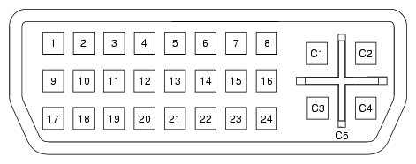
The console and L1 connectors on the XG2N module are the same as the compute module.
Table A-13. DVI-I Connector Signals and Pins
Pin | Function | Pin | Function |
|---|---|---|---|
1 | T.M.D.S.[a] Data 2- | 16 | Hot Plug Detect |
2 | T.M.D.S. Data 2+ | 17 | T.M.D.S. Data 0- |
3 | T.M.D.S. Data 2/4 Shield | 18 | T.M.D.S. Data 0+ |
4 | T.M.D.S. Data 4- | 19 | T.M.D.S. Data 0/5 Shield |
5 | T.M.D.S. Data 4+ | 20 | T.M.D.S. Data 5- |
6 | DDC Clock | 21 | T.M.D.S. Data 5+ |
7 | DDC Data | 22 | T.M.D.S. Clock Shield |
8 | Analog Vertical Sync | 23 | T.M.D.S. Clock+ |
9 | T.M.D.S. Data 1- | 24 | T.M.D.S. Clock- |
10 | T.M.D.S. Data 1+ |
|
|
11 | T.M.D.S Data 1/3 Shield | C1 | Analog Red Video Out |
12 | T.M.D.S. Data 3- | C2 | Analog Green Video Out |
13 | T.M.D.S. Data 3+ | C3 | Analog Blue Video Out |
14 | +5V Power | C4 | Analog Horizontal Sync |
15 | Ground (for +5V) | C5 | Analog Common Ground |
[a] Transition Minimized Differential Signaling | |||
Table A-14 lists the non-proprietary connectors that are located on the rear panel of the optional CMPX module (see Figure A-3). The third column of the table indicates where you can find the pin assignments for these connectors.
Table A-14. CMPX Module Connectors
Port | Connector | Pin Assignments |
|---|---|---|
Console port | DB-9 | See Figure A-5
|
L1 port | USB type B | See Figure A-9 and Table A-19
|
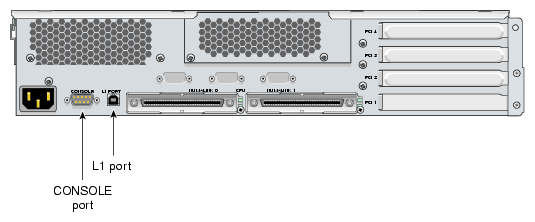
Figure A-4 shows the two SCSI port connectors on the rear panel of the TP900 storage module.
Note that your system will need an optional SCSI PCI card installed to interface with the TP900 storage option module.
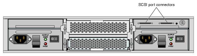
Figure A-5 shows and Table A-15 lists the DB-9 serial connector pin assignments. This connector is used for the console port of the base compute, XG2N, CPU expansion, CMPX, and router modules, and the console and modem ports of the optional L2 controller.
 | Caution: Although the image sync subsystem also uses DB9 connectors, these connectors, whether on the ImageSync card or on the XG2N bricks, are not serial ports. Connecting a serial device to these connectors may cause damage to both the ImageSync devices and the serial devices. |
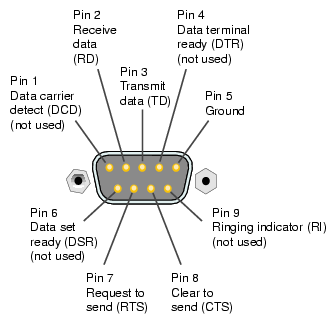
Table A-15. DB-9 Serial Connector Pin Assignments
DB-9 Connector Pin | Pin Assignment |
|---|---|
1 | Data carrier detect (DCD) (not used) |
2 | Receive data (RD) |
3 | Transmit data (TD) |
4 | Data Terminal Ready (DTR) (not used) |
5 | Ground |
6 | Data set ready (DSR) (not used) |
7 | Request to send (RTS) |
8 | Clear to send (CTS) |
9 | Ringing indicator (RI) (not used) |
Figure A-6 shows the pin locations for the RJ-45 connector on the IO10 PCI card and the L2 controller. Table A-16 shows the pin assignments for the RJ-45 connector.
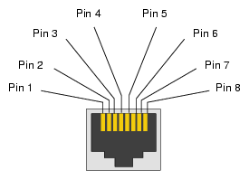
Table A-16. Ethernet Connector Pin Assignments
10/100BaseT
Ethernet Pinouts |
| 1000BaseT
Ethernet Pinouts |
|
|---|---|---|---|
1 | Transmit + | 1 | Transmit/Receive 0+ |
2 | Transmit – | 2 | Transmit/Receive 0– |
3 | Receive + | 3 | Transmit/Receive 1+ |
4 | Not used | 4 | Transmit/Receive 2+ |
5 | Not used | 5 | Transmit/Receive 2– |
6 | Receive – | 6 | Transmit/Receive 1– |
7 | Not used | 7 | Transmit/Receive 3+ |
8 | Not used | 8 | Transmit/Receive 3– |
Figure A-7 shows the connector pin locations for the multi-port serial adapter connector located on the IO10 PCI card.
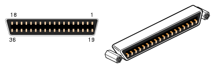
Table A-17 lists the pin assignments for the multi-port serial adapter connector.
Table A-17. Multi-port Serial Adapter Pinouts
Pin | Assignment | Pin | Assignment |
|---|---|---|---|
1 | GND | 19 | S0 DSR |
2 | S0 DCD | 20 | S0 RTS |
3 | S0 RXD | 21 | S0 CTS |
4 | S0 TXD | 22 | S0 RI |
5 | S0 DTR | 23 | GND |
6 | S1 DSR | 24 | S1 DCD |
7 | S1 RTS | 25 | S1 RXD |
8 | S1 CTS | 26 | S1 TXD |
9 | S1 RI | 27 | S1 DTR |
10 | GND | 28 | S2 DSR |
11 | S2 DCD | 29 | S2 RTS |
12 | S2 RXD | 30 | S2 CTS |
13 | S2 TXD | 31 | S2 RI |
14 | S2 DTR | 32 | GND |
15 | S3 DSR | 33 | S3 DCD |
16 | S3 RTS | 34 | S3 RXD |
17 | S3 CTS | 35 | S3 TXD |
18 | S3 RI | 36 | S3 DTR |
Figure A-8 shows the USB type A connector that is used for USB ports 1 through 4 of the optional L2 controller that connects to the compute and/or CMPX modules.
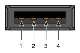
Table A-18 lists the pin assignments.
Table A-18. Pin Assignments for USB Type A Connector
Signal | Color | Pin Number |
|---|---|---|
VCC | Red | 1 |
-Data | White | 2 |
+Data | Green | 3 |
Ground | Black | 4 |
Figure A-9 shows the USB type B connector that is used for the USB L1 port of the compute module, XG2N module and the CMPX module. Table A-19 lists the pin assignments.
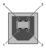
Table A-19. Pin Assignments for USB Type B Connector
Signal | Color | Pin Number |
|---|---|---|
VCC | Red | 1 |
-Data | White | 2 |
+Data | Green | 3 |
Ground | Black | 4 |