This chapter provides an overview of the physical and architectural aspects of your Silicon Graphics Prism platform. System configurations and components are described and illustrated. This chapter includes the following sections:
The Silicon Graphics Prism platform is the latest advancement in the SGI NUMAflex approach to Linux based modular visualization and computing. It is designed to deliver maximum sustained performance in a compact system footprint. Independent scaling of graphics pipes, computational power, I/O bandwidth, and in-rack storage lets you configure a system to meet your unique visualization and computational needs.
The system can be expanded from a two-module system with two graphics pipes, up to 48 GB of memory, and 4 PCI/PCI-X slots to a higher-performance system that contains 16 processors, 192 GB local DIMM memory, and 28 PCI/PCI–X slots. Note that many of the available PCI/PCI-X slots may be used to support I/O, USB, ImageSync, or optional audio or SCSI cards needed for the system.
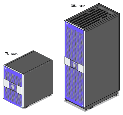
For most configurations, the visualization system is housed in one 17U rack or one 39U rack as shown in Figure 2-1; however, for small system configurations, the system modules can be placed on a table top.
Systems that are housed in 17U racks have a maximum weight of approximately 610 lb (277 kg). The maximum weight of systems that are housed in 39U racks is approximately 1,366 lb (620 kg). The racks have casters that enable you to remove the system from the shipping container and roll it to its placement at your site.
Check with your SGI service representative for additional physical planning information or documentation that may be available.
For more information about the technical specifications of your system and individual modules, see Appendix A, “Technical Specifications” in this manual.
The Silicon Graphics Prism is based on the SGI NUMAflex architecture, which is a shared-memory system architecture that is the basis of SGI HPC servers and supercomputers. The NUMAflex architecture is specifically engineered to provide technical professionals with superior performance and scalability in a design that is easy to deploy, program, and manage. It has the following features:
Shared access of processors, memory, and I/O. The Super Hub (SHub) ASICs and the NUMAlink interconnect functions of the NUMAflex architecture enable applications to share processors, memory, and I/O devices.
Each Super-Hub (SHUB) ASIC in the system acts as a memory controller between processors and memory for both local and remote memory references.
The NUMAlink interconnect channels information between all the modules in the system to create a single contiguous memory in the system of up to 192 GB and enables every processor in a system direct access to every I/O slot in the system.
Together, the SHub ASICs and the NUMAlink interconnect enable efficient access to processors, local and remote memory, and I/O devices without the bottlenecks associated with switches, backplanes, and other commodity interconnect technologies.
System scalability. The NUMAflex architecture incorporates a low-latency, high-bandwidth interconnect that is designed to maintain performance as you scale system computing, I/O, and storage functions. For example, the computing dimension in some system configurations can range from 4 to 16 processors in a single system image (SSI).
Efficient resource management. The NUMAflex architecture is designed to run complex models and, because the entire memory space is shared, large models can fit into memory with no programming restrictions. Rather than waiting for all of the processors to complete their assigned tasks, the system dynamically reallocates memory, resulting in faster time to solution.
A Silicon Graphics Prism system contains a combination of the following modules:
Base compute module. All Silicon Graphics Prism systems include at least one base compute module that contains the following components:
A node board with two Intel Itanium 2 processors (each processor has integrated L1, L2, and L3 caches), between 2 GB and 24 GB of local memory, and a SHUB ASIC (the crossbar between the processors, local memory, the network interface, and the I/O interface).
Four PCI/PCI–X slots
One four-port USB card that comes factory-installed in the top PCI/PCI–X slot
One IO10 PCI card that comes factory-installed in the lowermost PCI/PCI–X slot

Note: Each system or partition requires a minimum of base I/O card. The standard card providing this base I/O functionality is an IO10 PCI card. Additional IO10 cards are required if you want additional serial ATA hard drives and/or DVD-ROM drives in additional modules. These cards must reside in additional base compute modules (no more than one card per module). The IO10 card has real-time interrupt input and output ports, an Ethernet port, and a multi-port serial adapter connector. The IO10 card is also needed to support a base module's serial ATA disk drive(s), and DVD–ROM.
Note: The RT interrupt input and RT interrupt output functionality of the IO10 PCI card is not supported under SGI Linux + ProPack. A bootable hard drive
A DVD-ROM drive
XG2N graphics module. All systems contain at least one graphics module that has the following components:
A node board with zero or two Intel Itanium 2 processors (each processor has integrated L1, L2, and L3 caches), between 0 GB and 24 GB of local memory, and a SHUB ASIC (the crossbar between the processors, local memory, the network interface, and the I/O interface).
Two graphics pipes
CPU Expansion module. Like the base compute module, the CPU module contains a node board and local memory. This module is different from the base compute module, however, in the following ways:
It has zero, one, or two CPUs (the base compute module must have two CPUs)
It does not contain PCI/PCI-X slots, hard drives, or a removable media device.
CMPX module. Like the base compute module, the CMPX module contains a node board and local memory. This module is different from the base compute module, however, in the following ways:
It has zero, one, or two CPUs (the base compute module must have two CPUs)
It does not contain an IO10 PCI card, hard drives, or a removable media device.
Router module. The router module is an eight-port optional router that functions as a high-speed switch to route network packets between modules through the NUMAlink interconnect fabric.
When the system consists of a base compute module and XG2N graphics module only, it may contain a maximum of 4 processors and a maximum of 48 GB of memory. To increase the number of graphics pipes, processors, and/or memory in the system, the base compute module can connect to additional XG2N, CPU expansion and/or CMPX modules via direct NUMAlink or through router modules.
This section briefly describes the standard and optional modules of a Silicon Graphics Prism, in the following subsections:
The base compute module is a 2U AC-powered device that consists of the following:
Two Intel Itanium 2 processors (each with integrated L1, L2, and L3 caches)
Between 2 GB and 24 GB of local DIMM memory (4, 8, or 12 DIMMs)
One to four PCI/PCI–X cards
Note: At least one base compute module comes factory-installed with a base I/O card in the bottom PCI/PCI-X slot and a four-port USB card in the upper slot. This base I/O card is typically an IO10 card, but may optionally be an IO9 card (described in “Optional IO9 PCI Card ”). One or two sled-mounted serial ATA disk drives (at least one disk drive is required in the system). The serial ATA disk drive(s) and the DVD-ROM require an IO10 card.
DVD-ROM
Each base compute module also contains an L1 controller that provides the following:
Controls and sequences power
Controls and monitors the environment
Initiates a reset
Stores identification and configuration information
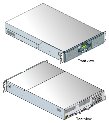
Figure 2-2 shows the front and rear views of a base compute module.
The XG2N graphics module (see Figure 2-3) is a 2U AC-powered device that consists of the following:
Two graphics pipes
Zero or two Intel Itanium 2 processors (each with integrated L1, L2, and L3 caches)
Between 0 GB and 24 GB of local DIMM memory (4, 8, or 12 DIMMs)
One L1 controller that provides the following services:
The CPU expansion module is a 2U AC-powered device that consists of the following:
Zero, one, or two Intel Itanium 2 processors (each with integrated L1, L2, and L3 caches)
Between 2 GB and 24 GB of local DIMM memory (4, 8, or 12 DIMMs)
One L1 controller that provides the following services:
Controls and sequences power
Controls and monitors the environment
Initiates a reset
Stores identification and configuration information
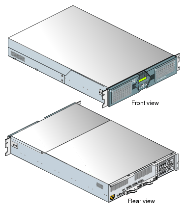
Figure 2-4 shows the front and rear views of a CPU expansion module.
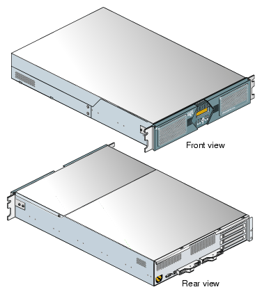
The CMPX module (see Figure 2-5) is a 2U AC-powered module that offers:
Zero, one, or two Intel Itanium 2 processors (each with integrated L1, L2, and L3 caches)
Between 2 and 24 GB of local DIMM memory (4, 8, or 12 DIMMs)
Four PCI/PCI-X slots
One L1 controller that provides the following services:
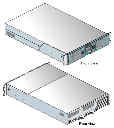
The optional router module (sometimes called an R-brick) is an eight-port 2U-high module that functions as a high-speed switch to route network packets between base compute, XG2N, CPU expansion, and CMPX modules. This creates a NUMAlink-4 interconnect fabric (as opposed to the ring topology normally used in smaller system configurations). The optional router is generally only used when there are four and eight modules interconnected as a single system image.
The section “NUMAlink Cabling in Routed Systems” in Chapter 3 details the cable connection points used in a system with a router.
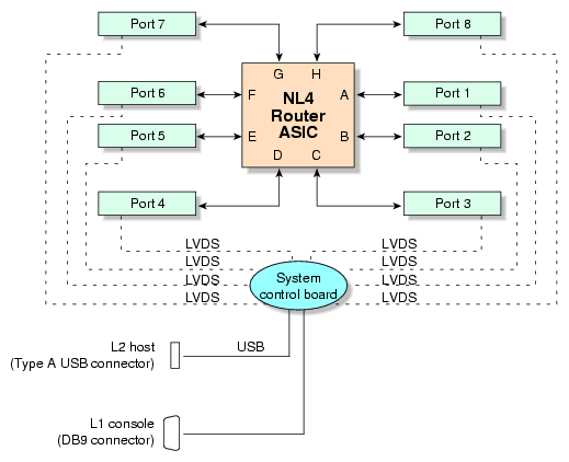
The key component within the module is the router chip, an SGI custom-designed ASIC. The router chip is an eight-port crossbar that connects any input-link channel to any of the seven possible output-link channels (ports).
The router has the following features:
Eight NUMAlink-4 channels
One USB port for system controller support
One L1 controller and LCD display
One 9-pin console connector
Two hot-pluggable cooling fans (not customer replaceable)
Figure 2-6 shows a block diagram of the router.
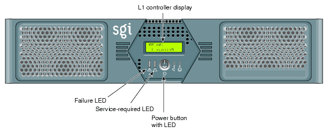
The router module contains the following front panel items (as shown in Figure 2-7):
L1 display. The L1 display is a 55.7 mm X 32 mm backlit liquid crystal display (LCD) that displays system messages. It displays two lines with a maximum of 12 characters on each line.
On/Off switch with LED. Press this button to turn on the router internal components. You can also turn on the router internal components at a system console.
Three LEDs:
Power-button LED. This green LED illuminates when the router internal components are on and turns off when they are off.
Service-required LED. This amber LED illuminates to indicate that an item is broken or not operating properly (for example, a fan is off), but the router is still operating.
Failure LED. This red LED illuminates to indicate that a system failure has occurred and the router is down.
Fans. Two hot-pluggable fans provide N+1 redundant cooling.
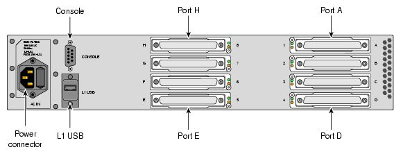
The router module has the following rear panel items (see Figure 2-8):
PWR (power) connector. This connects the router to the power outlet (120V or 220V, autosensing).
NUMAlink connectors. These NUMAlink connectors connect the router to the Prism compute or graphics modules to form an interconnect fabric.
L1 port connector. This connects the internal USB hub of the router to an optional console/controller. The internal USB hub can receive the USB signals from the controller via this port and distribute these signals to the L1 of the router.
Console connector. This serial port provides optional connection to a terminal for system control purposes.
Link connector LEDs. Each NUMAlink connector has two LEDs, as follows:
The yellow LED illuminates to indicate that both the router and the module to which this NUMAlink port is connected are powered on.
The green LED illuminates when a link has been established between the router and the module to which it is connected through this NUMAlink port.
A base compute module contains an IO10 base I/O card and two disk-drive bays. You can add additional storage to the system as follows:
For a SCSI (small computer system interface) JBOD (just a bunch of disks) solution, SGI offers the TP900 storage module. With the addition of an optional SCSI PCI card, the TP900 can be connected to base compute modules or CMPX expansion modules.
For a Fibre Channel solution that supports both JBOD and RAID configurations, SGI offers the 2Gb SGI TP9100 storage system.
The Silicon Graphics Prism also supports a number of tape devices; check with your SGI sales or support representative for available options.
The various storage devices are discussed in the subsections that follow.
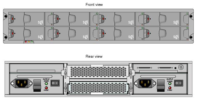
The TP900 storage module, shown in Figure 2-9, is a 2U-high 8-drive storage system that provides compact, high-capacity, high-availability JBOD storage. The enclosure backplane connects the 8 drives on one SCSI bus. As an option, the storage module can also be configured on two SCSI buses (2 strings of 4 drives).
This storage module has the following features:
It mounts in a standard 19-inch rack; it is available in factory-installed configurations.
It uses SCSI Parallel Interface 3 (SPI-3) capable Low Profile (1-inch high) 3.5-inch disk drives.
Its drive carriers accept SGI-qualified 10,000- or 15,000-RPM SCSI disk drives.
For more information about the TP900 storage module, see SGI Total Performance 900 Storage System User's Guide (007-4428-00x).
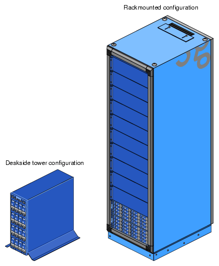
The 2Gb SGI TP9100, shown in Figure 2-10, is an affordable, entry-level RAID storage array that is easily expandable and comes in either a deskside tower or a rackmounted configuration. You can start with a basic JBOD configuration and later add RAID controllers, or you can start with a RAID configuration.
The 2Gb SGI TP9100 storage system connects to base compute and/or CMPX modules via an optional Fibre Channel PCI card. For more information about the SGI TP9100 storage system, see SGI Total Performance 9100 (2 Gb TP9100) Storage System User's Guide (007-4522-00x).
The Silicon Graphics Prism platform can contain the following power components:
One or two power distribution units ( PDUs). The second PDU is added to the system only when more than 10 AC power receptacles are needed within the rack.
The PDU inputs AC voltage from an external power receptacle and it can output AC voltage to the base compute modules, XG2N graphics modules, CPU expansion modules, CMPX modules, router modules, and TP900 storage modules.
See Figure 1-9 for an example.
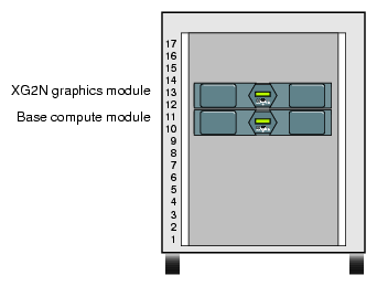
The system is offered in two rack types: a short rack and a tall rack. The racks are measured in standard rack units (U); one U is equal to 1.75 in. (4.45 cm). The short rack is a 17U rack (see Figure 2-11). The tall rack is a 39U rack (see Figure 2-14).
Each component within the rack is identified by the lowest U number that it occupies. For example, the top (XG2N) module shown in Figure 2-11 is described as being located in U12.
Both rack types are industry-standard 19-inch racks, and they support two types of mounting rails (shelf rails or optional slide rails) that hold the modules within the rack. For example, the base compute, XG2N, CPU expansion, and CMPX modules can use shelf rails or optional slide-mounting rails (see Figure 2-12). The optional TP900 storage modules always use shelf rails, which are two parallel L-shaped mounting rails within the rack (see Figure 2-13).
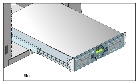
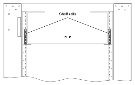
Both short and tall racks, as shown in Figure 2-14, have front and rear doors that have keylocks to prevent unauthorized access to the system. The racks also have cable entry/exit areas at the bottom of the racks. The 39U racks have cable management hardware in the rear.
Both rack types are mounted on four casters, two of which are swivel casters. The casters enable the rack to be rolled out of a shipping crate and to its placement at your site.
 | Warning: Follow the guidelines in “Safety Measures” in Chapter 1 and Appendix C, “Installing Rack Systems” to avoid damage to equipment, injury, or death. |
The base of each rack has seismic tie-down attachment points. The base of the tall rack also has leveling pads.
This section describes some of the optional devices available for the Silicon Graphics Prism system, in the following subsections:
If you do not wish to use the IO10 base I/O card in your system, an optional IO9 PCI card is required for base I/O functionality. Each system must contain at least one base I/O PCI card for base I/O functionality within the system. This PCI card must reside in bus 1, slot 1 (the bottom slot) of the lowest base compute module in the system. The IO9 PCI card has the following connectors:
External VHDCI 68-pin SCSI connector
10/100/1000BaseT Ethernet connector
Real-time interrupt output (RTO) and real-time interrupt input (RTI) connectors
Note: The RT interrupt input and RT interrupt output functionality of the IO9 PCI card is not supported under SGI Linux + ProPack.
The optional IO9 card also contains an IOC-4 ASIC that supports the following features:
One IDE channel for the DVD-ROM
NVRAM and time-of-day clock
The Silicon Graphics Prism supports optional or third-party tape drives. For current tape solutions for your system visit:
http://sales.corp.sgi.com/products/storage/tape.html
or check with your SGI sales or service representative.
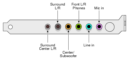
The DM8 is a half-size PCI expansion board that provides audio expansion via the PCI bus. It connects to consumer and professional audio and video equipment via industry-standard interfaces. Note that not all connector functionality is supported under Linux. The DM8 interface panel is shown in Figure 2-15.
Your DM8 audio board is tested for operation in specific SGI visualization systems. Select SGI Linux based systems support use of a single DM8 audio board (check with your SGI sales or support representative for functional confirmation). It is recommended that it not be removed and installed in other SGI systems.
SGI Linux based visualization systems support only one DM8 option board. Under most circumstances you should always leave the DM8 installed in the original factory-configured slot. If it does become necessary to either move or replace the board, use the information on removing and replacing PCI cards in your system user's guide for step-by-step instructions. If you don't have the printed user guide handy, it is available on the Internet in the SGI Technical Publications Library at the following location:
http://docs.sgi.com
Proceed to the next sections for information on cabling, verifying functionality, and basic operation.
The DM8 audio board has the following connectors on it's rear panel as shown from left to right in Figure 2-15:
Surround Center L/R (silver) a line-level output connector for powered surround Center Left and Right channel speakers (not supported under Linux).
Surround L/R (black) a line-level output that can connect to powered Surround Left and Right speakers (not supported under Linux).
Center/Subwoofer (orange) a line-level output that can connect to powered Center and Subwoofer speakers (not supported under Linux).
Front L/R Phones (green) a jack that connects to powered Left and Right speakers. If you are using a basic two-speaker stereo setup, this is the jack you will use. This is also the jack to use for stereo headphones.
Line In (blue) a stereo line-level input intended for recording into an audio recording program.
Mic In (pink) a mic input for connecting a mono microphone for recording, videophone, or voice-recognition applications. This jack is a three-conductor TRS-type jack for condenser (two-conductor) and electret (three-conductor) type microphones.
The DM8 PCI audio board has the following functional features:
| Line outs: |
Dynamic range of 106 dB (typical, -60 dB input, a-weighted)
Maximum line output level of 1.26 Vrms (+2 dBV)
Frequency response of +0.8/-3.0 dB, 20Hz to 80 kHz
| Line in: |
Dynamic range of 105 dB (a-weighted)
| Mic in: |
Dynamic range of 90 dB (a-weighted)
Maximum input level of 1.45 Vrms (3.2 dBV)
| Sampling frequencies (in kHz): |
Supports sampling frequencies 8, 11.025 16, 22.05, 32, 44.1, or 48kHz
| Audio playback formats: |
Output formats supported are:
24-bit linear PCM/48kHz playback capability for Linux systems
24-bit linear PCM/48kHz recording capability for Linux systems
| Connector features: |
Analog connector for powered speakers (headphone jack)
Stereo 1/8-inch mini analog line input
Mono 1/8-inch mini analog microphone input (with electret mic power)
Use the following information to help correct any functional problems with the DM8 audio PCI option board:
If the sound is distorted or a channel is not producing sound, try the following:
Check all cable connections between the audio card and speakers
Confirm that any powered speakers are powered on
If the audio is not working at all, try these solutions:
Reboot the system
Reseat the PCI audio card
If none of these solutions solve the problem, contact your SGI customer support representative or local service provider for additional help.
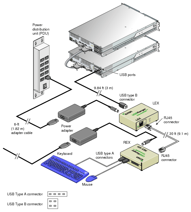
You can plug the keyboard and mouse directly into the USB connectors of a compute module (see “Connecting a Keyboard and Mouse” in Chapter 1), or you can use an optional USB extender that allows you to place the keyboard and mouse up to 328.68 feet (100 m) from the compute module, see Figure 2-16.
| Note: The local extender (LEX) receives AC power from the system power source or power distribution strip (PDS) in the rack. A 6-ft. (1.82-m) adapter cable connects the extender's power adapter to the PDU. The REX requires AC power from a source within a 6-ft. (1.82-m) range from the keyboard/mouse connection point. |