Chapter 2, “Getting Started” provides an overview of the basic concepts of OpenGL Volumizer. This chapter describes in greater detail how you use the OpenGL Volumizer API. For details on the individual classes, refer to their respective man pages.
This chapter has the following sections:
Table 3-1 summarizes the base classes for all the OpenGL Volumizer object classes.
The following subsections describe the roles of these classes:
All OpenGL Volumizer object classes are derived from the base class vzMemory. It provides you with the ability to control memory allocation and deallocation of objects by providing two static operators new and delete. By default, the operators new and delete simply use the malloc() and free() functions. By overriding this default behavior, you can customize the allocation and deallocation of OpenGL Volumizer objects.
For example, consider the case of designing a volume rendering application using OpenGL Performer where OpenGL Volumizer shape nodes are used to represent the volumetric components of the scene. OpenGL Performer uses a multiprocess model of execution, using the fork() system call to set up separate processes for APP, CULL, and DRAW. To share the objects between the processes, you would need to allocate them in shared memory. To accomplish this, simply override the default new and delete operators by setting two callback functions: one for allocation and one for deallocation.
For instance, the following lines force the API to use OpenGL Performer shared arenas:
// Set the callbacks for vzMemory base class vzMemory::setMemoryManagementCallbacks (myNewCB, myDeleteCB, NULL); |
The callbacks myNewCB() and myDeleteCB() look like the following:
// Callback for memory allocation - uses pfMalloc()
void *myNewCB (size_t nBytes, void *userData) {
   return pfMalloc (nBytes, pfGetSharedArena());
}

// Callback for freeing memory - uses pfFree()
void myDeleteCB (void *ptr, void *userData) {
   pfFree (ptr);
}
|
Any subsequent calls to vzMemory:: malloc() and vzMemory:: free() will use the callbacks specified above to allocate and de-allocate memory, respectively. All application data that needs to be shared across processes in the preceding case should be allocated using these methods. Refer to the vzMemory man page for details of the functions used in the preceding code.
The vzObject class encapsulates the notions of reference counting and deletion notification, which this section describes separately.
Reference counting allows painless memory management of objects that are shared between multiple objects. The basic idea is to maintain a counter for each object to indicate the number of outside references currently being held for it. Thus, the counter value indicates the number of users and objects that have a reference for the object. A count of zero indicates that there are no references to the object and, hence, it is safe to delete it.
All OpenGL Volumizer objects are derived from the vzObject class, which provides simple reference counting and deletion notification facilities. When an object is created, its reference count is initialized to one. If the reference count of an object reaches zero, the object calls its own destructor.
The vzObject class provides two public methods: ref() and unref(), which can be used to increase and decrease the reference count for the object, respectively. For each invocation of ref(), the count is increased by one and similarly for unref(), the count is decreased by one. If inside an unref() call the counter reaches zero, the object deletes itself.
The following code snippet from the example used in “Sample Volume Rendering Application” in Chapter 2 illustrates the use of reference counts for the shader.
// shader ref count = 1 vzShader *shader = new vzTMSimpleShader(); // shader ref count = 2 vzAppearance *appearance = new vzAppearance(shader); // shader ref count = 1 shader->unref(); |
The shader is unreferenced since the appearance would invoke a ref() on it inside the constructor. Unreferencing the shader ensures that it would get deleted when the appearance is deleted. This is because, in its destructor, the appearance would invoke an unref() on the shader, which brings its reference count to 0, hence, deleting it. The following code illustrates the use of reference counts for the geometry and appearance classes.
// geometry ref count = 1 vzGeometry *geometry = new vzBlock(); // geometry ref count = 2, appearance ref count = 2 shape = new vzShape(geometry, appearance); // geometry ref count = 1 geometry->unref(); // appearance ref count = 1 appearance->unref(); |
If you are not careful, you might make mistakes with the reference counting system. Two possible symptoms result from mismanagement of reference counts:
Your program leaks memory. This is caused by forgetting to use unref() on an object once you are done using it.
You have called methods on objects that have already been deleted. Once an object's reference count drops to zero, it is invalid to call methods on it. Doing so will have unpredictable results.
The OpenGL Volumizer API in itself is very consistent with the use of reference counts—that is, every object A that keeps a reference for another object B invokes a ref() on B. Also, A is supposed to invoke an unref() on B when it removes that reference. If you were to create a new geometry and use it for the shape node in the sample application from “Sample Volume Rendering Application” in Chapter 2, you would do something like the following:
// create a new geometry vzGeometry *newGeometry = createNewGeometry(); // update the geometry for the shape to the new one shape->setGeometry(newGeometry); |
The following steps occur inside the setGeometry() method of vzShape:
void setGeometry(vzGeometry *newGeometry) {

    // ref() the new geometry
    newGeometry->ref();

    // unref() the old geometry
    currentGeometry->unref();

    // update the geometry
    currentGeometry = newGeometry;
}
|
To debug reference counts more effectively, you can set the debug level to 4 (see the vzError class for details). This causes the API to print the value of the reference count every time a ref() or unref() call is issued.
The OpenGL Volumizer API maintains a consistent system for memory allocation and deallocation. If you allocate any memory, then it is your responsibility to free that chunk of memory. To do this, it is essential for you to know when an object is about to be deleted—that is, when its reference count drops to zero. The API provides you the ability to specify deletion callbacks that are invoked just before an object is deleted. These callbacks can be used to do the necessary cleanup for the particular object.
The following code illustrates the use of this deletion notification system for freeing memory. Suppose you allocated a floating point array of vertex data and passed a pointer into the vzVertexArray class as in the following:
int numVerts = 20; float *myData = new float[numVerts*3]; vzVertexArray *array = new vzVertexArray (numVerts, myData); |
Since you allocated the memory for the array, you are responsible for freeing it. Using the deletion notification system, this can be accomplished very easily by installing a deletion callback on the vertex array. This callback can be used to free the array since it is no longer needed, as shown in the following example:
// Add a deletion notification callback to the vertexArray just created
vertexArray->addDeletionCallback (myArrayDeletionCB, myData);

// Deletion notification callback - frees allocated memory
void myArrayDeletionCB (vzObject *object, void *userData) {
   delete [] userData;
}
|
It is valid to add multiple deletion callbacks with the same function pointer but different user data pointers. Refer to the vzObject man page for details of the callbacks and functions used in this section.
Table 3-2 summarizes the shape-related classes.
Table 3-2. Shape-Related Classes
Class | Description |
|---|---|
Container node for a volume's geometry and appearance | |
Geometry of a shape node | |
Volumetric geometry associated with a shape node | |
Volumetric geometry representing an axis-aligned cuboid | |
Volumetric geometry representing a structured hexahedral mesh | |
Unstructured volumetric geometry | |
Volumetric geometry representing an unstructured tetrahedral mesh | |
Volumetric geometry representing an unstructured hexahedral mesh | |
An array of floating-point vertex coordinates | |
An array of integral indexes | |
Appearance description of a shape node | |
Shader parameter for a shape's appearance | |
A set of slice planes |
This section describes how to use the shape-related classes in the following subsections:
As mentioned briefly in Chapter 2, “Getting Started”, the shape node encapsulates a volumetric representation in the form of its geometry and appearance. The shape node is the basic unit of rendering in the OpenGL Volumizer API. This means that the shape node is atomic; hence, you cannot render part of a shape. Shape nodes form the leaf nodes of a potentially more complex scene graph. The scene graph can be built upon the existing infrastructure provided by OpenGL Volumizer.
The geometry of a shape provides a region of interest while the appearance controls how it looks. In other words, the geometry of the shape describes what is rendered and the appearance describes how the geometry is rendered. Figure 3-1 illustrates this separation.

As mentioned before, the geometry of a shape defines what is rendered or the spatial attributes of the shape. In general, geometry can have any dimension. For example, a triangle is a 2D geometry type whereas a tetrahedron is 3D.
2D objects can be directly rendered using OpenGL primitives like triangles and polygons while 3D objects cannot. In order to render 3D objects using OpenGL, you must generate 2D primitives first and then use them to render the 3D objects.
The vzGeometry class is an abstract class which can be used to represent the geometry associated with a shape node. The class has one public method that allows you to retrieve the bounding box of the geometry. You can use the bounding box, which is an attribute of every geometric object, for culling to the viewing frustum, collision detection, or applying other special algorithms.
This following subsections further describe how to define your geometry:
OpenGL Volumizer allows you to specify 3D geometry using the vzVolumeGeometry class, which is derived from the vzGeometry class. The vzVolumeGeometry class can be used to represent a set of polyhedral primitives that define the volumetric structure of the shape node. On one hand, OpenGL Volumizer simplifies the description for the most commonly used cases of volumetric geometry like cuboids. On the other hand, it provides other constructs to allow specifying much more complex geometry types like structured hexahedral meshes and unstructured tetrahedral meshes. This is done by providing built-in classes that support these representations. For a complete list of the built-in volumetric geometry classes, see Table 3-2.
All volumetric geometry types can be represented using a set of tetrahedra. Hence, internally OpenGL Volumizer uses the tetrahedron as the basic unit for representing volumetric geometry. The volumetric geometry class that represents arbitrary tetrahedral meshes is vzUnstructuredTetraMesh, which is described later in section “General Tetrahedral Meshes”. All of the classes derived from the vzVolumeGeometry class need to know how to tessellate themselves into such a tetrahedal mesh. The following subsections describe the two most important volumetric geometry classes, vzBlock and vzUnstructuredTetraMesh. For a description of the others, refer to the man pages of the classes listed in Table 3-2.
In addition to specifying the volumetric geometry, the vzVolumeGeometry class allows you to set arbitrary slice planes that pass through it. In many volume rendering applications, slice planes passing through the volume data can be a very powerful visualization technique. See the vzSlicePlaneSet man page for more details on how to use these slice planes in conjunction with volumetric geometry.
The vzBlock class is used to represent the simple case of an axis-aligned cuboid. This is the simplest and the most commonly used construct used to represent volumetric data. The vzBlock class has routines that allow you to set the offsets and dimensions of this cuboid.
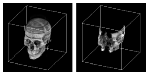
The sample application “Sample Volume Rendering Application” in Chapter 2 uses a vzBlock object to represent the geometry of the volume data. By default, the constructor creates a cuboid at the offsets (0, 0, 0) and with dimensions (1, 1, 1). Try adding the following lines of code to the application before the renderAction->beginDraw() line:
// New offset and dimensions
float offset[3] = {0.25,0.25,0.25}, dimensions[3] = {0.5,0.5,0.5};

// Shape's geometry
vzBlock *block = (vzBlock *) shape->getGeometry();

// Modify the offsets for the cuboid
block->setOffsets(offset);

// Modify the dimensions of the cuboid
block->setDimensions(dimensions);
|
The result should be similar to the one shown in Figure 3-2. This simple example illustrates how modifying the geometry can allow you to carve your shape node.
The vzUnstructuredTetraMesh class is derived from the vzUnstructuredMesh class and represents indexed sets of tetrahedra. Each tetrahedron is represented by four integers that index a list of vertex coordinates. Figure 3-3 illustrates the structure of an unstructured tetrahedral mesh.
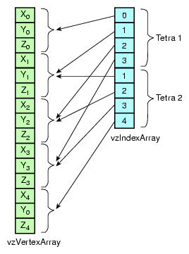
For example, you can represent an octahedron using a tetrahedral mesh consisting of six vertices and four tetrahedra.
It is possible to derive your own subclass of volumetric geometry simply by overriding the virtual tessellate() method of a vzVolumeGeometry object.
The tessellate() method is intended to take your geometry type and tessellate it into tetrahedra, which can then be used as geometry by the render actions. For example, you could design a vzSphere class that knew how to tessellate itself into tetrahedra. Simply create and initialize a vzIndexArray object and a vzVertexArray object for the resulting tetrahedral-mesh approximation.
In addition to the basic geometry elements outlined earlier in this section, OpenGL Volumizer allows applications to use arbitrary polygonal geometry within a shape node. The vzPolyGeometry class and its associated virtual draw method provides a vehicle for such implementations.
The vzPolyGeometry class represents any polygonal geometry attached to a shape node. Derived from the vzGeometry abstract class, the class provides a pure virtual draw method, invoked by the render action while rendering the shape node. When the render action invokes the draw method, it passes the appropriate bounding box of the polygonal geometry to be rendered.This method allows applications to skip the "polygonization" step of the render action and instead, render arbitrary polygonal geometry. The OpenGL state used is the same as for the render action with polygonized geometry. The example below illustrates how to use this class:
class myPolyGeometry: public vzPolyGeometry {
public:
       virtual void draw(double bounding_box[6]) const
       {
          // Render geometry
       }
};
|
The vzAppearance class encodes the visual attributes of a shape node. Volumetric appearance includes all descriptive characteristics that control the way a volumetric shape will look when it is rendered. The render actions are responsible for interpreting and applying this appearance description during the rendering process.
The appearance contains a list of parameters and a shader. Shaders associated with an appearance are specific to the render action to be applied to the shape. The list of parameters are attributes that are used by the shader to generate a desired visual effect. The appearance associates each parameter attached to it with a name and type.
Each render action supports one or more built-in shaders. Each shader in turn expects parameters of a given name and type, which are necessary for its use. For example, the sample application “Sample Volume Rendering Application” in Chapter 2 creates a simple appearance that uses the shader vzTMSimpleShader to volume render the given shape using 3D texture mapping.
TMRenderAction, used in the sample application, supports another built-in shader called vzTMTangentSpaceShader, which expects three parameters (see Chapter 4, “Texture Mapping Render Action” for more details). The following code creates the appearance to be used to perform gradient-less shading of volumetric data:
// Create a tangent space shader vzTMTangentSpaceShader *shader = new vzTMTangentSpaceShader(); // Create the appearance vzAppearance *appearance = new vzAppearance(shader); // Set the parameters required by the shader appearance->setParameter (“volume”, volumeTextureParameter); appearance->setParameter (“lookup_table”, lookupTableParameter); appearance->setParameter (“lightdir”, lightDirectionParameter); |
The appearance stores a reference to the supplied parameters and associates them with the given names. Invoking the setParameter() method with a name already used but with a different parameter would overwrite the previous value.
Parameters are attached to the shape's appearance and provide the necessary information to complete a volumetric appearance description. Examples of parameters include 3D textures, texture lookup tables, lighting directions, and per-vertex floating point values.
The vzParameter class forms an abstract base class for all the shader parameters. For complete descriptions of the parameter classes and their usage, see Chapter 4, “Texture Mapping Render Action” and Chapter 7, “Irregular Grids: The Projected Tetrahedra Render Action”.
Table 3-3 summarizes the function of the rendering classes.
Class | Description |
|---|---|
Renderer for drawing shape nodes | |
Shader for generating a desired visual effect from an appearance |
This section describes the use of the two classes listed in Table 3-3.
A render action, as mentioned earlier, implements a certain visualization algorithm to render the given shape nodes. Depending on the available resources and desired effect, you can apply different render actions to render your volume data. For example, TMRenderAction shipped with OpenGL Volumizer renders shape nodes using 3D texture mapping. You can also write your render action to implement different visualization algorithms if you want.
Render actions are responsible for more than just implementing a particular visualization algorithm. They can also perform the resource management for improving the performance of the rendering. This might also include doing their own OpenGL state management.
In order for a render action to implement intelligent resource management techniques, it should have some knowledge of the total size of resources available on the system and what is required to render the given shape nodes. You can provide information about the latter using the manage() and unmanage() methods of the render action. You can add a shape to the render action's list of managed shapes using manage() and remove it using unmanage(). Finally, the shapes can be drawn by calling draw() on the shapes. A shape that has not been managed cannot be drawn, but a shape that has been managed does not need to be drawn. Refer to the documentation specific to the render action you are using for the details on its implementation.
Each render action recognizes a certain set of built-in shaders. Each built-in shader expects certain parameters to be defined. You must provide all of the parameters required for a given shader; failing to do so will generate an error. Shaders extract the required parameters from the respective appearances using the getParameter() method with the name of the respective parameters as an argument. For information on the built-in shaders available for the render action, see the documentation specific to the render action you are using.
Shaders are more lightweight as opposed to render actions in the sense that they are only concerned with the specific OpenGL state settings required to generate a particular visual effect. On the other hand, the render action performs more complex resource management for the list of shapes that are managed and need to be rendered. Hence, switching the shader for an appearance by using the setShader() method of the vzAppearance class would have minimal overhead. But using a different render action would involve more complex resource management to be done for the shape.
The vzError class implements a mechanism for logging and reporting errors. It can also be used to print debug messages at run time. The class consists of a collection of static methods that allow you to do the error processing.
The following two subsections describe error processing:
The vzError::log() method is used by the library to log errors. Depending on the severity of the error (see vzErrorSeverity), you can issue a log() call with a severity of VZ_ERROR or VZ_WARNING. You can use your own error routine to handle all the logged errors. The default handler simply prints out an error message if the severity is VZ_WARNING. If the severity is VZ_ERROR, it calls abort() after printing the error message. The error handler installed applies to all threads.
You can use the convenience methods error() and warn() to log errors and warnings, respectively. Calling error() or warn() is equivalent to calling log() with the severity passed in as VZ_ERROR or VZ_WARNING.
The following example shows how to install your own error handling routine.
// Set the error handler for vzError::log() vzError::setHandler (myHandler, NULL); |
The handler might look like the following:
static void myHandler(vzErrorSeverity severity, vzErrorType type,
                      const char *format, va_list args, void* data)
{
    if(severity == VZ_ERROR)
        cerr<<"myHandler::Error!!!";
    else if(severity == VZ_WARNING)
        cerr<<"myHandler::Warning!!!";

    // Print the error message
    vfprintf(stderr, format, args);

    // Use the vzErrorType to do whatever else is needed!!!
    ....
}
|
Regardless of the error handler in effect, the first error encountered will be recorded and can be queried later using getError(). The clear() method resets the saved error to VZ_NO_ERROR. Errors are recorded and cleared on a per-thread basis.
The vzError class also provides the message() method to print debug messages that are neither errors nor warnings. Each debug message is given a particular debug level, passed as a parameter to the message() method.
The message will be output to stderr only if the debug level of the message is less than or equal to the current debug level. Therefore, the higher you set this debug level, the more debug information you will see. This is useful for debugging reference counts, monitoring texture memory usage, and so on.
The API internally does not use messages of levels 0 or 1. The guidelines in Table 3-4 are used by the API to print debug messages.
Table 3-4. Guidelines for Debug Messages
To debug applications effectively, you can print out the right level of debug messages by setting the environment variable VOLUMIZER_DEBUG_LEVEL to the appropriate value.