The Texture Mapping Render Action ( TMRenderAction) is the standard render action provided by OpenGL Volumizer. This render action uses the 3D texture mapping hardware to perform volume rendering of the given shape nodes.
This chapter describes the following topics:
The main steps involved in volume rendering using 3D texture mapping are as follows:
Figure 4-1 depicts the previous steps, respectively:
Figure 4-1. Viewport-Aligned Sampling Planes, 3D Textures Sampling Planes, and Final Image after Back-to-Front Compositing
 |
The following are advantages of using 3D texture mapping:
Immediate-mode execution to prevent the overhead of storing transient geometry from polygonization.
Optimized texture managment for improved texture download performance. [This includes the case of texture memory oversubscription.]
Support for custom volumetric shading techniques along with built-in shaders for volumetric lighting and tagging.
Transparent bricking and interleaving of texture data.
Support for applications using multi-resolution and volume roaming techniques.
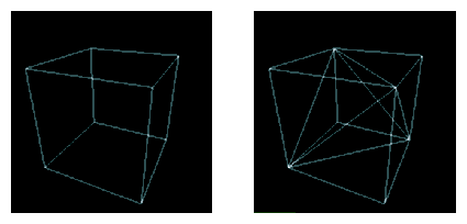
TMRenderAction implements a 3D volume rendering technique. The render action uses the tetrahedron as the basic unit for representing volumetric geometry. The rendering algorithm used by TMRenderAction consists of the following steps:
Tessellate the given volumetric geometry into a tetrahedral mesh.
Figure 4-2 depicts the tessellation.
Sort the tetrahedral mesh in a back-to-front visibility order.
Set the OpenGL state for a given shader.
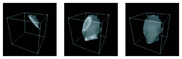
Starting with the rearmost element, slice the tetrahedra one-by-one and render the polygonal geometry generated.
Figure 4-3 illustrates the slicing and the final rendering.
The sample application in Chapter 2, “Getting Started” shows how simple it is to use the vzTMRenderAction class to render a simple volume shape. However, most real-life volume rendering applications need to do more complex operations than just render a simple volume shape. The vzTMRenderAction class has been designed with such applications in mind.
The following sections describe how to use the various components of TMRenderAction:
The constructor to the render action takes an integer as a parameter, which represents the maximum number of threads the render action is allowed to create, as shown in the following:
vzTMRenderAction (int maxThreads); |
The render action is not thread safe. Hence, do not share render actions across multiple threads. Also, for efficiency reasons, create only one render action per graphics pipe.
The vzTMRenderAction base class has the following pure virtual methods:
They allow the application to tell the render action about the shapes it wants to be cached and rendered. The process is shown in Figure 4-4.
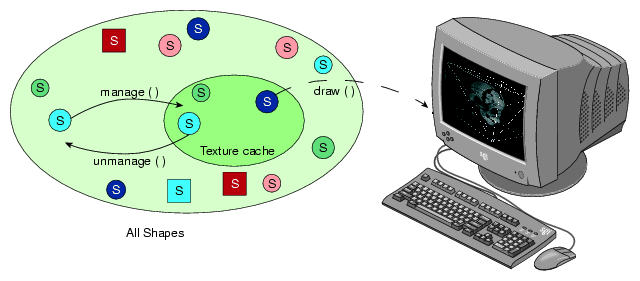
TMRenderAction tries to load all the managed shapes into texture memory. Similarily, it removes any unmanaged shapes from the texture memory. All shapes that are drawn need to be managed first, even though it is not necessary to draw all the shapes currently managed.
The beginDraw() and endDraw() methods are used to inform the render action about the end of the management phase and the beginning of the rendering phase. The render action performs all the texture management in the beginDraw() method. Hence, all the manage() and unmanage() calls are queued until the application issues a beginDraw() call, when the actual management is done.
TMRenderAction currently supports a number of built-in shaders. All of them use 3D texture mapping to do volume rendering and implement specific techniques to generate a desired visual effect. All shaders render the shapes using one or more passes over the polygonal geometry generated from the slicing of the volumetric geometry. As you might expect, there is one parameter common to all shaders supported by TMRenderAction: volume. This parameter specifies the actual volume data to be rendered and is of the type vzParameterVolumeTexture.
The following subsections describe the list of built-in shaders currently supported by TMRenderAction:
In addition to the built-in shaders, TMRenderAction also supports custom shaders. See Chapter 5, “Custom Volumetric Shading”.
The shader vzTMSimpleShader has the following parameter:
| Parameter Name | Type | |
| volume | vzParameterVolumeTexture |
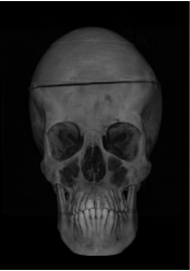
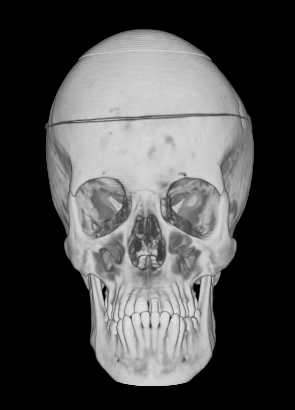
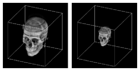
As the name implies, vzTMSimpleShader performs simple volume rendering of the given volume texture. The polygonal geometry to be rendered is generated as described earlier in section “Volume Rendering Using 3D Texture Mapping”. This geometry is rendered in a back-to-front order with the given "volume" texture as the currently bound texture. Figure 4-5 shows a 256 MB size CT of a human head rendered using vzTMSimpleShader.
The shader vzTMLUTShader has the two following parameters:
| Parameter Name | Type | |
| volume | vzParameterVolumeTexture | |
| lookup_table | vzParameterLookupTable |
The shader vzTMLUTShader allows you to apply transfer functions to the volume data by using a one-dimensional lookup table, which maps the interpolated texel values to color values. You can achieve a similar effect by applying the transfer function to precompute the color values for each texel in the volume and then use it as the volume texture for vzTMSimpleShader. This technique, however, would have a huge overhead due to the amount of computation involved. In addition, for every change to the transfer function the whole volume data will need to be re-downloaded to texture memory.
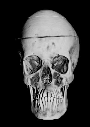
Using the OpenGL hardware, the shader vzTMLUTShader applies the transfer function in a system-dependent fashion. This process is much faster than doing the computation in software. Moreover, for every change to the transfer function, only the lookup table needs to be downloaded again, which is usually much faster than downloading the whole volume texture. Figure 4-6 shows the head data set used in Figure 4-5 now rendered with vzTMLUTShader. Notice how use of the LUT shader allows getting rid of unwanted values in the data set.
The shader vzTMTangentSpaceShader has the three following parameters:
| Parameter Name | Type | |
| volume | vzParameterVolumeTexture | |
| lookup_table | vzParameterLookupTable | |
| lightdir | vzParameterVec3f |
The shader vzTMTangentSpaceShader implements a shader to perform lighting of volumetric data. The shader also uses lookup tables to apply transfer functions to the volumetric data. In order to perform the lighting computations, the shader also expects a parameter to specify the direction of the light source. Figure 4-7 shows the head data set used in Figure 4-5 now rendered with vzTMTangentSpaceShader. Notice how use of the Tangent Space shader provides higher image quality and better depth cues.
The technique implemented by vzTMTangentSpaceShader is a gradient-less lighting technique. It does not use the gradients for every texel of the volume data. The lighting computations are performed by using an approximation to the diffuse lighting component of the Phong shading model.
| Note: The shader vzTMTangentSpaceShader does not generate correct lighting of volumetric data. It simply creates the appropriate visual effect by using a system-dependent technique. The technique used here produces seams for bricked shapes along the borders of the bricks (see the later section “Texture Management” for more information on bricks). Use vzTMGradientShader for correct volumetric lighting of shapes. |
| Note: This shader is not available in versions prior to OpenGL Volumizer 2.1. |
The shader vzTMGradientShader has the following parameters:
| Parameter Name | Type | |
| volume | vzParameterVolumeTexture | |
| gradient | vzParameterVolumeTexture | |
| lightdir | vzParameterVec3f | |
| lookup_table | vzParameterLookupTable | |
| ambient | vzParameterVec3f (optional) | |
| diffuse | vzParameterVec3f (optional) | |
| specular | vzParameterVec3f (optional) | |
| shininess | vzParameterVec3f (optional) |
The shader vzTMGradientShader is a cross-platform shader that implements volumetric shading based on the Phong illumination model. The actual implementation used by the shader is platform-dependent. The shader uses per-voxel gradient information in order to compute the contributions from diffuse and specular coefficients to the output color. This gradient information can be specified as a parameter to the shape's appearance. In this case, the parameter volume defines the actual volume data, while the parameter gradient defines the corresponding gradient values. The RGB values of gradient provide the (a, b, c) coefficients for the gradient at the corresponding voxel in volume. The application must compute the gradient texture and add it to the shape's appearance.
Relative to the vzTMTangentSpaceShader, the use of a separate gradient texture generates more accurate lighting effects and does not have the artifacts associated with the bricking of shapes. However, this can potentially increase the texture memory usage by a factor of two to four times the size of the original volume texture.
Non-GPU-Based Systems
On systems which do not support the ARB_fragment_program OpenGL extension, the parameters specular and shininess do not have any effect.
On systems which do not support ARB_ fragment_program or the ATI_fragment_shader OpenGL extensions, the shading algorithm uses the destination alpha to compute the gradient lighting. Hence, the application should make sure that the appropriate visual is selected. In this case, the system should support ARB_imaging extensions and the gradient texture should have an internal texture format of VZ_INTENSITYn, where n can 8, 12, or 16. The shader accepts a lookup table parameter to apply transfer functions to the volume data.
GPU-Based Systems
On GPU-based systems like Silicon Graphics Prism systems that support the ARB_fragment_program extension, if parameter gradient is not specified, the shader computes the gradient values internally using central differencing.
| Note: This shader is not available in versions prior to OpenGL Volumizer 2.1. |
The shader vzTMTagShader has the following three parameters:
| Parameter Name | Type | |
| volume | vzParameterVolumeTexture | |
| tag | vzParameterVolumeTexture | |
| lookup_table | vzParameterLookupTable |
The vzTMTagShader implements system-dependent techniques to perform volumetric tagging. The algorithm uses two perfectly overlapping volumes. The volume texture defines the actual volume data, while the tag texture defines a 3D stencil buffer for volume. Each value in tag contains the mask for the corresponding texel in volume. If the value of the tag texel is greater than 0.5, then the corresponding texel in the volume data is rendered; otherwise, the texel is masked out. Figure 4-8 shows the head data set used in Figure 4-5 now rendered with vzTMTagShader. Notice how use of the vzTag Shader allows masking out arbitrary regions in the data set.
The vzTMTagShader uses a system-dependent technique to perform tagging. Ideally, the tag volume should require only one bit to represent each texel. However, on most graphics hardware, each texel will use at least one byte to represent a texel.
Notes:
On systems that do not support the ARB_fragment_program or ATI_fragment_shader OpenGL extensions, the vzTMTagShader uses the stencil buffer to implement the tagging algorithm. Hence, the application should ensure that the appropriate visual is selected.
Using vzTMTagShader has the overhead of storing an additional 3D texture in the texture memory. You can also generate the same effect by actually modifying the volume texture to remove the unwanted texels by setting their opacity to zero explicitly. This, however, has the disadvantage of modifying the original volume data.
The preceding section describes the list of shaders that are supported by TMRenderAction. The following subsections briefly describe the shader parameters used by the shaders:
For details on the specific methods, refer to the man pages of the individual classes.
The vzParameterVolumeTexture class provides a simple abstraction of a 3D texture and its position in 3D space. This section describes each of the components of the class by looking at the constructor for the class. The following is the constructor:
vzParameterVolumeTexture( const int dataDimensions[3],
                        const int dataROI[6],
                        void* dataPtr,
                        vzTextureType dataType,
                        vzExternalTextureFormat externalFormat,
                        vzInternalTextureFormatinternalFormat=
                        VZ_DEFAULT_INTERNAL_FORMAT);
|
The dataDimensions values are the dimensions of the texture data along the X, Y, and Z axes, respectively. The dataROI value specifies a cuboidal region of interest ( ROI) “contained” within the volumetric data. This will be useful if, for example, you have a volumetric data of size 256 x 256 x 256 and you want to render texture data of size 128 x 128 x 128 starting at offsets (64, 64, 64). This can be done simply by choosing a dataROI defined as in the following:
int dataROI[6] = {64, 64, 64, 191, 191, 191};
|
This prevents you from having to create a separate buffer for the subtexture and then copying the data over to it. TMRenderAction will use only the data that lies in the data ROI for all subsequent operations.
The dataPtr value specifies the actual texture data. The dataType value specifies the type of the texture data stored in the dataPtr variable (unsigned byte, integer, float, etc.), while the externalFormat value specifies the format of the data (luminance, RGBA, etc.). One can also specify the internal format to be used for the OpenGL texture. The internal format is the format used internally by OpenGL to store the texture in texture memory. The texture data has to be specified in a row-major order, as when creating a 3D texture in OpenGL using the glTexImage3D() function call. For example, if the external format is RGBA, the data should be stored as in the following:
{ {R1, G1, B1, A1}, {R2, G2, B2, A2}, .....}
|
Note the following:
The texture data is only “shallow copied” by the API. This means that there is no allocation done internally for the texture data. The class just stores the data pointer and uses it for all subsequent operations.
The texture data can be modified by using the setDataPtr() method. This call would force TMRenderAction to reload the texture into texture memory before using the texture again.
The dataDimensions, dataROI, dataType, externalFormat, and internalFormat values of a texture cannot be modified once the texture has been created. In order to change any of the above, you will need to create a new texture and use the setParameter() method of the shape's appearance to use the new texture.
The texture dimensions do not need to be powers of two as required by OpenGL. TMRenderAction will internally pad the texture data to create the appropriate power-of-two texture.
The complete texture need not fit in texture memory. If the texture does not fit in texture memory, TMRenderAction will break the texture into smaller bricks internally and use them to create the actual OpenGL textures.
If a default value is used for the internal format, then the render action would infer a suitable value from the data type and external format of the texture.
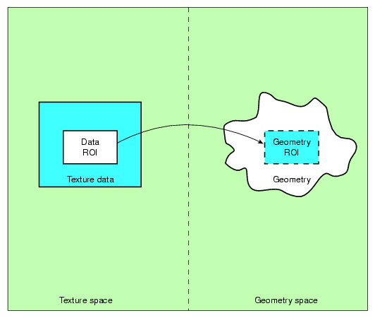
In addition to specifying the texture data for the 3D texture, the vzParameterVolumeTexture class also contains information for mapping the texture data to geometry space. This mapping is specified by the geometryROI parameter of the volume texture. The geometry ROI of the texture represents the bounding box for the region in world space to which the texture maps. Figure 4-9 illustrates the relationship between the data ROI and the geometry ROI of a texture.
The geometry lying outside the geometry ROI is clipped out by TMRenderAction using clipping planes. If a particular OpenGL clipping plane is enabled before calling the draw() method, then TMRenderAction uses software clipping planes to clip the geometry. Otherwise, it uses OpenGL clipping planes to do the clipping. This allows you to use OpenGL clipping planes in your application. The values for the geometry ROI are set to (0, 0, 0) to (1, 1, 1) by default inside the constructor. Try adding the following lines of code to the sample program in Chapter 2, “Getting Started”:
// Get the parameter “volume” from the shape's appearance
vzParameter *parameter =shape->getAppearance()->getParameter(“volume”);

// Cast the parameter to a vzParameterVolumeTexture
vzParameterVolumeTexture *texture =
                                  (vzParameterVolumeTexture*)parameter;

// Set the geometryROI for the texture
double geometryROI[6] = {0.25, 0.25, 0.25, 0.75, 0.75, 0.75};
texture->setGeometryROI(geometryROI);
|
Figure 4-10 shows the original texture and the modified texture. This illustrates how you can arbitrarily scale and translate your texture to fit the shape's geometry.
Note the following:
If specified, only the data ROI gets mapped to the geometry ROI and not the entire texture.
The voxel samples along the border of the data ROI are mapped so that they lie exactly along the boundaries of the geometry ROI.
The vzParameterLookupTable class provides a mechanism for specifying transfer functions to be applied to the volume texture. A transfer function provides the mapping from data values to color values. In this case, it provides the mapping from texel values in the volume texture to color values to be rendered. Using transfer functions, you can visually “remove” unwanted values from the volume rendered image by setting an alpha value of zero for such values. Similarly, you can emphasize other values by giving them different colors and high opacity values. This could be used, for example, to see only the skull from the head data set by assigning an opacity of zero to the other components. Figure 4-11 shows a head image along with its lookup table.
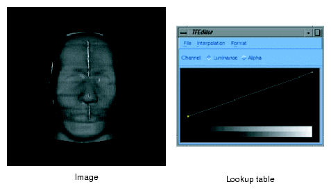
Figure 4-11 was generated using both the transfer function editor and the demo code provided with OpenGL Volumizer.
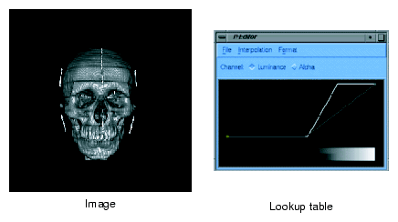
Figure 4-12 shows the skull of the head along with its lookup table.
TMRenderAction implements the transfer function using post-interpolation lookup tables. These lookup tables get applied in the imaging pipeline after the texture interpolation stage. The interface for specifying the lookup table is similar to that of the vzParameterVolumeTexture parameter since a lookup table can be thought of as a one-dimensional texture. The constructor for the class looks like the following:
vzParameterLookupTable( int width,
                      void* dataPtr,
                      vzTextureType dataType,
                      vzExternalTextureFormat externalFormat);
|
The width value specifies the number of entries in the table. The dataPtr value is the address of the table entries in memory. The dataType and externalFormat values specify the data type and format, respectively, similar to that of a vzParameterVolumeTexture parameter.
Note the following:
Unlike the vzParameterVolumeTexture parameter, the width of the lookup table must be a power of two.
The dataPtr, dataType, and dataFormat values of a lookup table can be modified once it is created. For any of these modifications, the table would be reloaded.
Like the vzParameterVolumeTexture parameter, the dataPtr value is shallow copied—that is, no memory is allocated internally for the data. Also, the data should be specified in an interleaved format similar to that of the volume texture.
The vzParameterVec3f class is used to specify a vector of three floating point values. It is used by vzTMTangentSpaceShader to specify the light direction for the volumetric lighting. It can potentially be used by other shaders that require parameters such as color values, material properties, and so on. The constructor is simply the following:
vzParameterVec3f( ); |
The vector is given a default value of (1, 0, 0). You can modify the value by using the setValue() method of the class.
TMRenderAction implements the 3D texture slicing technique (described earlier in section “Algorithm Used by TMRenderAction”) to render volumetric shapes. This section explains some of the details of the render action and mentions a few techniques that you can employ for added functionality and performance. Included are the following subsections:
Figure 4-13 shows the pipeline used by a typical volume rendering application using the render action.
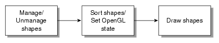
First, the application computes the number of shapes it needs to keep resident in texture memory for the given frame. The list of shapes might be the outcome of visibility culling in an immersive application, the current frame index of a time-varying simulation, or the like. Note that it is not necessary to draw all shapes that are managed, but a shape that needs to be drawn must be managed.
Next, it is the application's responsibility to sort the rendered shapes in the correct order since TMRenderAction does not perform any visibility sorting of the rendered shapes. After the sort, the application sets the appropriate OpenGL state, such as enabling blending and setting the appropriate blending functions, for performing volume rendering. TMRenderAction renders the polygonal geometry in a back-to-front sorted order. Hence, the blending function for the most common volume rendering case would be the over operator glBlendFunc(GL_SRC_ALPHA, GL_ONE_MINUS_SRC_ALPHA). The following is a typical example of the OpenGL state settings using the over operator:
glEnable(GL_BLEND); glBlendFunc(GL_SRC_ALPHA, GL_ONE_MINUS_SRC_ALPHA); |
The flexibility in choosing the blending function allows you to implement other techniques. For example, you can implement Maximum Intensity Projection by using the blending equation glBlendEquation(GL_MAX). See the man page for glBlendEquation() for a complete list of modes.
After these two steps, the application lets the render action know that it is ready to start drawing the shapes by calling beginDraw(). The beginDraw() method marks the end of the texture management phase and the beginning of the rendering phase. Inside the method, the render action does the following:
Computes total resources required for the list of managed shapes.
Manages the OpenGL state (push application's OpenGL state, store transformation matrices, etc.).
Manages the OpenGL resources (creates and downloads texture objects, lookup tables, etc.).
Then the application draws all the shapes in the visibility sorted order just described in the preceding paragraphs. Inside each draw method, the render action does the following:
Invokes the shader's initialization routine, which sets the appropriate OpenGL state (bind texture objects, enable lookup tables, etc.).
Polygonizes the volumetric geometry using the transformation matrices.
Draws the polygonized geometry in a back-to-front order.
Note that the polygonized geometry is always parallel to the viewport, unless the application has set slicing planes on the volumetric geometry. The transformation matrices are queried directly from OpenGL in the beginDraw() method. These matrices are stored and used for all the subsequent draws before the next endDraw() call.
Finally, in the endDraw() method, the render action restores the OpenGL state that it has modified. This includes texture related settings, lookup tables, and pixel store.
Texture memory is a very valuable resource that needs to be managed very efficiently if one is to achieve interactive rates for volume rendering using 3D texture mapping. TMRenderAction makes this job easier for you by hiding all the machine-specific details of texture management and giving you transparent access to the graphics hardware. The render action optimizes the texture management process by using techniques to prevent fragmentation of texture memory and optimizing the flow of texture data to the graphics subsystem.
The following subsections provide some specific details of the texture management performed by TMRenderAction:
TMRenderAction allows specifying textures of arbitrary dimensions and sizes using the vzParameterVolumeTexture class. All texture dimensions have to be powers of two for the textures to be valid. Also, the texture size should be less than or equal to the amount of texture memory available on the graphics subsystem.
TMRenderAction removes this restriction by appropriately padding the textures of invalid dimensions to the next higher power-of-two dimensions. Also, TMRenderAction is capable of virtualizing textures that are too big to fit in texture memory. Requiring no intervention in brick creation, management, and sorting, all of these processes are transparent to you.
For some applications, you might want to implement your own bricking of the texture data. In this case, you will have to create one vzShape per brick. Each of these shapes will contain one volume texture corresponding to the texture data for the brick. Once the shape is created, you should manage, unmanage, and draw these shapes as required. TMRenderAction will try to optimize the texture management, depending on the total size of the textures that you have created.
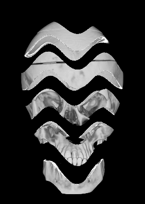
For your custom bricking, you should make sure that the geometry ROIs of the texture bricks are such that the boundaries match with those of the adjacent bricks. You should invoke the draw function in such a manner that the shapes are rendered in a back-to-front sorted order. TMRenderAction assumes linear filtering of textures; so, you should have a one-voxel overlap between the adjacent textures. Figure 4-14 illustrates this in 2D.
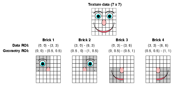
Figure 4-14 shows a 7 x 7 texture, which is divided into 4 bricks of size 4 x 4 each. These textures use the same data pointer of the original texture and do the bricking by using a different data ROI for each of the bricks. The first row gives the data ROIs of each of the bricks. In order for the brick boundaries to match, you need to adjust the geometry ROIs of each of the bricks so that they match on their boundaries. The second row gives potential values for the geometry ROIs of each brick.
TMRenderAction by default uses all of the texture memory available on the graphics subsystem. It uses GL_PROXY_TEXTURE_3D to figure out the amount of texture memory available on the system.
Understanding the texture management can help you improve the performance of the rendering by the render action in many common cases. TMRenderAction computes the total amount of resources required to render the given set of managed shapes in the beginDraw() call and compares it to the amount available on the graphics pipe. Depending on the outcome of the comparison, the render action uses different texture management schemes. One optimization common to all the schemes is that the render action tries to reuse OpenGL texture objects whenever possible. Note the sequence of frames in Figure 4-15.
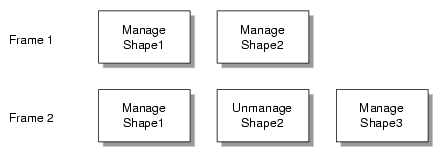
In the first frame, the render action would allocate OpenGL texture objects for Shape1and Shape2. In the second frame, even though Shape2 is not managed, the render action does not delete the texture objects for it. Instead, it reuses the texture objects for downloading and binding the textures in Shape3. This has two advantages. First, reusing texture objects prevents fragmentation of texture memory, since not all texture managers do garbage collection immediately after the texture object has been deleted. Second, for downloading the textures in Shape3, the render action uses glTexSubImage3D() calls, which are considerably faster than the corresponding glTexImage3D() calls.
The preceding discussion assumes that the textures in the shapes fit in texture memory and have the same data ROI dimensions and internal texture formats. Hence, if your application uses multiple shapes and needs to constantly manage and unmanage them in order to improve the download performance of your application, you should try to divide the whole scene into multiple shapes such that the textures in the shapes are all of equal sizes. Typical examples of such applications are volume roaming, multiresolution volume rendering, and time-varying volumes.
You can use the manage() and unmanage() methods to do predictive texture downloads of volumetric textures. For example, you could manage a shape in frame n which you need to render in frame n+1. This process can help you split the cost of downloading the textures over multiple frames. This can be very useful for applications like volume roaming, time-varying volumes, and the like.
The sampling rate used to polygonize the volumetric geometry controls the number of slices that are used to render the shape. Theoretically, the minimum data slice spacing is computed by finding the longest ray cast through the volume in the view direction, and then finding the highest frequency component of the texel values and using double that number for the minimum number of data slices for that view direction. Practically, the rendering process tends to give a pixel-fill limitation; and, in many cases, choosing the number of data slices to be equal to the volume's dimensions, measured in texels, works well. Trading performance and image quality can be a key issue for numerous applications.
You can control the sampling rate by setting the appropriate value using the setSamplingRate() method. By default, TMRenderAction uses a sampling rate of (1, 1, 1), which implies that the slicing is done once per voxel along each of the data dimensions. This default usually provides acceptable image quality.
However, when zooming into the volume data, you might see artifacts due to undersampling in the image space. In order to remove this, you might need to increase the sampling rate accordingly. Varying the sampling rate is also necessary for anisotropic data to compensate for the difference sampling rate along the various data dimensions. The sample medical data set in the following file is an example of such a data set:
VZROOT/data/medical/Phantom/CT.Head.char.tif |
Using a sampling rate of (1, 1, 3.32) would usually give better image quality for this data set.
You can render arbitrary polygonal geometry with the shape's volume texture applied to it by using the vzPolyGeometry class described in “Arbitrary Polygonal Geometry” in Chapter 3. When the draw method is invoked on the vzPolyGeometry, the appropriate geometry ROI for the polygonal data is passed with the method. The render action also sets the appropriate OpenGL state, including 3D texture state and clipping planes, before calling the draw method. So, if the shape's appearance used vzTMSimpleShader or vzTMLUTShader, the corresponding volume texture will still be bound with the appropriate lookup tables and texgen settings. Using this scheme, applications can implement the spherical sampling technique (described in the following paragraphs) by rendering the appropriate tessellated shells after the corresponding draw. There is one notable caveat, however: the technique would not work correctly with multipass shaders like vzTMTangentSpaceShader.
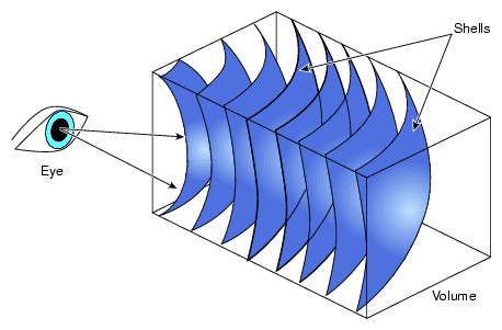
Slicing with planes is common but artifacts can appear when the observer is very close to the model. As an implementation alternative, spherical slicing provides a more accurate visualization in perspective projection. Figure 4-16 illustrates the principle.
In this case, the polygonization process might become the performance bottleneck. Using a parallel algorithm to perform the polygonization on multiple processors will help maintain a good level of performance.