Earlier chapters of this guide described libpf, IRIS Performer's high-level visual simulation development library. Much of libpf is built on top of libpr, the high-performance rendering and utility library described in this chapter.
libpr provides many useful system- and hardware-oriented utilities as well as a high-performance interface to the graphics libraries. This interface eliminates the guesswork of the tuning process by providing optimized data structures and performance-tuned renderers.
The interface is intuitive, easy to learn, and flexible enough to let you plug any application into the hooks provided by libpr to access the full set of graphics library features. libpr is platform-independent, so you can realize performance gains across the entire Silicon Graphics product line.
A great deal of specialized knowledge is required to tune the performance of any piece of software. A primary design goal of IRIS Performer is to provide you with that knowledge in the form of an easy-to-use toolkit. The design decisions implemented in libpr combine an understanding of subtle machine-level implications with hands-on experience in tuning a variety of applications.
Applications that you develop using IRIS Performer will approach peak performance on both current and future hardware and software releases, so you don't have to spend a lot of time porting and tuning your code every time you make an upgrade to your system.
libpr is a fundamental set of building blocks in much the same way that a graphics library is. It doesn't impose a multiprocessing orientation, nor is it targeted to any specific type of application; its only goal is optimizing the use of SGI graphics hardware. It can be used freely in conjunction with either the IRIS GL or the OpenGL graphics library. The library has four basic components:
high-performance immediate-mode geometry rendering
efficient management of Graphics Pipeline state
fast and flexible analytic intersection-detection support
common low-level programming utilities such as statistics gathering, window management, real-time clocks, and shared memory.
Some important features of libpr are that it
encapsulates graphics library state in objects
has a limited notion of hierarchy
doesn't extend or manage all graphics library functions
allows you to intermix graphics library and libpr calls freely
provides functionality not available in lower-level graphics libraries
is an easy porting target for applications
libpr provides highly optimized loops for rendering a wide variety of immediate-mode geometric primitives like points, lines, triangles, and triangle strips. Geometry appearance (is it textured, lit, transparent?) is determined by the current state of the Geometry Pipeline when the geometry is rendered. Efficient management of this state is crucial for best performance. To achieve the best performance, state changes must be minimized and rendering loops must be free of decisions. libpr employs two primary mechanisms for accomplishing this, pfGeoSet and pfGeoState.
Simply put, a pfGeoSet encapsulates 3D geometry while a pfGeoState encapsulates the appearance parameters known as pipeline state. A pfGeoSet is drawn—its vertices and other attributes are sent to the graphics library to be processed and ultimately rasterized on the screen. A pfGeoState is applied—its encapsulated state is used to configure the graphics library for a particular appearance, such as lit, textured, and fogged. A pfGeoSet can, and usually does, reference a pfGeoState thereby defining a both geometry and specific appearance attributes. When the pfGeoSet is then drawn, its associated pfGeoState is automatically applied first so that the geometry is rendered with the proper appearance.
Some specific libpr features and primitives discussed in this chapter are listed below:
Fast rendering of geometry with a pfGeoSet,
3D Fonts with pfFont and pfString,
Efficient state management with pfGeoStates and pfStates,
Rendering effects with pfDecal for coplanar geometry, pfFog, pfLPointState, and pfHighlight,
Texturing with pfTexture, pfTexEnv, and pfTexGen,
Lighting with pfLight, pfLightModel, and pfMaterial,
3D transformations with pfSprites and pfMatrix,
Flexible and efficient immediate mode display lists with pfDispList,
Windowing with pfWindows,.
Real-time clocks, and,
Memory management with pfMemory, pfList, pfObject, pfDataPool, pfCycleMemory and pfCycleBuffer.
All libpr geometry is defined by modular units that employ a flexible specification method. These basic groups of geometric primitives are termed pfGeoSets.
A pfGeoSet is a collection of geometry that shares certain characteristics. All items in a pfGeoSet must be of the same primitive type (whether they're points, lines, or triangles) and share the same set of attribute bindings (you can't specify colors-per-vertex for some items and colors-per-primitive for others in the same pfGeoSet). A pfGeoSet forms primitives out of lists of attributes that may be either indexed or nonindexed. An indexed pfGeoSet uses a list of unsigned short integers to index an attribute list. (See “Attributes” for information about attributes and bindings.)
Indexing provides a more general mechanism for specifying geometry than hard-wired attribute lists and also has the potential for substantial memory savings as a result of shared attributes. Nonindexed pfGeoSets are sometimes easier to construct, usually a bit faster to render, and may save memory (since no extra space is needed for index lists) in situations where vertex sharing isn't possible. A pfGeoSet must be either completely indexed or completely nonindexed; it's not legal to have some attributes indexed and others nonindexed.
 | Note: libpf applications can include pfGeoSets in the scene graph with the pfGeode (Geometry Node). |
Table 10-1 lists a subset of the routines that manipulate pfGeoSets.
Function | Description |
|---|---|
pfNewGSet | |
pfDelete | |
pfCopy | |
pfGSetGState | |
pfGSetGStateIndex | |
pfGSetNumPrims | |
pfGSetPrimType | |
pfGSetPrimLengths | |
pfGSetAttr | |
pfGSetDrawMode | |
pfGSetLineWidth | |
pfGSetPntSize | |
pfGSetHlight | |
pfDrawGSet | |
pfGSetBBox | |
pfGSetIsectMask | |
pfGSetIsectSegs | |
pfQueryGSet | |
pfPrint |
All primitives within a given pfGeoSet must be of the same type. To set the type of all primitives in a pfGeoSet named gset, call pfGSetPrimType(gset, type). Table 10-2 lists the primitive type tokens, the primitive types that they represent, and the number of vertices in a coordinate list for that type of primitive.
Table 10-2. Geometry Primitives
Token | Primitive Type | Number of Vertices |
|---|---|---|
Points | numPrims | |
Independent line segments | 2 * numPrims | |
Strips of connected lines | Sum of lengths array | |
Strips of flat-shaded lines | Sum of lengths array | |
Independent triangles | 3 * numPrims | |
Strips of connected triangles | Sum of lengths array | |
Strips of flat-shaded triangles | Sum of lengths array | |
Independent quadrilaterals | 4 * numPrims | |
Independent polygons | Sum of lengths array |
where the parameters in the last column represent:
Connected primitive types (line strips, triangle strips, and polygons) require a separate array that specifies the number of vertices in each primitive. Length is defined as the number of vertices in a strip for STRIP primitives and is the number of vertices in a polygon for the POLYS primitive type. The number of line segments in a line strip is numVerts - 1, while the number of triangles in a triangle strip and polygon is numVerts - 2. Use pfGSetPrimLengths() to set the length array for strip primitives.
The number of primitives in a pfGeoSet is specified by pfGSetNumPrims(gset, num). For strip and polygon primitives, num is the number of strips or polygons in gset.
In addition to the primitive type, pfGSetDrawMode() further defines how a primitive is drawn. Triangles, triangle strips, quadrilaterals and polygons can be specified as either filled or as wireframe, where only the outline of the primitive is drawn. Use the PFGS_WIREFRAME argument to enable/disable wireframe mode. Another argument, PFGS_FLATSHADE, specifies how the primitive should be shaded. If flat shading is enabled, each primitive or element in a strip is shaded with a single color.
pfGeoSets are normally processed in immediate mode which means that pfDrawGSet() sends attributes from the user-supplied attribute arrays to the Graphics Pipeline for rendering. However, this kind of processing is subject to some overhead, particularly if the pfGeoSet contains few primitives. In some cases it may help to use GL display lists (this is different from the libpr display list type pfDispList) or compiled mode. In compiled mode, pfGeoSet attributes are copied from the attribute lists into a special data structure called a display list during a compilation stage. This data structure is highly optimized for efficient transfer to the graphics hardware. However, compiled mode has some major disadvantages:
compilation is usually costly
a display list must be recompiled whenever its pfGeoSet's attributes change
the display list uses extra memory
In general, immediate-mode will offer excellent performance with minimal memory usage and no restrictions on attribute volatility which is a key aspect in may advanced applications.. Despite this, experimentation may show cases where compiled mode offers a performance benefit.
To enable or disable compiled mode, call pfGSetDrawMode() with the PFGS_COMPILE_GL token. When enabled, compilation is delayed until the next time the pfGeoSet is drawn with pfDrawGSet(). Subsequent calls to pfDrawGSet() will then send the compiled pfGeoSet to the graphics hardware.
A pfGeoSet requires a coordinate array that specifies the world coordinate positions of primitive vertices. This array is either indexed or not, depending on whether a coordinate index list is supplied. If the index list is supplied, it's used to index the coordinate array; if not, the coordinate array is interpreted in a sequential order.
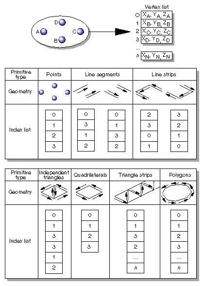
A pfGeoSet's primitive type dictates the connectivity from vertex to vertex to define geometry. Figure 10-1 shows a coordinate array consisting of four coordinates, A, B, C, and D, and the geometry resulting from different primitive types. This example uses index lists that index the coordinate array. Note that the flat-shaded line strip and flat-shaded triangle strip primitives have the vertices listed in the same order as for the smooth-shaded varieties.
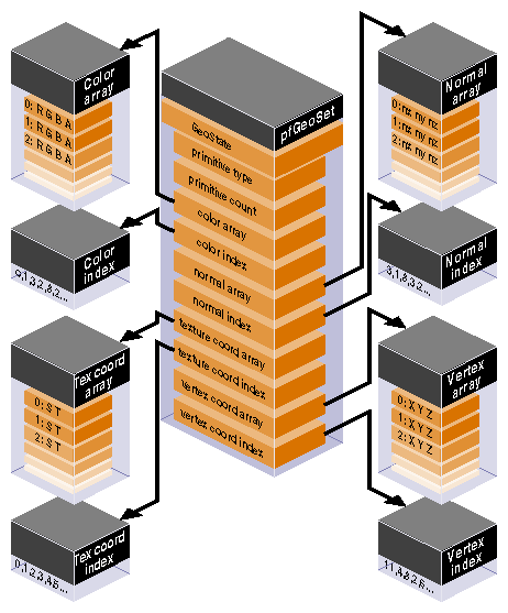
The definition of a primitive isn't complete without attributes. In addition to a primitive type and count, a pfGeoSet references four attribute arrays (see Figure 10-2):
colors (red, green, blue, alpha)
normals (Nx, Ny, Nz)
texture coordinates (S, T)
vertex coordinates (X, Y, Z)
(A pfGeoState is also associated with each pfGeoSet; see “Graphics State” and Figure 10-3 for details.) The four components listed above can be specified with pfGSetAttr() and in two ways: by indexed specification—using a pointer to an array of components and a pointer to an array of indices; or by direct specification—providing a NULL pointer for the indices, which indicates that the indices are sequential from the initial value of zero. The choice of indexed or direct components applies to an entire pfGeoSet; that is, all of the supplied components within one pfGeoSet must use the same method. However, you can emulate partially indexed pfGeoSets by using indexed specification and making each nonindexed attribute's index list be a single shared “identity mapping” index array whose elements are 0, 1, 2, 3,…, N-1 where N is the largest number of attributes in any referencing pfGeoSet. (You can share the same array for all such emulated pfGeoSets.). The direct method avoids one level of indirection and may have a performance advantage compared with indexed specification for some combinations of CPU and graphics subsystem.
Attribute bindings specify where in the definition of a primitive an attribute has effect. You can leave a given attribute unspecified; otherwise, its binding location is one of the following:
overall (one value for the entire pfGeoSet)
per primitive
per vertex
Only certain binding types are supported for some attribute types.
Table 10-3 shows the attribute bindings that are legal for each type of attribute.
Table 10-3. Attribute Bindings
Binding Token | Color | Normal | Texture Coordinate | Coordinate |
|---|---|---|---|---|
Yes | Yes | No | No | |
Yes | Yes | No | No | |
Yes | Yes | Yes | Yes | |
Yes | Yes | Yes | No |
Attribute lists, index lists, and binding types are all set by pfGSetAttr().
For FLAT primitives (PFGS_FLAT_TRISTRIPS, PFGS_FLAT_LINESTRIPS), the PFGS_PER_VERTEX binding for normals and colors has slightly different meaning. In these cases, per-vertex colors and normals should not be specified for the first vertex in each line strip or for the first two vertices in each triangle strip since FLAT primitives use the last vertex of each line segment or triangle to compute shading.
There are many operations you can perform on pfGeoSets. pfDrawGSet() “draws “the indicated pfGeoSet by sending commands and data to the Geometry Pipeline, unless IRIS Performer's display-list mode is in effect. In display-list mode, rather than sending the data to the pipeline, the current pfDispList “captures” the pfDrawGSet() command. The given pfGeoSet is then drawn along with the rest of the pfDispList with the pfDrawDList() command.
When the PFGS_COMPILE_GL mode of a pfGeoSet is not active (pfGSetDrawMode()), pfDrawGSet() uses rendering loops tuned for each primitive type and attribute binding combination to reduce CPU overhead in transferring the geometry data to the hardware pipeline. Otherwise, pfDrawGSet() sends a special, compiled data structure.
Table 10-1 lists other operations that you can perform on pfGeoSets. pfCopy() does a shallow copy, copying the source pfGeoSet's attribute arrays by reference and incrementing their reference counts. pfDelete() frees the memory of a pfGeoSet and its attribute arrays (if those arrays were allocated with pfMalloc() and provided their reference counts reach zero). pfPrint() is strictly a debugging utility and will print a pfGeoSet's contents to a specified destination. pfGSetIsectSegs() allows intersection testing of line segments against the geometry in a pfGeoSet; see “Intersecting With pfGeoSets” in Chapter 11 for more information on that function.
In addition to the pfGeoSet, libpr offers two other primitives which together are useful for rendering a specific type of geometry—three-dimensional characters. See Chapter 5, “Nodes and Node Types” and the description for pfText nodes for an example of how to set up three-dimension text within the context of libpf.
The basic primitive supporting text rendering is the libpr pfFont primitive. A pfFont is essentially a collection of pfGeoSets in which each pfGeoSet represents one character of a particular font. pfFonts also contain metric data, such as a per-character spacing, the three-dimensional escapement offset used to increment a text `cursor' after the character has been drawn. Thus, pfFonts maintain all of the information that is necessary to draw any and all valid characters of a font. However, note that pfFonts are passive and have little functionality on their own, for example you cannot draw a pfFont—it simply provides the character set for the next higher-level text data object, the pfString.
Table 10-4 lists some routines that are used with a pfFont.
Example 10-1. Loading Characters into a pfFont
/* Setting up a pfFont */
pfFont *ReadFont(void)
{
pfFont *fnt = pfNewFont(pfGetSharedArena());
for(i=0;i<numCharacters;i++)
{
pfGeoSet* gset = getCharGSet(i);
pfVec3* spacing = getCharSpacing(i);

pfFontCharGSet(fnt, i, gset);
pfFontCharSpacing(fnt, i, spacing);
}
}
|
Simple rendering of three-dimensional text can be done using a pfString. A pfString is an array of font indices stored as 8-bit bytes, 16-bit shorts, or 32-bit integers. Each element of the array contains an index to a particular character of a pfFont structure. A pfString can not be drawn until it has been associated with a pfFont object via a call to pfStringFont(). To render a pfString once it references a pfFont, call the function pfDrawString().
pfStrings support the notion of `flattening' to trade off memory for faster processing time. This will cause individual, non-instanced geometry to be used for each character, eliminating the cost of translating the text cursor between each character when drawing the pfString.
Example 10-2. Setting up and drawing a pfString
/* Create a string a rotate it for 2.5 seconds */
void
LoadAndDrawString(const char *text)
{
pfFont *myfont = ReadMyFont();
pfString *str = pfNewString(NULL);
pfMatrix mat;
float start,t;

/* Use myfont as the 3-d font for this string */
pfStringFont(str, fnt);

/* Center String */
pfStringMode(str, PFSTR_JUSTIFY, PFSTR_MIDDLE);

/* Color String is Red */
pfStringColor(str, 1.0f, 0.0f, 0.0f, 1.0f);

/* Set the text of the string */
pfStringString(str, text);

/* Obtain a transform matrix to place this string */
GetTheMatrixToPlaceTheString(mat);
pfStringMat(str, &mat);

/* optimize for draw time by flattening the transforms */
pfFlattenString(str);

/* Twirl text for 2.5 seconds */
start = pfGetTime();
do
{
pfVec4 clr;
pfSetVec4(clr, 0.0f, 0.0f, 0.0f, 1.0f);

/* Clear the screen to black */
pfClear(PFCL_COLOR|PFCL_DEPTH, clr);

t = (pfGetTime() - start)/2.5f;
t = PF_MIN2(t, 1.0f);

pfMakeRotMat(mat, t * 315.0f, 1.0f, 0.0f, 0.0f);
pfPostRotMat(mat, mat, t * 720.0f, 0.0f, 1.0f, 0.0f);

t *= t;
pfPostTransMat(mat, mat, 0.0f,
150.0f * t + (1.0f - t) * 800.0f, 0.0f);

pfPushMatrix();
pfMultMatrix(mat);

/* DRAW THE INPUT STRING */
pfDrawString(str);

pfPopMatrix();

pfSwapWinBuffers(pfGetCurWin());
} while(t < 2.5f);
}
|
Table 10-5 lists the key routines used to manage pfStrings.
The graphics libraries are immediate-mode state machines; if you set a mode, all subsequent geometry is drawn in that mode. For the best performance, mode changes need to be minimized and managed carefully. libpr manages a subset of graphics library state and identifies bits of state as graphics state elements. Each state element is identified with a PFSTATE token, e.g., PFSTATE_TRANSPARENCY corresponds to the transparency state element. State elements are loosely partitioned into three categories: modes, values and attributes.
Modes are the graphics state variables, such as transparency and texture enable, that have simple values like ON and OFF. An example of a mode command is pfTransparency(mode).
Values are not modal, rather they are real numbers which signify a threshold or quantity. An example of a value is the reference alpha value specified with the pfAlphaFunc() command.
Attributes are references to encapsulations (structures) of graphics state. They logically group the more complicated elements of state, such as textures and lighting models. Attributes are structures that are modified through a procedural interface and must be applied to have an effect. For example, pfApplyTex(tex) applies the texture map, tex, to subsequently drawn geometry.
In libpr, there are three methods of setting state:
immediate mode
display list mode
pfGeoState mode
Like the graphics libraries, libpr supports the notion of both immediate and display-list modes. In immediate mode, graphics mode changes are sent directly to the Geometry Pipeline, i.e., they have immediate effect. In display-list mode, graphics mode changes are captured by the currently active pfDispList, which can be drawn later. libpr display lists differ from graphics library objects because they capture only libpr commands and are reusable. libpr display lists are useful for multiprocessing applications in which one process builds up the list of visible geometry and another process draws it. “Display Lists” describes libpr display lists.
A pfGeoState is a structure that encapsulates all the graphics modes and attributes that libpr manages. You can individually set the state elements of a pfGeoState to define a graphics context. The act of applying a pfGeoState with pfApplyGState() configures the state of the Geometry Pipeline according to the modes, values, and attributes set in the pfGeoState. For example, the following code fragment shows equivalent ways (except for some inheritance properties of pfGeoStates described later) of setting up some lighting parameters suitable for a glass surface:
/* Immediate mode state specification */ pfMaterial *shinyMtl; pfTransparency(PFTR_ON); pfApplyMtl(shinyMtl); pfEnable(PFEN_LIGHTING); /* is equivalent to: */ /* GeoState state specification */ pfGeoState *gstate; pfGStateMode(gstate, PFSTATE_TRANSPARENCY, PFTR_ON); pfGStateAttr(gstate, PFSTATE_FRONTMTL, shinyMtl); pfGStateMode(gstate, PFSTATE_ENLIGHTING, PF_ON); pfApplyGState(gstate); |
In addition, pfGeoStates have unique state inheritance capabilities that make them very convenient and efficient; they provide independence from ordered drawing. pfGeoStates are described in the “pfGeoState” section of this chapter.
Libpr routines have been designed to produce an efficient structure for managing graphics state. You can also set graphics state directly through the GL. However, libpr will have no record of these settings and will not be able to optimize them and may make incorrect assumptions about current graphics state if the resulting state does not match the libpr record when libpr routines are called. Therefore, it is best to use the libpr routines whenever possible to change graphics state and to restore libpr state if you go directly through the GL.
The following sections will describe the rendering geometry and state elements in detail. There are three types of state elements: modes, values and attributes. Modes are simple settings that take a set of integer values that include values for enabling and disabling the mode. Modes may also have associated values that allow a setting from a defined range. Attributes are complex state structures that encapsulate a related collection of modes and values. Attribute structures will not include in their definition an enable or disable as the enabling or disabling of a mode is orthogonal to the particular related attribute in use.
libpr manages a subset of the rendering modes found in the graphics libraries. In addition, libpr abstracts certain concepts like transparency, providing a higher-level interface that hides the underlying implementation mechanism.
libpr provides tokens that identify the modes that it manages. These tokens are used by pfGeoStates and other state-related functions like pfOverride(). The following table enumerates the PFSTATE_ tokens of supported modes, each with a brief description and default value.
Table 10-6 lists and describes the mode tokens.
Table 10-6. pfGeoState Mode Tokens
Token Name | Description | Default Value |
|---|---|---|
Transparency modes | ||
Alpha function | ||
Antialiasing mode | ||
Face culling mode | ||
Decaling mode for coplanar geometry | ||
Shading model |
GOURAUD | |
Lighting enable flag | ||
Texturing enable flag | ||
Fogging enable flag | ||
pfGeoSet wireframe mode enable flag | PF_OFF | |
pfGeoSet colortable enable flag | PF_OFF | |
pfGeoSet highlighting enable flag | PF_OFF | |
pfGeoSet light point state enable flag | PF_OFF | |
Texture coordinate generation enable flag | PF_OFF |
The mode control functions described in the following sections should be used in place of their graphics library counterparts so that IRIS Performer can correctly track the graphics state. Use pfGStateMode() with the appropriate PFSTATE token to set the mode of a pfGeoState.
You can control transparency using pfTransparency(). Possible transparency modes are:
Table 10-7. pfTransparency Tokens
Transparency mode | Description |
|---|---|
Transparency disabled. | |
Use the fastest, but not necessarily the best, transparency provided by the hardware. | |
Use the best, but not necessarily the fastest, transparency provided by the hardware. | |
Use screen-door transparency when multisampling. Fast but limited number of transparency levels. | |
Use alpha-based blend with background color. Slower but high number of transparency levels. |
In addition, the flag PFTR_NO_OCCLUDE may be logically OR-ed into the transparency mode in which case geometry will not write depth values into the frame buffer. This will prevent it from occluding subsequently rendered geometry. Enabling this flag improves the appearance of unordered, blended transparent surfaces.
There are two basic transparency mechanisms: screen-door transparency which requires hardware multisampling and blending. Blending offers very high quality transparency but for proper results requires that transparent surfaces be rendered in back-to-front order after all opaque geometry has been drawn. When using transparent texture maps to “etch” geometry or if the surface has constant transparency, screen-door transparency is usually good enough. Blended transparency is usually required to avoid “banding” on surfaces with low transparency gradients like clouds and smoke.
Selects flat shading or Gouraud (smooth) shading. pfShadeModel() takes one of two tokens: PFSM_FLAT or PFSM_GOURAUD. One some graphics hardware flat shading can offer a significant performance advantage.
pfAlphaFunc() is an extension of the IRIS GL function afunction(3g) and the OpenGL function glAlphaFunc(); it allows IRIS Performer to keep track of the hardware mode. The alpha function is a pixel test that compares the incoming alpha to a reference value and uses the result to determine whether or not the pixel is rendered. The reference value must be specified in the range [0, 1]. For example, a pixel whose alpha value is 0 is not rendered if the alpha function is PFAF_GREATER and the alpha reference value is also 0. Note that rejecting pixels based alpha can be faster than using transparency alone. A common technique for improving the performance of filling polygons is to set an alpha function that will reject pixels of low (possibly non-zero) contribution. Alpha function is typically used for see-through textures like trees.
On Z-buffer based graphics hardware, coplanar geometry can cause unwanted artifacts due to the finite numerical precision of the hardware which cannot accurately resolve which surface has visual priority. This can result in flimmering, a visual “tearing” or “twinkling” of the surfaces. pfDecal() is used to accurately draw coplanar geometry on IRIS platforms and it supports two implementation methods, each with its advantages:
The stencil decaling method uses a hardware resource known as a stencil buffer and requires that a single stencil plane (see IRIS GL stencil() and OpenGL glStencilOp() man pages) be available for IRIS Performer. This method offers the highest image quality but requires that geometry be coplanar and rendered in a specific order which reduces opportunities for the performance advantage of sorting by graphics mode.
A potentially faster method is the displace decaling method. In this case, each layer is displaced towards the eye so it “hovers” slightly above the preceding layer. Displaced decals need not be coplanar, can be drawn in any order but the displacement may cause geometry to incorrectly “poke through” other geometry.
Decals consist of base geometry and layer geometry. The base defines the depth values of the decal while layer geometry is simply “inlaid” on top of the base. Multiple layers are supported but limited to 8 when using displaced decals. Realize that these layers imply superposition; there is no limit to the number of polygons in a layer, only to the number of distinct layers.
The decal mode indicates whether the subsequent geometry is base or layer and the decal method to use. For example, a mode of PFDECAL_BASE_STENCIL means that subsequent geometry is to be considered as base geometry and drawn using the stencil method. All combinations of base/layer and displace/stencil modes are supported but you should make sure to use the same method for a given base-layer pair.
Example 10-3 illustrates the use of pfDecal().
Example 10-3. Using pfDecal() to draw road with stripes
pfDecal(PFDECAL_BASE_STENCIL); /* ... draw underlying geometry (roadway) here ...*/ pfDecal(PFDECAL_LAYER_STENCIL); /* ... draw coplanar layer geometry (stripes) here ... */ pfDecal(PFDECAL_OFF); |
| Note: libpf applications can use the pfLayer node to include decals within a scene graph. |
pfCullFace() controls which side of a polygon (if any) is discarded in the Geometry Pipeline. Polygons are either front-facing or back-facing. A front-facing polygon is described by a counterclockwise order of vertices in screen coordinates, and a back-facing one has a clockwise order. pfCullFace() has four possible arguments:
| PFCF_OFF | Disable face-orientation culling | |
| PFCF_BACK | Cull back-facing polygons | |
| PFCF_FRONT | Cull front-facing polygons | |
| PFCF_BOTH | Cull both front- and back-facing polygons |
In particular, backface culling is highly recommended since it offers a significant performance advantage for databases where polygons are never be seen from both sides (databases of “solid” objects or with constrained eyepoints).
pfAntialias() is used to turn the antialiasing mode of the hardware on or off. Currently, antialiasing is implemented differently by each different graphics system. Antialiasing can produce artifacts as a result of the way IRIS Performer and the active hardware platform implement the feature. See the reference page for pfAntialias() for implementation details.
Some modes may also have associated values. These values are set through pfGStateVal(). Table 10-8 lists and describes the value tokens.
Table 10-8. pfGeoState Value Tokens
Token Name | Description | Range | Default Value |
|---|---|---|---|
Set the alpha function reference value. | 0.0 - 1.0 | 0.0 |
pfEnable() and pfDisable() control certain rendering modes. Certain modes do not have effect when enabled but require that other attribute(s) be applied. Table 10-9 lists and describes the tokens and also lists the attributes required for the mode to become truly active.
Table 10-9. Enable and Disable Tokens
Token | Action | Attribute(s) Required |
|---|---|---|
Enable or disable lighting. | pfMaterial | |
Enable or disable texture. | pfTexEnv | |
Enable or disable fog. | pfFog | |
Enable or disable pfGeoSet wireframe rendering. | none | |
Enable or disable pfGeoSet colortable mode. | pfColortable | |
Enable or disable pfGeoSet highlighting. | pfHighlight | |
Enable or disable automatic texture coordinate generation. | pfTexGen | |
Enable or disable pfGeoSet light points | pfLPointState |
By default all modes are disabled.
Rendering attributes are state structures that are manipulated through a procedural interface. Examples include pfTexture, pfMaterial, and pfFog. libpr provides tokens that enumerate the graphics attributes it manages. These tokens are used by pfGeoStates and other state-related functions like pfOverride(). Table 10-10 lists and describes the tokens.
Table 10-10. Rendering Attribute Tokens
Attribute Token | Description | Apply Routine |
|---|---|---|
Lighting model | ||
Light source definitions | ||
Front-face material | ||
Back-face material | ||
Texture | ||
Texture environment | ||
Fog model | ||
Color table for pfGeoSets | ||
Definition of pfGeoSet highlighting style | ||
pfGeoSet light point definition | ||
Texture coordinate generation definition |
Rendering attributes control which attributes are applied to geometric primitives when they're processed by the hardware. All IRIS Performer attributes consist of a control structure, definition routines, and an apply function, pfApply* (except for lights which are “turned on”).
Each attribute has an associated pfNew*() routine that allocates storage for the control structure. When sharing attributes across processors in a multiprocessor application, you should pass the pfNew*() routine a shared memory arena from which to allocate the structure. If you pass NULL as the arena, the attribute is allocated from the heap and isn't sharable in a non-shared address space (fork()) multiprocessing application.
All attributes can be applied directly, referenced by a pfGeoState or captured by a display list. When changing an attribute, that change isn't visible until the attribute is reapplied. Detailed coverage of attribute implementation is available in the reference pages.
IRIS Performer supports texturing through pfTextures and pfTexEnvs, which are roughly analogous to graphics library textures (see texdef2d() for IRIS GL, or glTexImage2D() for OpenGL) and texture environments (see IRIS GL's tevdef(3g) or OpenGL's glTexEnv()). A pfTexture defines a texture image, format, and filtering. A pfTexEnv specifies how the texture should interact with the colors of the geometry it's applied to. You need both to display textured data, but you don't need to specify them both at the same time. For example, you could have pfGeoStates each of which had a different texture specified as an attribute and still use an overall texture environment specified with pfApplyTEnv().
A pfTexture is created by calling pfNewTex(). If the desired texture image exists as a disk file in IRIS libimage format (the file often has a “.rgb” suffix), you can call pfLoadTexFile() to load the image into CPU memory and set the image format. Otherwise, pfTexImage() lets you directly provide an image array in the same external format as specified on the pfTexture and as expected by texdef2d() in IRIS GL and glTexImage2D() in OpenGL. IRIS GL and OpenGL both expect packed texture data with each row beginning on a long word boundary. However, IRIS GL and OpenGL expect the individual components of a texel to be packed in opposite order. For example, IRIS GL expects four component texels to be packed as ABGR OpenGL expects the texels to be packed as RGBA. If you provide your own image array in a multiprocessing environment, it should be allocated from shared memory (along with your pfTexture) to allow different processes to access it.
| Note: The size of your texture must be an integral power of two on each side. IRIS GL scales up your textures to the next power of two, making them take up to four times more space in hardware texture memory! OpenGL simply refuses to accept badly sized textures. You can rescale your texture images with the izoom or imgworks programs (shipped with IRIX 5.3 in the eoe2.sw.imagetools and imgtools.sw.tools subsystems; and with IRIX 6.2 in the eoe.sw.imagetools and imgworks.sw.tools subsystems). |
Your texture source does not have to be a static image. pfTexLoadMode() can be used to set one of the sources listed in Table 10-11 with PFTEX_LOAD_BASE. Note that sources other than CPU memory may not be supported on all graphics platforms, or may have some special restrictions. The sample program, /usr/share/Performer/src/pguide/libpr/C/movietex.c demonstrates the use of different texture sources for playing texture or video movies on pfGeoSet “screens”. Changing your image source may cause your texture to go through the formatting stage upon the next pfApplyTex().
Table 10-11. Texture Image Sources
Texture storage is limited only by virtual memory, but for real-time applications you must consider the amount of texture storage the graphics hardware supports. Textures that don't fit in the graphics subsystem will be paged as needed when pfApplyTex() is called. Libpr provides routines for managing hardware texture memory so that a real-time application does not have to get a surprise texture load. pfIsTexLoaded(), called from the drawing process, will tell you if the pfTexture is currently properly loaded in texture memory. pfIdleTex() can be used to free up the hardware texture memory owned by a pfTexture.
pfLoadTex(), called from the drawing process, can be used to explicitly load a texture into graphics hardware texture memory (which will include doing any necessary formatting of the texture image). By default, pfLoadTex() will load the entire texture image, including any required minification or magnification levels, into texture memory. pfSubloadTex() and pfSubloadTexLevel() can also be used in the drawing process to do an immediate load of texture memory managed by the given pfTexture and these routines allow you to specify all loading parameters (source, origin, size, etc.). This is useful for loading different images for the same pfTexture in different graphics pipelines.
A special pfTexFormat() formatting mode, PFTEX_SUBLOAD_FORMAT, allows part or all of the image in texture memory owned by the pfTexture to be replaced via pfApplyTex(), pfLoadTex(), or pfSubloadTex(), without having to go through the expensive reformatting phase. This allows you to quickly update the image of a pfTexture in texture memory. The PFTEX_SUBLOAD_FORMAT used with an appropriate pfTexLoadSize() and pfTexLoadOrigin() allows you to control what part of the texture will be loaded by subsequent calls to pfLoadTex() or pfApplyTex(). There are also different loading modes that cause pfApplyTex() to automatically reload or subload a texture from a specified source. If you want the image of a pfTexture to be updated upon every call to pfApplyTex(), you can set the loading mode of the pfTexture with pfTexLoadMode() to be PFTEX_BASE_AUTO_REPLACE. pfTexLoadImage() allows you to continuously update the memory location of an IMAGE source texture without triggering any reformatting of the texture.
There may also be formatting modes for internal or external image formats that IRIS Performer does not have a token for. However, the GL value can be specified. Specifying GL values will make your application GL specific and may also cause future porting problems, so it should only be done if absolutely necessary.
pfTextures also allow you to define a set of textures that are mutually exclusive, should always be applied to the same set of geometry, and thus that can share the same location in hardware texture memory. With pfTexList(tex, list) you can specify a list of textures to be in a texture set managed by the base texture, tex. The base texture is what gets applied with pfApplyTex(), or assigned to geometry through pfGeoStates. With pfTexFrame(), you can select a given texture from the list (-1 selects the base texture and is the default). This allows you to define a texture movie where each image is the frame of the movie. You can have an image on the base texture to display when the movie is not playing. There are additional loading modes for pfTexLoadMode() described in Table 10-12 to control how the textures in the texture list share memory with the base texture.
Table 10-12. Texture Load Modes
PFTEX_LOAD_ modeToken | Load mode values | Description: |
|---|---|---|
Loading of image is done as required for pfApply, or automatically subloaded upon every pfApply. | ||
Loading of list texture image is as separate apply, causes freeing of previous list texture in hardware texture memory, or is subloaded into memory managed by the base texture. |
pfTexFilter() sets a desired filter on a pfTexture. The minification and magnification texture filters are described with bitmask tokens. If filters are partially specified, IRIS Performer will fill in the rest with machine dependent fast defaults. The PFTEX_FAST token can be included in the bitmask to allow IRIS Performer to make machine dependent substitutions where there are large performance differences.
There are a variety of texture filter functions that can improve the look of textures when they are minified and magnified. By default, textures use MIPmapping when minified (though this costs an extra 1/3 in storage space to store the minification levels). Each level of minification or magnification of a texture is twice the size of the previous level. Minification levels are indicated with positive numbers and magnification levels are indicated with non-positive numbers. The default magnification filter for textures is bilinear interpolation. The use of detail textures and sharpening filters can improve the look of magnified textures. Detailing actually uses an extra detail texture that you provide that is based on a specified level of magnification from the corresponding base texture. The detail texture can be specified with the pfTexDetail() command. By default, MIPmap levels are generated for the texture automatically. OpenGL operation allows for the specification of custom MIPmap levels. Both MIPmap levels and detail levels can be specified with pfTexLevel(). The level number should be a positive number for a minification level and a non-positive number for a magnification (detail) level. If you are providing your own minification levels, you must provide all log2(MAX(texSizeX, texSizeY)) minification levels. There is only one detail texture for a pfTexture.
The magnification filters use spline functions to control their rate of application as a function of magnification, and specified level of magnification for detail textures. These splines can be specified with pfTexSpline(). The specification of the spline is a set of control points that are pairs of non-decreasing magnification levels (specified with non-positive numbers) and corresponding scaling factors. Magnification filters can be applied to all components of a texture, only the RGB components of a texture, or to just the alpha components. OpenGL does not allow different magnification filters (between detail and sharpen) for RGB and alpha channels.
| Note: The specification of detail textures may have GL dependencies and magnifications filters may not be available on all hardware configurations. The pfTexture reference page describes these details. |
Automatic texture coordinate generation is provided with the pfTexGen state attribute. pfTexGen closely corresponds to IRIS GL's texgen() and OpenGL's glTexGen() functions. When texture coordinate generation is enabled, a pfTexGen applied with pfApplyTGen() will automatically generate texture coordinates for all rendered geometry. Texture coordinates are generated from geometry vertices according to the texture generation mode set with pfTGenMode(). Available modes and their function are listed in Table 10-13. Some modes refer to a plane which is set with pfTGenPlane().
Table 10-13. Texture generation modes
PFTG_ Mode Token | Texture coordinates are calculated as... |
|---|---|
distance of vertex from plane in object coordinates | |
distance of vertex from plane in eye coordinates. The plane is transformed by the inverse of the ModelView matrix when the pfTexGen is applied. | |
distance of vertex from plane in eye coordinates. The plane is not transformed by the inverse of the ModelView matrix when the pfTexGen is applied | |
an index into a 2D reflection map based on vertex position and normal. Specifics of the calculation are found in the graphics libraries' man pages. |
IRIS Performer lighting is an extension of graphics library lighting (see lmdef(3g) for IRIS GL or glLight() and related functions in OpenGL), but IRIS Performer divides the actions of lmdef() into lights and light models, just as OpenGL does. The light embodies the color, position, and type (for example, infinite or spot) of the light. The light model specifies the environment for infinite (the default) or local viewing, and two-sided illumination. pfLights and pfLightModels are created by calling pfNewLight() and pfNewLModel(), respectively.
The transformation matrix that is on the matrix stack at the time the light is applied controls the interpretation of the light source direction:
To attach a light to the viewer (like a miner's head-mounted light), call pfLightOn() only once with an identity matrix on the stack.
To attach a light to the world (like the sun or moon), call pfLightOn() every frame with only the viewing transformation on the stack.
To attach a light to an object (like the headlights of a car), call pfLightOn() every frame with the combined viewing and modeling transformation on the stack.
The number of lights you can have turned on at any one time is limited by PF_MAX_LIGHTS, just as is true with the graphics libraries.
| Note: libpf applications can include light sources in a scene graph with the pfLightSource node. |
IRIS Performer materials are an extension of graphics library materials (see lmdef(3g) for IRIS GL or glMaterial() for OpenGL). pfMaterials encapsulate the ambient, diffuse, specular, and emissive colors of an object as well as its shininess and transparency. A pfMaterial is created by calling pfNewMtl(). As with any of the other attributes, a pfMaterial can be referenced in a pfGeoState, captured by a display list, or invoked as an immediate mode command.
pfMaterials, by default, allow object colors to set the ambient and diffuse colors. This allows the same pfMaterial to be used for objects of different colors, removing the need for material changes and thus improving performance. This mode can be changed with pfMtlColorMode(mtl, side, PFMTL_CMODE_*). IRIS GL only supports the front material tracking the current color while OpenGL allows front or back materials to track the current color. If the same material is used for both front and back materials, there is no difference in functionality.
A pfColortable substitutes its own color array for the normal color attribute array (PFGS_COLOR4) of a pfGeoSet. This allows the same geometry to appear differently in different views simply by applying a different pfColortable for each view. By leaving the selection of color tables to the global state, you can use a single call to switch color tables for an entire scene. In this way, color tables can simulate time-of-day changes, infrared imaging, psychedelia, and other effects.
pfNewCtab() creates and returns a handle to a pfColortable. As with other attributes, you can specify which color table to use in a pfGeoState or you can use pfApplyCtab() to set the global color table, either in immediate mode or in a display list. For an applied colortable to have effect, colortable mode must also be enabled.
A pfFog is created by calling pfNewFog(). As with any of the other attributes, a pfFog can be referenced in a pfGeoState, captured by a display list, or invoked as an immediate mode command. Fog is the atmospheric effect of aerosol water particles that occlude vision over distance. The IRIS hardware can simulate this phenomenon in several different fashions. A fog color is blended with the resultant pixel color based on the range from the viewpoint and the fog function. pfFog supports several different fogging methods. Table 10-14 lists the pfFog tokens and their corresponding actions.
pfFog Token | Action |
|---|---|
Compute fog linearly at vertices. | |
Compute fog exponentially at vertices (e x). | |
Compute fog exponentially at vertices (e x squared). | |
Compute fog linearly at pixels. | |
Compute fog exponentially at pixels (e x). | |
Compute fog exponentially at pixels (e x squared). | |
Compute fog using a spline function at pixels. |
pfFogType() uses these tokens to set the type of fog. A detailed explanation of fog types is given in the reference page for pfFog(3pf) and the IRIS GL fogvertex(3g) and OpenGL glFog(3g) reference pages.
You can set the near and far edges of the fog with pfFogRange(). For exponential fog functions, the near edge of fog is always zero in eye coordinates. The near edge is where the onset of fog blending occurs, and the far edge is where all pixels are 100% fog color.
The token PFFOG_PIX_SPLINE selects a spline function to be applied when generating the hardware fog tables. This is further described in the pfFog(3pf) reference page. Spline fog allows the user to define an arbitrary fog ramp that can more closely simulate real-world phenomena like horizon haze.
For best fogging effects the ratio of the far to the near clipping planes should be minimized. In general, it's more effective to add a small amount to the near plane than to reduce the far plane.
IRIS Performer provides a mechanism for highlighting geometry with alternative rendering styles, useful for debugging and interactivity. A pfHighlight, created with pfNewHlight(), encapsulates the state elements and modes for these rendering styles. A pfHighlight can be applied to an individual pfGeoSet with pfGSetHlight(), or can be applied to multiple pfGeoStates through a pfGeoState or pfApplyHlight(). The highlighting effects are added to the normal rendering phase of the geometry. pfHighlights make use of special outlining and fill modes and have a concept of a foreground color and a background color that can both be set with pfHlightColor(). The available rendering styles can be combined by OR-ing together tokens for pfHlightMode() and are described in Table 10-15.
Table 10-15. pfHlightMode() Tokens
For a demonstration of the highlighting styles, see the sample program, /usr/share/Performer/pguide/src/libpr/C/hlcube.c.
IRIS Performer provides extensions to the standard graphics library matrix-manipulation functions. These functions are similar to their graphics library counterparts, with the exception that they can be placed in IRIS Performer display lists. Table 10-16 lists and describes the matrix manipulation routines.
Table 10-16. Matrix Manipulation Routines
Routines | Action |
|---|---|
Concatenate a scaling matrix. | |
Concatenate a translation matrix. | |
Concatenate a rotation matrix. | |
Push down the matrix stack. | |
Push the matrix stack and load an identity matrix on top. | |
Pop the matrix stack. | |
Add a matrix to the top of the stack. | |
Concatenate a matrix. |
A sprite is a special transformation used to efficiently render complex geometry with axial or point symmetry. A classic sprite example is a tree which is rendered as a single, texture-mapped quadrilateral. The texture image is of a tree and has an alpha component whose values which “etches” the tree shape into the quad. In this case, the sprite transformation rotates the quad around the tree trunk axis so that it always faces the viewer. Another example is a puff of smoke which again is a texture-mapped quad but is rotated about a point to face the viewer so it appears the same from any viewing angle. The pfSprite transformation mechanism supports both these simple examples as well as more complicated ones involving arbitrary 3D geometry.
A pfSprite is a structure which is manipulated through a procedural interface. It is different from “attributes” like pfTexture and pfMaterial since it affects transformation, rather than state related to appearance. A pfSprite is activated with pfBeginSprite(). This enables “sprite mode” and any pfGeoSet that is drawn before sprite mode is ended with pfEndSprite() will be transformed by the pfSprite. First, the pfGeoSet is translated to the location specified with pfPositionSprite(). Then, it is rotated, either about the sprite position or axis depending on the pfSprite's configuration. Note that pfBeginSprite(), pfPositionSprite() and pfEndSprite() are display listable and this will be captured by any active pfDispList.
A pfSprite's rotation mode is set by specifying the PFSPRITE_ROT token to pfSpriteMode(). In all modes, the Y axis of the geometry is rotated to point to the eye position. Rotation modes are listed below.
Table 10-17. pfSprite rotation modes
Rather than using the graphics hardware's matrix stack, pfSprites transform small pfGeoSets on the CPU for improved performance. However, when a pfGeoSet contains a certain number of primitives it becomes more efficient to use the hardware matrix stack. While this threshold is dependent on the CPU and graphics hardware used, you may specify it with the PFSPRITE_MATRIX_THRESHOLD token to pfSpriteMode(). The corresponding value is the minimum vertex requirement for hardware matrix transformation. Any pfGeoSet with fewer vertices will be transformed on the CPU. If you want a pfSprite to affect non-pfGeoSet geometry you should set the matrix threshold to zero so that the pfSprite will always use the matrix stack. When using the matrix stack, pfBeginSprite() pushes the stack and pfEndSprite() pops the matrix stack so the sprite transformation is limited in scope.
pfSprites are dependent on the viewing location and orientation and the current modeling transformation. You can specify these with calls to pfViewMat() and pfModelMat() respectively. Note that libpf-based applications need not call these routines since libpf does it automatically.
libpr supports display lists, which can capture and later execute libpr graphics commands. pfNewDList() creates and returns a handle to a new pfDispList. A pfDispList can be selected as the current display list with pfOpenDList(), which puts the system in display list mode. Any subsequent libpr graphics commands, such as pfTransparency(), pfApplyTex(), or pfDrawGSet(), are added to the current display list. Commands are added until pfCloseDList() returns the system to immediate mode. It is not legal to have multiple pfDispLists open at a given time but a pfDispList may be reopened in which case commands are appended to the end of the list.
Once a display list is constructed, it can be executed by calling pfDrawDList(), which traverses the list and sends commands down the Geometry Pipeline.
pfDispLists are designed for multiprocessing, where one process builds a display list of the visible scene and another process draws it. The function pfResetDList() facilitates this by making pfDispLists reusable. Commands added to a reset display list overwrite any previously entered commands. A display list is typically reset at the beginning of a frame and then filled with the visible scene.
pfDispLists support concurrent multiprocessing, where the producer and consumer processes simultaneously write and read the display list. The PFDL_RING argument to pfNewDList() creates a ring buffer or FIFO-type display list. pfDispLists automatically ensure ring buffer consistency by providing synchronization and mutual exclusion to processes on ring buffer full or empty conditions.
pfState is a structure that represents the entire libpr graphics state. A pfState maintains a stack of graphics states that can be pushed and popped to save and restore state. The top of the stack describes the current graphics state of a window as it's known to IRIS Performer.
pfInitState() initializes internal libpr state structures and should be called at the beginning of an application before any pfStates are created. Multiprocessing applications should pass a usinit() semaphore arena pointer to pfInitState(), such as pfGetSemaArena(), so IRIS Performer can safely manage state between processes. pfNewState() creates and returns a handle to a new pfState, which is typically used to define the state of a single window. If using pfWindows, discussed in “Windows”, a pfState is automatically created for the pfWindow when the window is opened and the current pfState is switched when the current pfWindow changes. pfSelectState() can be used to efficiently switch a different complete pfState. pfLoadState() will force the full application of a pfState.
pfPushState() pushes the state stack of the currently active pfState, duplicating the top state. Subsequent modifications of the state through libpr routines are recorded in the top of stack. Consequently, a call to pfPopState() restores the state elements that were modified after pfPushState().
The code fragment in Example 10-4 illustrates how to push and pop state.
Example 10-4. Pushing and Popping Graphics State
/* set state to transparency=off and texture=brickTex */ pfTransparency(PFTR_OFF); pfApplyTex(brickTex); /* ... draw geometry here using original state ... */ /* save old state. establish new state */ pfPushState(); pfTransparency(PFTR_ON); pfApplyTex(woodTex); /* ... draw geometry here using new state ...*/ /* restore state to transparency=off and texture=brickTex */ pfPopState(); |
pfOverride() implements a global override feature for libpr graphics state and attributes. pfOverride() takes a mask that indicates which state elements to affect and a value specifying whether the elements should be overridden. The mask is a bitwise OR of the state tokens listed previously.
The values of the state elements at the time of overriding become fixed and cannot be changed until pfOverride() is called again with a value of zero to release the state elements.
The code fragment in Example 10-5 illustrates the use of pfOverride().
Example 10-5. Using pfOverride()
pfTransparency(PFTR_OFF); pfApplyTex(brickTex); /* * Transparency will be disabled and only the brick texture * will be applied to subsequent geometry. */ pfOverride(PFSTATE_TRANSPARENCY | PFSTATE_TEXTURE, 1); /* Draw geometry */ /* Transparency and texture can now be changed */ pfOverride(PFSTATE_TRANSPARENCY | PFSTATE_TEXTURE, 0); |
A pfGeoState encapsulates all the rendering modes, values, and attributes managed by libpr. See “Rendering Modes”, “Rendering Values”, and “Rendering Attributes” for more information. pfGeoStates provide a mechanism for combining state into logical units and define the appearance of geometry. For example, you can set a brick-like texture and a reddish-orange material on a pfGeoSet and use it when drawing brick buildings.
There are two levels of rendering state: local and global. A record of both is kept in the current pfState. The local state is that defined by the settings of the current pfGeoState. The rendering state and attributes of a pfGeoState can be either locally set or globally inherited. If all state elements are set locally, a pfGeoState becomes a full graphics context—that is, all state is then defined at the pfGeoState level. Global state elements are set with libpr immediate mode routines like pfEnable(), pfApplyTex(), pfDecal(), pfTransparency() or by drawing a pfDispList containing these commands with pfDrawDList(). Local state elements are set by applying a pfGeoState with pfApplyGState() (note that pfDrawGSet() automatically calls pfApplyGState() if the pfGeoSet has an attached pfGeoState). The state elements applied by a pfGeoState are those modes, enables, and attributes that are explicitly set on the pfGeoState.
| Note: By default, all state elements are inherited from the global state. Inherited state elements are evaluated faster than values that have been explicitly set. |
While it can be useful to have all state defined at the pfGeoState level, it usually makes sense to inherit most state from global default values and then explicitly set only those state elements that are expected to change often.
Examples of useful global defaults are lighting model, lights, texture environment, and fog. Highly variable state is likely to be limited to a small set such as textures, materials, and transparency. For example, if the majority of your database is lighted, simply configure and enable lighting at the beginning of your application. All pfGeoStates will be lighted except the ones for which you explicitly disable lighting. Then attach different pfMaterials and pfTextures to pfGeoStates to define specific state combinations.
| Note: Caution should be used when enabling modes in the global state. These modes may have cost even when they have no visible effect. Therefore, geometry that cannot use these modes should have a pfGeoState that explicitly disables the mode. Modes to be especially careful of include the texturing enable and transparency. |
You specify that a pfGeoState should inherit state elements from the global default with pfGStateInherit(gstate, mask). mask is a bitmask of tokens that indicates which state elements to inherit. These tokens are listed in the “Rendering Modes”, “Rendering Values”, and “Rendering Attributes” sections of this chapter. For example, PFSTATE_ENLIGHTING | PFSTATE_ENTEXTURE makes gstate inherit the enable modes for lighting and texturing.
A state element ceases to be inherited when it is set in a pfGeoState. Rendering modes, values, and attributes are set with pfGStateMode(), pfGStateVal(), and pfGStateAttr(), respectively. For example, to specify that gstate is transparent and textured with treeTex, use
pfGStateMode(gstate, PFSTATE_TRANSPARENCY, PFTR_ON); pfGStateAttr(gstate, PFSTATE_TEXTURE, treeTex); |
Use pfApplyGState() to apply the state encapsulated by a pfGeoState to the Geometry Pipeline. The effect of applying a pfGeoState is similar to applying each state element individually. For example, if you set a pfTexture and enable a decal mode on a pfGeoState, applying it essentially calls pfApplyTex() and pfDecal(). If in display-list mode, pfApplyGState() is captured by the current display list.
State is (logically) pushed before, and popped after, pfGeoStates are applied, so that pfGeoStates don't inherit state from each other. This is a very powerful and convenient characteristic since as a result, pfGeoStates are order-independent, and you don't have to worry about one pfGeoState corrupting another. The code fragment in Example 10-6 illustrates how pfGeoStates inherit state.
Example 10-6. Inheriting State
/* gstateA should be textured */ pfGStateMode(gstateA, PFSTATE_ENTEXTURE, PF_ON); /* gstateB inherits the global texture enable mode */ pfGStateInherit(gstateB, PFSTATE_ENTEXTURE); /* Texturing is disabled as the global default */ pfDisable(PFEN_TEXTURE); /* Texturing is enabled when gstateA is applied */ pfApplyGState(gstateA); /* Draw geometry that will be textured */ /* The global texture enable mode of OFF is restored so that gstateB is NOT textured. */ pfApplyGState(gstateB); /* Draw geometry that will not be textured */ |
The actual pfGeoState pop is a lazy pop that doesn't happen unless a subsequent pfGeoState requires the global state to be restored. This means that the actual state between pfGeoStates isn't necessarily the global state. If a return to global state is required, call pfFlushState() to restore the global state. Any modification to the global state made using libpr functions—pfTransparency(), pfDecal(), and so on—becomes the default global state.
For best performance, set as little local pfGeoState state as possible. You can accomplish this by setting global defaults that satisfy the majority of the requirements of the pfGeoStates being drawn. By default, all pfGeoState state is inherited from the global default.
There is a special relationship between pfGeoSets and pfGeoStates. Together they completely define both geometry and graphics state. You can attach a pfGeoState to a pfGeoSet with pfGSetGState() to specify the appearance of geometry. Whenever the pfGeoSet is drawn with pfDrawGSet(), the attached pfGeoState is first applied using pfApplyGState().
This combination of routines allows the application to combine geometry and state in high-performance units which are unaffected by rendering order. To further increase performance, sharing pfGeoStates among pfGeoSets is encouraged.
Table 10-18 lists and describes the pfGeoState routines.
Table 10-18. pfGeoState Routines
Function | Description |
|---|---|
Create a new pfGeoState. | |
Make a copy of the pfGeoState. | |
Delete the pfGeoState. | |
Set a specific state mode. | |
Set a specific state value. | |
Set a specific state attribute. | |
Specify which state elements are inherited from the global state. | |
Apply pfGeoState's non-inherited state elements to graphics. | |
Return the current pfGeoState in effect. | |
Assign pre/post callbacks to pfGeoState | |
Specify table of pfGeoStates used for indexing. |
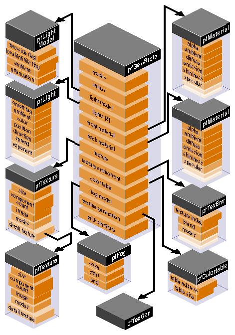
Figure 10-3 diagrams the conceptual structure of a pfGeoState.
Rendering to the graphics hardware requires a window. A window is an allocated area of the screen with associated framebuffer resources. The X window system manages the use of shared resources amongst the different windows. Windows can be requested directly from an X window server. With a bit of interfacing, both IRIS GL and OpenGL graphics contexts can render into X windows. An X window with an IRIS GL graphics context is called a mixed model IRIS GL (GLX) window. An X window with an OpenGL graphics context is called an OpenGL/X window. An X window can only have one graphics context at a time rendering to it. IRIS GL supports a third option: pure IRIS GL windows. Pure IRIS GL windows are convenient and flexible for rendering purposes but can not be used as X windows in X applications. If, for example, you want to put your rendering window inside a larger Motif window, you will need an X window. Libpr provides utilities to shield you from the differences between the different types of windows and guide you in your dealings with the window system. Applications that use the IRIS Performer window utilities can be completely portable between IRIS GL and OpenGL and sill have the option of using pure IRIS GL windows if desired when running in IRIS GL. You'll be able to use your windows in X applications, or direct your rendering to a pre-created window. The libpr windowing support centers around the pfWindow.
pfWindows are structures for managing any of the different kinds of windows and associated pfState. pfWindows provide an efficient windowing interface between your application and the window system. pfWindows shield you from the functional and performance differences between the different graphics libraries and the different window system interfaces and allow you to configure, manipulate, and query IRIS GL, IRIS GL mixed model (GLX), and OpenGL/X windows through a GL and window system independent interface. pfWindows also keep track of your graphics state: they include a pfState which is automatically initialized when you open a window, and switched for you when you change windows.
IRIS Performer will automatically configure and initialize your window so that it will be ready to start rendering efficiently. In the simplest case, pfWindows make creating a graphics application that can run on any Silicon Graphics machine with IRIS GL or OpenGL a snap. pfWindows do not limit your ability to configure any part or all of your windowing environment yourself; you can use the libpr pfWindows to manage your GL windows even if you create and configure the actual windows yourself.
A pfWindow structure is created with pfNewWin(). It can then be immediately opened with pfOpenWin(). Example 10-7 shows the most basic pfWindow operations in libpr program: to open and clear a pfWindow and swap front and back color buffers.
Example 10-7. Opening a pfWindow
int main (void)
{
     pfWindow *win;
     /* Initialize Performer */
     pfInit();
     pfInitState(NULL);

     /* Create and open a Window */
     win = pfNewWin(NULL);
     pfWinName(win, “Hello from IRIS Performer”);
     pfOpenWin();

     /* Rendering loop */
     while (1)
     {
         /* Clear to black and max depth */
         pfClear(PFCL_COLOR | PFCL_DEPTH, NULL);
         ...
         pfSwapWinBuffers(win);
     }
}
|
The pfWindow in Example 10-7 will have the following configuration:
| Window system interface |
| |
| Screen: | The pfWindow will open a window on the screen specified by the DISPLAY environment variable, or else on screen 0. | |
| Position and size: |
| |
| Framebuffer configuration: |
| |
| Libpr state: | A pfState will be created and initialized with all modes disabled and no attributes set. | |
| Graphics state: | The pfWindow will be in RGBA color mode with subpixel vertex positioning, depth testing and viewport clipping enabled. The Viewing projection will be a two-dimensional one-one orthographic mapping from eye coordinates to window coordinates with distances to near and far clipping planes -1 and 1, respectively. The model matrix will be the current matrix and will be initialized to the identity matrix. |
Typically, pfWindows go through a bit more initialization than that of Example 10-7. The type of pfWindow type, set with pfWinType() is a bitmask that selects the window system interface and the type of rendering window. The default window type is a normal graphics rendering window and is pure IRIS GL under IRIS GL operation and X under OpenGL. operation. Table 10-19 lists the possible selectors that can be OR-ed together for specification of the window type.
Table 10-19. pfWinType() Tokens
The selection of screen can be done explicitly with pfWinScreen(), or implicitly by opening a connection to the window system using pfOpenScreen() with the desired screen as the default screen. A window system connection can communicate with any screen on the system; the default screen only determines the screen for windows that do not have a screen explicitly set for them. Only one window system connection should be opened for a process. See “Communicating with the Window System” later in this section for details on efficient interaction with the window system.
The position and/or size, is set with pfWinOriginSize(). If the x and y components of the origin are (-1), the window will open with position undefined for the user to place. If the x or y components of the size are (-1), the window will open with both position and size undefined (the default) for the user to place and stretch. The X window manager may override negative origins and place the window at (0,0). If the window is already opened when pfWinOriginSize() is called, the window will be reconfigured to the specified origin and size upon the next pfSelectWin(). Similarly, pfWinFullScreen() will cause a window to open as full screen or to become full screen upon the next call to pfSelectWin(). A full screen window will have its border automatically removed so that the drawing area truly gets the full rendering surface. The routines for querying the position and size work a bit differently than the pattern established by the rest of libpr get and set pairs of routines. This is because a user may change the origin or size independently of the program and under certain conditions, querying the true current X window size and origin can be expensive. pfGetWinOrigin() and pfGetWinSize() will always be fast and will return the last explicitly set origin and size, such as by pfOpenWin(), pfWinOriginSize(), or pfWinFullScreen(). If the window origin or size has been changed, but not through a pfWindow routine, the values returned by pfGetWinOrigin() and pfGetWinSize() may not be correct. pfGetWinCurOriginSize() will return an accurate size and origin relative to the pfWindow parent. For pure IRIS GL windows, this will also be reasonably fast; however, for X windows, it will be expensive and should not be done in real-time situations. The parent of an IRIS GL window is always the screen, but not so with X windows. pfGetWinCurScreenOriginSize() will return the size and the screen-relative origin of the pfWindow. If the pfWindow is an X window, this command will be quite expensive and is not recommended accept for rare use or initialization purposes.
pfPipeWindows, discussed in Chapter 4, “Setting Up the Display Environment,” take advantage of the multiprocessed libpf environment to always be able to return an accurate window size and origin relative to the window parent. A process separate from the rendering process is by the window manager of changes in the pfPipeWindow's size in an efficient manner without impacting the window system or the rendering process. However, even for pfPipeWindows, getting a screen-relative origin can be an expensive operation.
 | Tip: Users are strongly encouraged to write programs that are window-relative and do not depend on knowing the current exact location of a window relative to its parent or screen. |
IRIS Performer provides a default framebuffer configurations for the current graphics hardware platform for the standard window types: normal rendering, statistics (stats), and overlay. You may want to define your own framebuffer configuration, such as single-buffered, stereo, etc. You can use utilities in libpr to help you with this task, or create your own framebuffer configuration structure with X utilities, or even create the window yourself and apply it to the pfWindow. pfOpenWin() will respect any specified framebuffer configuration. Additionally, pfOpenWin() uses any window or graphics context that is assigned to it and only creates what is undefined.
pfWinFBConfigAttrs() can be used to specify an array of framebuffer attribute tokens listed in Table 10-20. The tokens are exactly like the OpenGL/X tokens and the same attribute list can be used for all window types: pure IRIS GL, mixed model IRIS GL, and OpenGL/X windows. Note that if an attribute array is specified, the tokens modify configuration with no attributes set, not the default IRIS Performer framebuffer configuration.
Table 10-20. pfWinFBConfigAttrs() Tokens
You may get back a framebuffer configuration that is better than the one you requested. IRIS Performer will give you back the maximum framebuffer configuration that meets your request that will not add any serious performance degradations. There are specific machine dependent instances where when possible, for performance reasons, we do limit the framebuffer configuration. See the pfChooseWinFBConfig() reference page for the specific details.
If you desire more control over the exact framebuffer configuration of your pfWindow, you have several options. For pure IRIS GL windows you can make GL framebuffer configuration calls, such as RGBsize(), zbsize(), and mssize(), directly. You can tell IRIS Performer to not do any window configuration by setting an empty attribute array. For X windows you can provide the appropriate framebuffer description for the current GL operation to the pfWindow using pfWinFBConfig(). X uses visuals to describe available framebuffer configurations. You can select the visual for your window and set it on the pfWindow with pfWinFBConfig(). XVisualInfo pointer with XGetVisualInfo() will return a list of all visuals on the system and you can search through them to find the appropriate configuration.
libpr also offers utilities for creating framebuffer configurations (pfFBConfig) independently of a pfWindow. pfChooseFBConfig() takes an attribute array of tokens from Table 10-20 and will return a pfFBConfig structure that can be used with your pfWindows, or with X Windows created outside of libpr, such as with Motif.
You can use pfQuerySys() to query particular framebuffer resources in the current hardware configuration and then use pfQueryWin() to query your resulting framebuffer configuration.
There is a special utility for supporting mixed model IRIS GL (GLX) windows. GLX windows use a special attribute array returned by GLXgetconfig() and expected by GLXlink() for creating a framebuffer configuration and graphics window. You can set and get this special GL-dependent attribute array with pfWinFBConfigData() and pfGetWinFBConfigData(), respectively. This configuration array is useful for hooking up GLX windows with X windows from other toolkits or with Motif. Under OpenGL operation, pfWinFBConfigData() just expects a configuration attribute array appropriate for glXChooseVisual() or pfChooseWinFBConfig().
libpr allows you direct access to the GL and X window handles, or to create your own windows and set them on the pfWindow.
You can create your own windows (and/or in the case of OpenGL/X, graphics contexts) and set them on the pfWindow. You can then call pfOpenWin() to make sure everything is hooked up correctly, apply any specified origin and size, and to initialize your IRIS Performer state. Under pure IRIS GL operation, a window and a graphics context are the same thing. A pure IRIS GL window is created with the winopen() command and can be assigned to the pfWindow with pfWinWSDrawable(), or pfWinGLCxt().
pfOpenWin() will automatically call pfInitGfx() and will automatically create a new pfState for your window. If you have your own window management and do not call pfOpenWin() then you should definitely call pfInitGfx() to initialize the window's graphics state for IRIS Performer rendering and you will also need to call pfNewState() to create a pfState for IRIS Performer's state management.
For X windows, IRIS Performer maintains two windows and a graphics context. The top level X window is the one that placed on the screen and is the one that you should use in your application for selecting X events. This top level window is very lightweight and has minimal resources allocated to it. IRIS Performer then maintains a separate X window that is a child of the parent X window and is the one that is attached to the graphics context. This allows you to select different framebuffer resources for the same drawing area by just selecting a different graphics window and graphics context pair for the parent X window. pfWindows directly support this functionality and this is discussed in the next section, “Manipulating a pfWindow“. Finally, with OpenGL, you may choose to draw to a different X Drawable than a window. X windows are created with the X function XCreateWindow(). Mixed model IRIS GL windows have an X window serve as both the graphics drawable and the GL context. OpenGL graphics contexts are created with glXCreateContext(). The parent X Window can be set with pfWinWSWindow(), the graphics window or X Drawable is set with pfWinWSDrawable(), and the OpenGL graphics context is set with pfWinGLCxt(). For compatibility between GLs, IRIS Performer defines the following GL and Window System independent types defined in Table 10-21 If you create your own window but want to use pfQueryWin() you must also provide the framebuffer configuration information with pfWinFBConfig() and pfWinFBConfigData() for OpenGL and GLX respectively. pfQueryWin() uses the internally stored visual, and in the case of GLX, the attribute array given to the GLX call GLXlink(). .
Table 10-21. Window System Types
pfWS Type | X Type | pfWindow Set/Get Routine |
|---|---|---|
pfWSWindow | Window | |
pfWSDrawable | Drawable | |
pfGLContext | IRIS GL: | |
pfFBConfig | XVisualInfo* | |
pfWSConnection | Display |
Windows are opened with pfOpenWin() and closed with pfCloseWin(). When a window is closed, its graphics context is deleted. If you have multiple windows, you select the window to draw to with pfSelectWin(). Windows can be dynamically resized with the same sizing commands discussed previously for setting up the window.
IRIS Performer supports multiple framebuffer configurations for the same drawing area in a GL independent fashion with alternate configuration windows. An IRIS Performer alternate configuration window has the same window parent (pfWinWSWindow()) but may have a different drawable and graphics context. There are standard alternate configuration windows for overlay and statistics windows that can be automatically created upon demand. For pure IRIS GL, alternate configuration windows must have their graphics context be the same as the base window. The rest of this section assumes the use of X windows in either GLX or OpenGL/X.
An alternate configuration window is created as a full pfWindow and is an alternate configuration window by virtue of being given to a base window in a pfList of alternate configuration windows, or being directly assigned as one of the standard alternate configuration windows with either of pfWinOverlayWin() or pfWinStatsWin(). A pfWindow may be an alternate configuration window of only one base window at a time; alternate configuration windows may not be instanced between base windows. The sharing of window attributes between alternate configuration windows, such as the parent X window and GL objects (for OpenGL windows), must be set with pfWinShare() on the base window and applied to the alternate configuration windows with pfAttachWin(). You select the desired alternate configuration window to draw into with pfWinIndex() and provide an index into your alternate configuration window list or one of the standard indices (PFWIN_GFX_WIN, PFWIN_OVERLAY_WIN, or PFWIN_STATS_WIN). PFWIN_GFX_WIN is the default window index and selects the base window. If the alternate configuration window has not been opened, it will be opened automatically upon being selected for rendering. Example 10-9 demonstrates creating a pfWindow using the default overlay window. The graphics drawable and graphics context of an alternate configuration window of a pfWindow can be closed with pfCloseWinGL(). This can be called on the base window, in which case the active alternate configuration window's GL window and context will be closed, or it can be called on the alternate configuration window pfWindow directly. The main parent window will remain on the screen and a new alternate configuration window can be applied to it or pfOpenWin() can be called to create a new graphics window and context.
There are some modes you can set that can effect the general look and behavior of your window and alternate configuration windows. These boolean modes can be individually set and changed at any time with pfWinMode() and the tokens in Table 10-22
Table 10-22. pfWinMode() Tokens
You can communicate with a local or remote window server by means of a window system connection, a pfWSConnection (in X, also known as a Display connection). You can use your pfWSConnection for selecting X events for your window, as is demonstrated in Example 10-11.
Libpr offers several utilities for creating a connection to a window server. A given connection can communicate with any screen managed by that window server so usually a process only needs one connection. A process should not share the connection of another process, so you will need a connection per process. Typically, there is exactly one window server on a machine but that is not required. Libpr maintains a pfWSConnection for the current process. By default, this connection obeys the setting of the DISPLAY environment variable which can point to a window server on a local or a remote machine. The current connection can be requested with pfGetCurWSConnection(), and can be set with pfSelectWSConnection(). It is recommended that whenever possible, this connection be used to limit the total number of open connections. pfOpenScreen() is a convenient mechanism for opening a connection with a specified default screen. pfOpenWSConnection() allows you to specify the exact name specifying the desired target for the connection. Both pfOpenScreen() and pfOpenWSConnection() allow you to specify if you would like the new connection to automatically be made the current libpr pfWSConnection; this is recommended.
Example 10-8 demonstrates creating a window that will support a desired fill statistics configuration. This example is taken from the sample program /usr/share/Performer/src/pguide/libpr/C/fillstats.c. Statistics are the topic of Chapter 12, “Statistics.”
Example 10-8. Creating a Statistics Window
int main (void)
{
    pfWindow *win;
    int bits, sten;
    /* Initialize Performer */
    pfInit();
    pfInitState(NULL);

     /* set up number of bits needed for stats before
      * window is made so that it will have the right number
      */
     pfQuerySys(PFQSYS_MAX_STENCIL_BITS,&sten);
     bits = PF_MIN2(4, sten);
     pfStatsHwAttr(PFSTATSHW_FILL_DCBITS, bits);

     /* Initialize GL */
     win = pfNewWin(NULL);
     pfWinOriginSize(win, 100, 100, 500, 500);
     pfWinName(win, “Iris Performer”);
     pfWinType(win, PFWIN_TYPE_X | PFWIN_TYPE_STATS );
     pfOpenWin(win);
     ....
}
|
Example 10-9 demonstrates the creation of a window with a default overlay window.
Example 10-9. Using the Default Overlay Window
int main (void)
{
    pfWindow *win, *over;
    /* Initialize Performer */
    pfInit();
    pfInitState(NULL);

    /* Initialize the window. */
     win = pfNewWin(NULL);
     pfWinOriginSize(win, 100, 100, 500, 500);
     pfWinName(win, “Iris Performer”);
     pfWinType(win, PFWIN_TYPE_X);
     pfWinMode(win, PFWIN_HAS_OVERLAY, 1);
     pfOpenWin(win);
     /* First select and draw into the overlay window */
     pfWinIndex(win, PFWIN_OVERLAY_WIN);
     /* Select causes the index to be applied */
     pfSelectWin(win);
     ...
     /* Then select the main gfx window */
     pfWinIndex(win, PFWIN_GFX_WIN);
     pfSelectWin(win);
     ...
}
|
Example 10-10 demonstrates creating a custom overlay window and is taken from the sample program /usr/share/Performer/src/pguide/libpr/C/winfbconfig.c.
Example 10-10. Creating a Custom Overlay Window
static int OverlayAttrs[] = {
 PFFB_LEVEL, 1, /* Level 1 indicates overlay visual */
 PFFB_BUFFER_SIZE, 8,
 None,
};

int main (void)
{
    pfWindow *win, *over;
    /* Initialize Performer */
    pfInit();
    pfInitState(NULL);

    /* Initialize the window. */
     win = pfNewWin(NULL);
     pfWinOriginSize(win, 100, 100, 500, 500);
     pfWinName(win, “Iris Performer”);
     pfWinType(win, PFWIN_TYPE_X);
     pfWinMode(win, PFWIN_HAS_OVERLAY, 1);

     over = pfNewWin(NULL);
     pfWinName(over, “Iris Performer Overlay”);
     pfWinType(over, PFWIN_TYPE_X | PFWIN_TYPE_OVERLAY);
     /* See if we can get the desired overlay visual */
     if (!(pfChooseWinFBConfig(over, OverlayAttrs)))
	         pfNotify(PFNFY_NOTICE, PFNFY_PRINT,
            		“pfChooseWinFBConfig failed for OVERLAY win”);
     pfOpenWin(win);
     /* First select and draw into the overlay window */
     pfWinIndex(win, PFWIN_OVERLAY_WIN);
     /* Select causes the index to be applied */
     pfSelectWin(win);
     ...
     /* Then select the main gfx window */
     pfWinIndex(win, PFWIN_GFX_WIN);
     pfSelectWin(win);
     ...
}
|
Example 10-11 demonstrates the selection of X input events on a pfWindow. This example is taken from /usr/share/Performer/src/pguide/libpr/C/hlcube.c. See the /usr/share/Performer/src/pguide/libpf/C/complex.c sample program for a detailed example of using either GL or forked X input on pfWindows.
Example 10-11. pfWindows and X Input
    pfWSConnection Dsp;

void main (void)
{
    pfWindow *win;
    pfWSWindow xwin;

    /* Initialize Performer */
    pfInit();
    pfInitState(NULL);

    /* Initialize the window. */
     win = pfNewWin(NULL);
     pfWinOriginSize(win, 100, 100, 500, 500);
     pfWinName(win, “Iris Performer”);
     pfWinType(win, PFWIN_TYPE_X);
     pfOpenWin(win);
     ...
     /* set up X input event handling on pfWindow */
     Dsp = pfGetCurWSConnection();
     xwin = pfGetWinWSWindow(win);
     XSelectInput(Dsp, xwin, KeyPressMask );
     XMapWindow(Dsp, xwin);
     XSync(Dsp,FALSE);
     ...
     do_events(win);
}
static void
do_events(pfWindow *win)
{
    while (1) {
	    while (XPending(dsp))
	    {
	         XEvent event;
	         XNextEvent(Dsp, &event);
	         switch (event.type)
	         {
         case KeyPress:
          ....
          }
     }
}
|
Example 10-12 shows how to make a colored cube. This example is derived from source code in /usr/share/Performer/src/pguide/libpr/C/colorcube.c.
Example 10-12. Constructing a Colored Cube With libpr
/*
 * colorcube.c		 - routine for constructing colored cube geoset
 */

#include <Performer/pr.h>
#include <stdlib.h>

#define	CUBE_SIZE		1.0f

pfGeoSet*
MakeColorCube(void *arena)
{
    pfGeoSet *gset;
    pfGeoState *gst;

    pfVec4 *scolors;
    pfVec3 *snorms, *scoords;
    ushort *nindex, *vindex, *cindex;

    /*
     * Data arrays to be passed to pfGSetAttr should be
     * allocated from heap memory...
     */
     scolors = (pfVec4 *)pfMalloc(4 * sizeof(pfVec4), arena);
     pfSetVec4(scolors[0], 1.0f, 0.0f, 0.0f, 0.5f);
     pfSetVec4(scolors[1], 0.0f, 1.0f, 0.0f, 0.5f);
     pfSetVec4(scolors[2], 0.0f, 0.0f, 1.0f, 0.5f);
     pfSetVec4(scolors[3], 1.0f, 1.0f, 1.0f, 0.5f);

     snorms = (pfVec3 *)pfMalloc(6 * sizeof(pfVec3), arena);
     pfSetVec3(snorms[0], 0.0f, 0.0f, 1.0f);
     pfSetVec3(snorms[1], 0.0f, 0.0f, -1.0f);
     pfSetVec3(snorms[2], 0.0f, 1.0f, 0.0f);
     pfSetVec3(snorms[3], 0.0f, -1.0f, 0.0f);
     pfSetVec3(snorms[4], 1.0f, 0.0f, 0.0f);
     pfSetVec3(snorms[5], -1.0f, 0.0f, 0.0f);

     scoords = (pfVec3 *)pfMalloc(8 * sizeof(pfVec3), arena);
     pfSetVec3(scoords[0], -CUBE_SIZE, -CUBE_SIZE,
                            CUBE_SIZE);
     pfSetVec3(scoords[1], CUBE_SIZE, -CUBE_SIZE, CUBE_SIZE);
     pfSetVec3(scoords[2], CUBE_SIZE, CUBE_SIZE, CUBE_SIZE);
     pfSetVec3(scoords[3], -CUBE_SIZE, CUBE_SIZE, CUBE_SIZE);
     pfSetVec3(scoords[4], -CUBE_SIZE, -CUBE_SIZE,
                           -CUBE_SIZE);
     pfSetVec3(scoords[5], CUBE_SIZE, -CUBE_SIZE,
                          -CUBE_SIZE);
     pfSetVec3(scoords[6], CUBE_SIZE, CUBE_SIZE, -CUBE_SIZE);
     pfSetVec3(scoords[7], -CUBE_SIZE, CUBE_SIZE,
	                           -CUBE_SIZE);

     nindex = (ushort *)pfMalloc(6 * sizeof(ushort), arena);
     nindex[0] = 0; nindex[1] = 5; nindex[2] = 1;
     nindex[3] = 4; nindex[4] = 2; nindex[5] = 3;

     vindex = (ushort *)pfMalloc(24 * sizeof(ushort), arena);
     vindex[0]  = 0; vindex[1]  = 1; /* front */
     vindex[2]  = 2; vindex[3]  = 3;
     vindex[4]  = 0; vindex[5]  = 3; /* left */
     vindex[6]  = 7; vindex[7]  = 4;
     vindex[8]  = 4; vindex[9]  = 7; /* back */
     vindex[10] = 6; vindex[11] = 5;
     vindex[12] = 1; vindex[13] = 5; /* right */
     vindex[14] = 6; vindex[15] = 2;
     vindex[16] = 3; vindex[17] = 2; /* top */
     vindex[18] = 6; vindex[19] = 7;
     vindex[20] = 0; vindex[21] = 4; /* bottom */
     vindex[22] = 5; vindex[23] = 1;

     cindex = (ushort *)pfMalloc(24 * sizeof(ushort), arena);
     cindex[0] = 0; cindex[1] = 1;
     cindex[2] = 2; cindex[3] = 3;
     cindex[4] = 0; cindex[5] = 1;
     cindex[6] = 2; cindex[7] = 3;
     cindex[8] = 0; cindex[9] = 1;
     cindex[10] = 2; cindex[11] = 3;
     cindex[12] = 0; cindex[13] = 1;
     cindex[14] = 2; cindex[15] = 3;
     cindex[16] = 0; cindex[17] = 1;
     cindex[18] = 2; cindex[19] = 3;
     cindex[20] = 0; cindex[21] = 1;
     cindex[22] = 2; cindex[23] = 3;

     /* Allocate the pfGeoSet out of the same arena. */
     gset = pfNewGSet(arena);

     /*
      * set the coordinate, normal and color arrays
      * and their corresponding index arrays
      */
     pfGSetAttr(gset, PFGS_COORD3, PFGS_PER_VERTEX,
                scoords, vindex);
     pfGSetAttr(gset, PFGS_NORMAL3, PFGS_PER_PRIM,
                norms, nindex);
     pfGSetAttr(gset, PFGS_COLOR4, PFGS_PER_VERTEX,
                scolors, cindex);
     pfGSetPrimType(gset, PFGS_QUADS);
     pfGSetNumPrims(gset, 6);

     /*
      * create a new geostate from shared memory,
      * disable texturing and enable transparency
      */
     gst = pfNewGState(arena);
     pfGStateMode(gst, PFSTATE_ENTEXTURE, 0);
     pfGStateMode(gst, PFSTATE_TRANSPARENCY, 1);

     pfGSetGState(gset, gst);
     return gset;
}
|
Example 10-13 demonstrates construction of a textured cube. This example can be found in the file /usr/share/Performer/src/pguide/libpr/C/texcube.c.
Example 10-13. Constructing a Textured Cube With libpr
/*
 * texcube.croutine for constructing a textured cube geoset
 */

#include <Performer/pr.h>

#define CUBE_SIZE1.0f

pfGeoSet*
MakeTexCube(void *arena)
{
     pfGeoSet *gset;
     pfGeoState *gst;
     pfTexture *tex;
     pfTexEnv *tenv;
     pfVec3 *verts, *norms;
     pfVec2 *tcoords;
     ushort *vindex, *nindex, *tindex;

     /*
     * Data arrays to be passed to pfGSetAttr should be
     * allocated from heap memory...
     /
     verts = (pfVec3 *)pfMalloc(8 * sizeof(pfVec3), arena);
     pfSetVec3(verts[0], -CUBE_SIZE, -CUBE_SIZE, CUBE_SIZE);
     pfSetVec3(verts[1], CUBE_SIZE, -CUBE_SIZE, CUBE_SIZE);
     pfSetVec3(verts[2], CUBE_SIZE, CUBE_SIZE, CUBE_SIZE);
     pfSetVec3(verts[3], -CUBE_SIZE, CUBE_SIZE, CUBE_SIZE);
     pfSetVec3(verts[4], -CUBE_SIZE, -CUBE_SIZE, -CUBE_SIZE);
     pfSetVec3(verts[5], CUBE_SIZE, -CUBE_SIZE, -CUBE_SIZE);
     pfSetVec3(verts[6], CUBE_SIZE, CUBE_SIZE, -CUBE_SIZE);
     pfSetVec3(verts[7], -CUBE_SIZE, CUBE_SIZE, -CUBE_SIZE);

     vindex = (ushort *)pfMalloc(24 * sizeof(ushort), arena);
     vindex[0]  = 0; vindex[1]  = 1;  /* front */
     vindex[2]  = 2; vindex[3]  = 3;
     vindex[4]  = 0; vindex[5]  = 3;  /* left */
     vindex[6]  = 7; vindex[7]  = 4;
     vindex[8]  = 4; vindex[9]  = 7;  /* back */
     vindex[10] = 6; vindex[11] = 5;
     vindex[12] = 1; vindex[13] = 5;  /* right */
     vindex[14] = 6; vindex[15] = 2;
     vindex[16] = 3; vindex[17] = 2;  /* top */
     vindex[18] = 6; vindex[19] = 7;
     vindex[20] = 0; vindex[21] = 4;  /* bottom */
     vindex[22] = 5; vindex[23] = 1;

     norms = (pfVec3 *)pfMalloc(6 * sizeof(pfVec3), arena);
     pfSetVec3(norms[0], 0.0f, 0.0f, 1.0f);
     pfSetVec3(norms[1], 0.0f, 0.0f, -1.0f);
     pfSetVec3(norms[2], 0.0f, 1.0f, 0.0f);
     pfSetVec3(norms[3], 0.0f, -1.0f, 0.0f);
     pfSetVec3(norms[4], 1.0f, 0.0f, 0.0f);
     pfSetVec3(norms[5], -1.0f, 0.0f, 0.0f);

     nindex = (ushort *)pfMalloc(6 * sizeof(ushort), arena);
     nindex[0] = 0; nindex[1] = 5; nindex[2] = 1;
     nindex[3] = 4; nindex[4] = 2; nindex[5] = 3;

     tcoords = (pfVec2 *)pfMalloc(4 * sizeof(pfVec2), arena);
     pfSetVec2(tcoords[0], 0.0f, 0.0f);
     pfSetVec2(tcoords[1], 1.0f, 0.0f);
     pfSetVec2(tcoords[2], 1.0f, 1.0f);
     pfSetVec2(tcoords[3], 0.0f, 1.0f);

     tindex = (ushort *)pfMalloc(24 * sizeof(ushort), arena);
     tindex[0]  = 0; tindex[1]  = 1;
     tindex[2]  = 2; tindex[3]  = 3;
     tindex[4]  = 0; tindex[5]  = 1;
     tindex[6]  = 2; tindex[7]  = 3;
     tindex[8]  = 0; tindex[9]  = 1;
     tindex[10] = 2; tindex[11] = 3;
     tindex[12] = 0; tindex[13] = 1;
     tindex[14] = 2; tindex[15] = 3;
     tindex[16] = 0; tindex[17] = 1;
     tindex[18] = 2; tindex[19] = 3;
     tindex[20] = 0; tindex[21] = 1;
     tindex[22] = 2; tindex[23] = 3;

     /* Allocate the pfGeoSet out of the same arena */
     gset = pfNewGSet(arena);

     /*
      * set the coordinate, normal and color arrays
      * and their corresponding index arrays
      */
     pfGSetAttr(gset, PFGS_COORD3, PFGS_PER_VERTEX,
                      verts, vindex);
     pfGSetAttr(gset, PFGS_NORMAL3, PFGS_PER_PRIM,
                      norms, nindex);
     pfGSetAttr(gset, PFGS_TEXCOORD2, PFGS_PER_VERTEX,
                      tcoords, tindex);
     pfGSetPrimType(gset, PFGS_QUADS);
     pfGSetNumPrims(gset, 6);

     /*
      * create a geostate from the arena, enable
      * texturing (in case that's not the default), and
      * set the geostate for this geoset
      */
     gst = pfNewGState(arena);
     pfGStateMode(gst, PFSTATE_ENTEXTURE, 1);
     pfGSetGState(gset, gst);

     /*
      * create a new texture from shared memory,
      * load a texture file and add texture to geostate
      */
     tex = pfNewTex(arena);
      pfLoadTexFile(tex, “brick.rgba”);
      pfGStateAttr(gst, PFSTATE_TEXTURE, tex);

      /* Create a new texture environment from the arena. */
      tenv = pfNewTEnv(arena);
      /* Decal the texture since the geoset has no color to
       * modulate.
       */
      pfTEnvMode(tenv, PFTE_DECAL);
      /* set the texture environment for this pfGeoState *./
      pfGStateAttr(gst, PFSTATE_TEXENV, tenv);

      return gset;
}
|
This section describes routines that manage nongraphic tasks such as clocks, memory, I/O, and error handling.
IRIS Performer provides clock support for timing operations.
IRIS Performer provides access to a high-resolution clock that reports elapsed time in seconds. To start a clock, call pfInitClock() with the initial time in seconds—usually 0.0—as the parameter. Subsequent calls to pfInitClock() reset the time to whatever value you specify. To read the time, call pfGetTime(). This function returns a double-precision floating point number representing the seconds elapsed from initialization added to the latest reset value.
The resolution of the clock depends on your system type and configuration. In most cases, the resolved time interval is under a microsecond, and so is much less than the time required to process the pfGetTime() call itself. Exceptions are older Power Series™ machines with IO2 boards and some Personal Iris™ computers. You can use the IRIX hinv command to see whether your Power Series system has an IO2 board or an IO3 board installed. Onyx, Crimson™, Indigo2™, Indigo\xb8 ®, and Indy™ systems all provide submicrosecond resolution. On a machine that uses a fast hardware counter, the first invocation of pfInitClock() forks off a process that periodically wakes up and checks the counter for wrapping. This additional process can be suppressed using pfClockMode().
If IRIS Performer cannot find a fast hardware counter to use, it defaults to the time-of-day clock, which typically has a resolution between one and ten milliseconds. This clock resolution can be improved by using fast timers. See the ftimer(1) reference page for more information on fast timers.
By default, processes forked after the first call to pfInitClock() share the same clock and will all see the results of any subsequent pfInitClock(). All such processes receive the same time.
Unrelated processes can share the same clock by calling pfClockName() with a clock name before calling pfInitClock(). This provides a way to name and reference a clock. By default, unrelated processes don't share clocks.
The video refresh counter (VClock) is a counter that increments once for every vertical retrace interval. There is one VClock per system. In systems where multiple graphics pipelines are present, but not genlocked (synchronized, see the setmon(3) reference page), screen 0 is used as the source for the counter. A process can be blocked until a certain count, or the count modulo some value (usually desired number of video fields per frame) is reached.
Table 10-23 lists and describes the pfVClock routines.
Table 10-23. pfVClock Routines
Function | Action |
|---|---|
Initialize the clock to a value. | |
Get the current count. | |
Block the calling process until a count is reached. |
When using pfVClockSync(), the calling routine is blocked until the current count modulo rate is offset. The VClock functions can be used to synchronize several channels or pipelines.
You can use IRIS Performer memory-allocation functions to allocate memory from the heap, from shared memory, and from datapools.
Table 10-24 lists and describes the IRIS Performer shared memory routines.
Table 10-24. Memory Allocation Routines
Function | Action |
|---|---|
Create arenas for shared memory and semaphores. | |
Specify the size of a shared memory arena. | |
Get the shared memory arena pointer. | |
Get the shared semaphore/lock arena pointer. | |
Allocate from an arena or the heap. | |
Release memory allocated with pfMalloc(). |
pfMalloc() can allocate memory either from the heap or from a shared memory arena. Multiple processes can access memory allocated from a shared memory arena, whereas memory allocated from the heap is visible only to the allocating process. Pass a shared-memory arena pointer to pfMalloc() to allocate memory from the given arena. pfGetSharedArena() returns the pointer for the arena allocated by pfInitArenas(), or NULL if the given memory was allocated from the heap. Alternately, an application can create its own shared memory arena; see the acreate(3P) reference page for information on how to create an arena.
To allocate memory from the heap, pass NULL to pfMalloc() instead of an arena pointer.
Under normal conditions pfMalloc() never returns NULL. If the allocation fails, pfMalloc() generates a pfNotify() of level PFNFY_FATAL, so unless the application has set a pfNotifyHandler(), the application will exit.
Memory allocated with pfMalloc() must be freed with pfFree(), not with the standard C library's free() function. Using free() with data allocated by pfMalloc() will have devastating results.
Memory allocated with pfMalloc() has a reference count (see“pfDelete() and Reference Counting” in Chapter 2 for information on reference counting). For example, if you use pfMalloc() to create attribute and index arrays, which you then attach to pfGeoSets using pfGSetAttr(), IRIS Performer automatically tracks the reference counts for the arrays, letting you delete the arrays much more easily than if you create them without pfMalloc(). All the reference-counting routines (including pfDelete()) work with data allocated using pfMalloc(). Note, however, that pfFree() doesn't check the reference count before freeing memory; use pfFree() only when you're sure the data you're freeing isn't referenced.
pfGetSize() returns the size in bytes of any data allocated by pfMalloc(). Since the size of such data is known, pfCopy() also works on allocated data.
Although pfMalloc()-allocated data behaves in many ways like a pfObject (see “Nodes” in Chapter 5), such data doesn't contain a user data pointer. This omission avoids requiring an extra word to be allocated with every piece of pfMalloc() data.
pfInitArenas() creates two arenas, one for the allocation of shared memory with pfMalloc() and one for the allocation of semaphores and locks with usnewlock() and usnewsema(). The arenas are visible to all processes forked after pfInitArenas() is called.
Applications using libpf don't need to explicitly call pfInitArenas(), since it's invoked by pfInit().
The shared memory arena can be allocated by memory-mapping either swap space (/dev/zero, the default) or an actual disk file (in the directory specified by the environment variable PFTMPDIR). The latter requires sufficient disk space for as much of the shared memory arena as will be used, and disk files are somewhat slower than swap space in allocating memory.
By default, IRIS Performer creates a large shared memory arena of 256 MB. Though this approach makes large numbers appear when you run ps(1), it doesn't consume any substantial resources, since swap or file system space isn't actually allocated until accessed (that is, until pfMalloc() is called).
Because IRIS Performer cannot increase the size of the arena after initialization, an application requiring a larger shared memory arena should call pfSharedArenaSize() to specify the maximum amount of memory to be used. Arena sizes as large as 1.7 GB are usually acceptable; but you may need to set the virtual-memory-use and memory-use limits, using the shell limit command or setrlimit(), to allow your application to use that much memory.
An application requiring lockable pieces of memory should consider using pfDataPools, described below. Alternatively, when a lock or semaphore is required in an application that has called pfInitArenas(), you can call pfGetSemaArena() to get an arena pointer, and you can allocate locks or semaphores using usnewlock() and usnewsema().
Datapools, or pfDataPools, are also a form of shared memory, but they work differently from pfMalloc(). Datapools allow unrelated processes to share memory and lock out access to eliminate data contention. They also provide a way for one process to access memory allocated by another process.
Any process can create a datapool by calling pfCreateDPool() with a name and byte size for the pool. If an unrelated process needs access to the datapool, it must first put the datapool in its address space by calling pfAttachDPool() with the name of the datapool. The datapool must reside at the same virtual address in all processes. If the default choice of an address causes a conflict in an attaching process pfAttachDPool() will fail. To avoid this pfDPoolAttachAddr() can be called before pfCreateDPool() to specify a different address for the datapool.
Any attached process can allocate memory from the datapool by calling pfDPoolAlloc(). Each block of memory allocated from a datapool is assigned an ID so that other processes can retrieve the address using pfDPoolFind().
Once you've allocated memory from a datapool, you can lock the memory chunk (not the entire pfDataPool) by calling pfDPoolLock() before accessing the memory. This locking mechanism works only if all processes wishing to access the datapool memory use pfDPoolLock() and pfDPoolUnlock(). After a piece of memory has been locked using pfDPoolLock(), any subsequent pfDPoolLock() call on the same piece of memory will block until the next time a pfDPoolUnlock() is called for that memory.
pfDataPools are pfObjects, so call pfDelete() to delete them. Calling pfReleaseDPool() unlinks the file used for the datapool—it doesn't immediately free up the memory that was used or prevent further allocations from the datapool; it just prevents processes from attaching to it. The memory is freed when the last process referring to the datapool pfDelete()s it.
A multiprocessed environment often requires that data be duplicated so that each process can work on its own copy of the data without adversely colliding with other processes. pfCycleBuffer is a memory structure which supports this programming paradigm. A pfCycleBuffer consists of one or more pfCycleMemories which are equally-sized memory blocks. The number of pfCycleMemories per pfCycleBuffer is global and is set once with pfCBufferConfig(), and is typically equal to the number of processes accessing the data.
Each process has a global index, set with pfCurCBufferIndex(), which indexes a pfCycleBuffer's array of pfCycleMemories. When each process has a different index (and its own address space), mutual exclusion is ensured if the process limits its pfCycleMemory access to the currently indexed one.
The “cycle” term of pfCycleBuffer refers to its suitability for pipelined multiprocessing environments where processes are arranged in stages like an assembly line and data propagates down one stage of the pipeline each frame. In this situation, the array of pfCycleMemories can be visualized as a circular list. Each stage in the pipeline accesses a different pfCycleMemory and at frame boundaries the global index in each process is advanced to the next pfCycleMemory in the chain. In this way, data changes made in the head of the pipeline are propagated through the pipeline stages by “cycling” the pfCycleMemories.
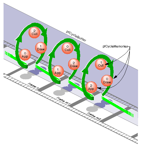
Cycling the memory buffers works if each current pfCycleMemory is completely updated each frame. If this is not the case, buffer cycling will eventually access a “stale” pfCycleMemory whose contents were valid some number of frames ago but are invalid now. pfCycleBuffers manage this by frame-stamping a pfCycleMemory whenever pfCBufferChanged() is called. The global frame count is advanced with pfCBufferFrame() which also copies most recent pfCycleMemories into “stale” pfCycleMemories thereby automatically keeping all pfCycleBuffers current.
A pfCycleBuffer consisting of pfCycleMemories of nbytes size is allocated from memory arena with pfNewCBuffer(nbytes, arena). To initialize all the pfCycleMemories of a pfCycleBuffer to the same data call pfInitCBuffer(). pfCycleMemory is derived from pfMemory so you can use inherited routines like pfCopy, pfGetSize, and pfGetArena() on pfCycleMemories.
While pfCycleBuffers may be used for application data, their primary use is as pfGeoSet attribute arrays, e.g., coordinates or colors. pfGeoSets accept pfCycleBuffers (or pfCycleMemory) references as attribute references and automatically select the proper pfCycleMemory when drawing or intersecting with the pfGeoSet.
| Note: libpf applications need not call pfCBufferConfig() or pfCBufferFrame() since the libpf routines pfConfig() and pfFrame() call these respectively. |
A nonblocking file interface is provided to allow real-time programs access to disk files without affecting program timing. The system calls pfOpenFile(), pfCloseFile(), pfReadFile(), and pfWriteFile() work in an identical fashion to their IRIX counterparts open(), close(), read(), and write().
When pfOpenFile() or pfCreateFile() is called, a new process is created using sproc(), which manages access to the file. Subsequent calls to pfReadFile(), pfWriteFile(), and pfSeekFile() place commands in a queue for the file manager to execute and return immediately. To determine the status of a file operation, call pfGetFileStatus().
IRIS Performer provides a general method for handling errors both within IRIS Performer and in the application. Applications can control error-handling by installing their own error-handling functions. You can also control the level of importance of an error.
Table 10-25 lists and describes the functions for setting notification levels.
Table 10-25. pfNotify Functions
Function | Action |
|---|---|
Install user error-handling function. | |
Set the error-notification level. | |
Generate a notification. |
pfNotify() allows an application to signal an error or print a message that can be selectively suppressed. pfNotifyLevel() sets the notification level to one of the values listed in Table 10-26.
Table 10-26. Error Notification Levels
Token | Meaning |
|---|---|
Always print regardless of notify level | |
Fatal error | |
Serious warning | |
Warning | |
Information and floating point exceptions | |
Debug information | |
Floating point debug information |
The environment variable PFNFYLEVEL can be set to override the value specified in pfNotifyLevel(). Once the notification level is set via PFNFYLEVEL it can not be changed by an application.
Once the notify level is set, only those messages with a priority greater than or equal to the current level are printed or handed off to the user function. Fatal errors cause the program to exit unless the application has installed a handler with pfNotifyHandler().
Setting the notification level to PFNFY_FP_DEBUG has the additional effect of trapping floating point exceptions such as overflows or operations on invalid floating point numbers. It may be a good idea to use a notification level of PFNFY_FP_DEBUG while testing your application, so that you will be informed of all floating-point exceptions that occur.
IRIS Performer provides a mechanism to allow referencing a file via a set of path names. Applications can create a search list of path names in two ways: the PFPATH environment variable and pfFilePath(). (Note that the PFPATH environment variable controls file search paths and has nothing to do with the pfPath data structure.)
Table 10-27 describes the routines for working with pfFilePaths.
Table 10-27. pfFilePath Routines
Routine | Action |
|---|---|
Create a search path. | |
Search for the file using the search path. | |
Supply current search path. |
Pass a search path to pfFilePath() in the form of a colon-separated list of path names. Calling pfFilePath() a second time replaces the current path list rather than appending to it.
The environment variable PFPATH is also a colon-separated list of path names, similar to the PATH variable. pfFindFile() searches the paths in PFPATH first, then those given in the most recent pfFilePath() call; it returns the complete pathname for the file if the file is found. IRIS Performer applications should use pfFindFile() (either directly or through routines such as pfdLoadFile()) to look for input data files.
pfGetFilePath() returns the last search path specified by a pfFilePath() call. It doesn't return the path specified by the PFPATH environment variable—if you want to find out that value, call getenv(3c).