Once you've learned how to create visual simulation applications with IRIS Performer your next task is to import visual databases into those applications. Import and export functions for more than 30 popular database formats are provided with IRIS Performer to ease this effort. This chapter describes the steps involved in creating custom loaders for other data formats and then reviews each of these pre-existing file-loading utilities. Along the way, it also describes several utility functions in the IRIS Performer database utility library that can make the process of database conversion easier for you.
Source code is provided for most of the tools discussed in this chapter. In most cases the loaders are short, easy to understand, and easy to modify. Table 9-1 lists the subdirectories of /usr/share/Performer/src/lib where you can find the source code for the database processing tools.
Table 9-1. Database-Importer Source Directories
Directory Name | Directory Contents |
|---|---|
General database processing tools and utilities | |
Load, convert, and store specific database formats | |
Additional utility functions |
Before you can import a database, you must create it. Some simulation applications create data procedurally; for examples of this approach, see the “Silicon Graphics PHD Format” or “Sierpinski Sponge Format” sections of this chapter. In most cases, however, you must create visual databases manually. Several software packages are available to help with this task, and most such systems facilitate geometric modeling, texture creation, and interactive specification of colors and material properties. Some advanced systems support level-of-detail specification, animation sequences, motion planning for jointed objects, automated roadway and terrain generation, and other specialized functions.
There are several layers of support in IRIS Performer for loading 3-D models and 3-D environments into IRIS Performer run-time scene graphs. In fact, IRIS Performer 2.0 contains the new libpfdu library devoted to the import of data into (and export of data from) IRIS Performer run-time structures. Note that two database exporters have already been written for the Medit and DWB database formats.
At the top level of the API, IRIS Performer provides a standard set of functions to read in files and convert databases of unknown type. This functionality is centered around the notion of a database converter. A database converter is an abstract entity that knows how to perform some or all of a set of database format conversion functions with a particular database format. Moreover, converters must follow certain API guidelines for standard functionality such that they can be easily integrated into IRIS Performer in a run-time environment without IRIS Performer needing any a priori knowledge of a particular converter's existence. This run-time integration is done through the use of dynamic shared object (DSO) libraries.
libpfdu provides the following general routines to operate on 3-D databases.
Table 9-2. libpfdu database converter functions
Function Name | Description |
|---|---|
Load a database file into an IRIS Performer scene graph | |
pfdStoreFile | Store a run-time scene graph into a database file |
Convert an external run-time format into an IRIS Performer scene graph | |
Convert an IRIS Performer scene graph into an external run-time format |
The database loader utility library, libpfdu, provides a convenient function named pfdLoadFile() that can import database files stored in any supported format - see Table 9-6 for a list of supported formats.
Loading database files with pfdLoadFile() is easy. The function prototype is
pfNode *pfdLoadFile(char *fileName); |
pfdLoadFile() tests the filename-extension portion of fileName (the substring starting at the last period in fileName, if any) for one of the format-name codes listed in Table 9-6, then calls the appropriate importer.
The file-format selection process is implemented using dynamic loading of DSOs, which are IRIX Dynamic Shared Objects. This process allows new loaders that are developed as database formats change to be used with IRIS Performer-based applications without requiring recompilation of the IRIS Performer application. The details of the loading process internal to pfdLoadFile() include searching for the named file using the current IRIS Performer file path, extraction of the file-type extension, translation of the extension using a registered alias facility, formation of the DSO name, searching through a list of user-defined and standard directories for that DSO, dynamic loading of the indicated DSO using dlopen(), formation of a loader function name, finding that function within the DSO using dlsym(), and finally, invocation of the loader function.
The loader function name is constructed from two components, a prefix and the loader suffix. The prefix is always “pfdLoadFile_” and the suffix is simply the file extension string. Examples of several complete loader function names are shown in Table 9-3.
Table 9-3. Loader Name Composition
File Extension | Loader Function Name |
|---|---|
dwb | pfdLoadFile_dwb |
flt | pfdLoadFile_flt |
medit | pfdLoadFile_medit |
obj | pfdLoadFile_obj |
Several shell environment variables are used in the loader location process. These are PFLD_LIBRARY_PATH, LD_LIBRARY_PATH, and PFHOME. Confusion about loader locations can be resolved by consulting the sources mentioned above to understand the use of these directory lists and reading the following section, “Database Loading Details”. When the pfNotifyLevel is set to PFNFY_DEBUG or greater, the DSO and loader function names are printed as database are loaded, as is the name of each directory that is searched for the DSO.
The IRIS Performer sample programs, including perfly, use pfdLoadFile() for database importing. This allows them to simultaneously load and display databases in many disparate formats. As you develop your own database loaders, follow the source code examples in any of the libpfdb loaders. Then you will be able to load your data into any IRIS Performer application. You will not need to rebuild perfly or other applications to view your databases.
Details about the database loading process are described further in this section, the pfdLoadFile reference page, and the source code which is in /usr/share/Performer/src/lib/libpfdu/pfdLoadFile.c.
pfdLoadFile(), pfdStoreFile(), pfdConvertFrom(), and pfdConvertTo() exist only as a level of indirection to allow a user to manipulate all databases regardless of format through a central API. They are in fact merely a mechanism for creating an open environment for data sharing among the multitudes of 3-dimensional database formats. In fact, each of these routines merely determines via file type extension which database converter to load as a run-time DSO and then calls the appropriate functionality from that converter's DSO. All converters must provide API that is exactly the same as the corresponding libpfdu API with _EXT added to the routine names (for example, for “.medit” files, the suffix is “_medit”). Note that multiple physical extensions can be mapped to one converter extension via calls to pfdAddExtAlias(). Several aliases are pre-defined upon initialization of libpfdu. For example, VRML “.wrl” files are mapped to Inventor “.iv” so that the Open Inventor 2.1 loader can be used to import them
It is also important to note that because each of these converters are unique entities that they each may have state that is important to their proper function. Moreover, their database format may allow for multiple IRIS Performer interpretations and so there exists API (see Table 9-4) not only to initialize and exit database converters, but also to set and get modes, attributes, and values that might affect the converter's methodology:
Table 9-4. libpfdu database converter management functions
Function Name | Description |
|---|---|
Initialize a database conversion DSO | |
Exit a database conversion DSO | |
Specify a mode for a specific conversion DSO | |
Get a mode setting from a specific conversion DSO | |
Specify an attribute for a conversion DSO | |
Get an attribute setting from a conversion DSO | |
Specify a value for a conversion DSO | |
Get a value setting from a conversion DSO |
Once again each converter provides the equivalent routines with _EXT added to the function name.
For example, the converter for the Open Inventor format would define the function pfdInitConverter_iv() if it needed to be initialized before it was used. Likewise, it would define the function pfdLoadFile_iv() to read an Open Inventor “.iv” file into an IRIS Performer scene graph.
 | Note: Because each converter is an individual entity (DSO) and deals with a particular type of database, it may be the case that a converter will not provide all of the functionality listed above, but rather only a subset. For instance, most converters that come with IRIS Performer 2.0 only implement their version of pfdLoadFile but not pfdStoreFile, pfdConvertFrom, or pfdConvertTo. However, users are free to add this functionality to the converters via compliant API and IRIS Performer's libpfdu will immediately recognize this functionality. Also, libpfdu traps access to non-existent converter functionality and returns gracefully to the calling code while notifying the user that the functionality could not be found. |
When one of the general database converter functions is called, it in turn calls the corresponding routine provided by the converter, passing on the arguments it was given.
But the first time a converter is called, a search occurs to identify the converter and the functions it provides. This is accomplished as follows.
Parse the extension - what appears after the final “.” in the filename. This is referred to as EXT in the following bulleted items.
Check to see if any alias was created for the EXT extension with pfdAddExtAlias(). If a translation is defined, EXT is replaced with that extension.
Check the current executable to see if the symbol pfdLoadFile_EXT is already defined, i.e. if the loader was statically linked into the executable or a DSO was previously loaded by some other mechanism. If not, the search continues.
Generate a DSO library name to search for using on the extension prototype “libpfEXT_{igl,ogl}{-g,}.so”. This means the following strings will be constructed based upon whether OpenGL or IRIS GL is being used with IRIS Performer:
libpfEXT_igl.so for the optimized IRIS GL loader
libpfEXT_igl-g.so for the debug IRIS GL loader
libpfEXT_ogl.so for the optimized OpenGL loader
libpfEXT_ogl-g.so for the debug OpenGL loader
Look for the DSO in several places including:
    .
    $PFLD_LIBRARY_PATH
    $LD_LIBRARY_PATH
    $PFHOME/usr/lib{,32,64}/libpfdb
    $PFHOME/usr/share/Performer/lib/libpfdb
Once the object has been found, processing continues.
Query all libpfdu converter functionality from the symbol table of the DSO using dlsym() with function names generated by appending _EXT to the name of the corresponding pfd routine name. This symbol dictionary is retained for future use.
Invoke the converter's initialization function, pfdInitConverter_EXT(), if it exists.
Having fully described how database converters can be integrated into IRIS Performer and the types of functionality they provide, the next undertaking is actually implementing a converter from scratch. IRIS Performer 2.0 makes a great effort at allowing the quick and easy development of effective and efficient database converters.
While creating a new file loader for IRIS Performer isn't inherently difficult, it does require a solid understanding of the following issues:
The structure and interpretation of the data file to be read
The scene graph concepts and nodes of libpf
The geometry and attribute definition objects of libpr
In order to effectively convert a database into an IRIS Performer scene graph it is important to have a substantial understanding of several concepts related to the original database format:
the parsing of the file based on the database format
the data types represented in the format and their IRIS Performer correspondence
the scene graph structure of the file (if any)
the method of graphics state definition and inheritance defined in the format.
Before trying to convert sophisticated 3-D database formats into IRIS Performer it is important to have a thorough grasp of how every structure in the format needs to affect how IRIS Performer performs its run-time management of a scene graph. However, although it requires a great deal of understanding to convert complex behaviors of external formats into IRIS Performer, it is still very straight forward to migrate basic structure, geometry, and graphics state into efficient IRIS Performer run-time structures via the functionality provided in the IRIS Performer database builder - pfdBuilder.
Creating an IRIS Performer scene graph requires a definite knowledge of the following IRIS Performer libpf node types - pfScene, pfGroup and pfGeode.
These nodes can be used to define a minimally functional IRIS Performer scene graph. See Chapter 5 for more details on libpf and IRIS Performer scene graphs and node types.
In order to input geometry and graphics into IRIS Performer, it is important to have an understanding of how IRIS Performer's low level rendering objects work in libpr, IRIS Performer's performance rendering library. The main libpr rendering primitives are a pfGeoSet and a pfGeoState. A pfGeoSet is a collection of like geometric primitives that can all be rendered in exactly the same way in one large continuous chunk. A pfGeoState is a complete definition of graphics mode settings for the rendering hardware and software. It contains many attributes such as texture and material. Given a pfGeoSet and a corresponding pfGeoState, libpr can completely and efficiently render all of the geometry in the pfGeoSet. For a more detailed description of pfGeoSets and pfGeoStates see Chapter 10 which goes into detail on all libpr primitives and how IRIS Performer will use them.
However, realizing that IRIS Performer's structuring of geometry and graphics state is optimized for rendering speed and not for modelling ease or general conceptual partitioning, IRIS Performer now contains a new mechanism for translating external graphics state and geometry into efficient libpr structures. This new mechanism is the pfdBuilder that exists in libpfdu.
The pfdBuilder allows the immediate mode input of graphics state and primitives through very simple and exposed data structures. After having received all of the relevant information, the pfdBuilder builds efficient and somewhat optimized libpr data structures and returns a low-level libpf node that can be attached to an IRIS Performer scene graph. The pfdBuilder is the recommended method of importing data from non IRIS Performer-based formats into IRIS Performer.
Creating a new format converter is very simple process. More than thirty database loaders are shipped with IRIS Performer in source code form to serve as practical examples of this process. The loaders read formats that range from trivial to complex, and should serve as an instructive starting point for those developing loaders for other formats. These loaders can be found in the directory /usr/share/Performer/src/lib/libpfdb/libpf*.
This section describes the libpfdu framework for creating a 3-D database format converter. Let's consider writing a converter for a simple ASCII format that is called the Imaginary Immediate Mode format with the file type extension “.iim”. This format is much like the more elaborate “.im” format loader used at SGI for the purposes of testing basic IRIS Performer functionality.
The first thing to do is set up the routine that pfdLoadFile() will call when it attempts to load a file with the extension “.iim”.
    extern pfNode *pfdLoadFile_iim(char *fileName)
    {
    }
|
This function needs to perform several basic actions:
Find and open the given file.
Reset the libpfdu pfdBuilder for input of new geometry and state.
Setup any pfdBuilder modes that the converter needs enabled.
Setup local data structures that can be used to communicate geometry and graphics state with the pfdBuilder.
Setup a libpf pfGroup which can hold all of the logical partitions of geometry in the file (or hold a subordinate collection of nodes as a general scene graph if the format supports it).
Optionally set up a default state to use for geometry with unspecified graphics state.
Parse the file which entails:
Filling in the local geometry and graphics state data structures.
Passing them to the pfdBuilder as inputted from the file
Ask the pfdBuilder to build the data structures into IRIS Performer data structures when a logical partition of the file has ended.
Attach the IRIS Performer node returned by the build to the higher level group which will hold the entire IRIS Performer representation of this file. Note that this step becomes more complex if the format supports the notion of hierarchy only in that the appropriate libpf nodes must be created and attached to each other via pfAddChild() to build the hierarchy. In this case requests are made for the builder to build after inputting all of the geometry and state found in a particular leaf node in the database.
Delete local data structures used to input geometry and graphics state.
Close the file.
Perform any optional optimization of the IRIS Performer scene graph. Optimizations might include calls to pfdFreezeTransforms(), pfFlatten() or pfdCleanTree().
Return the pfGroup containing the entire IRIS Performer representation of the database file.
Steps 1-8 expand the function outline to the following:
extern pfNode *pfdLoadFile_iim(char *fileName)
{
  FILE* iimFile;
  pfdGeom* polygon;
  pfGroup* root;

  /* Performer has utility for finding and opening file */
  if ((iimFile = pfdOpenFile(fileName)) == NULL)
  return NULL;

  /* Clear builder from previous converter invocations */
  pfdResetBldrGeometry();
  pfdResetBldrState();

  /* Call pfdBldrMode for any needed modes here */

  /* Create polygon structure */
  /* holds one N-sided polygon where N is < 300 */
  polygon = pfdNewGeom(300);

  /* Create pfGroup to hold entire database */
  /* loaded from this file */
  root = pfNewGroup();

  /* Specify state for geometry with no graphics state */
  /* As well as default enables, etc. This routine */
  /* should invoke pfdCaptureDefaultBldrState()*/
  SetupDefaultGraphicsStateIfThereIsOne();

  /* Do all the real work in parsing the file and */
  /* converting into Performer */
  ParseIIMFile(iimFile, root, polygon);

  /* Delete local polygon struct */
  pfdDelGeom(polygon);

  /* Close File */
  fclose(iimFile);

  /* Optimize IRIS Performer scene graph */
  /* via use of pfFlatten, pfdCleanTree, etc. */
  OptimizeGraph(root);

  return (pfNode*)root;
}
|
Now, for at the heart of the file loader lies the ParseIIMFile() function. The specifics of parsing a file are completely dependent on the format so the parsing will be left as an exercise to the reader. However, the following code fragments should show a framework for what goes into integrating the parser with the pfdBuilder framework for geometry and graphics state data conversion. Note that several possible graphics state inheritance models might be used in external formats and that the pfdBuilder is designed to support all of them:
The default pfdBuilder state inheritance is that of immediate mode graphics state. Immediate mode state is specified through calls to pfdBldrStateMode(), pfdBldrStateAttr(), and pfdBldrStateVal().
There also exists a pfdBuilder state stack for hierarchical state application to geometry. This is accomplished through the use of pfdPushBldrState() and pfdPopBldrState() in conjuncture with the normal use of the immediate mode pfdBuilder state API.
Lastly, there is a pfdBuilder named state list that can be used to define a number of `named materials' or `named state definitions' that can then be recalled in one API called (for instance a user might define a `brick' state with a red material and a brick texture. Later he might just want to say `brick' is the current state and then input the walls of several buildings). This type of state naming is accomplished by fully specifying the state to be named via the immediate mode API, and then calling pfdSaveBldrState(). This state can then be recalled via pfdLoadBldrState().
ParseIIMFile(FILE *iimFile, pfGroup *root, pfdGeom *poly)
{
  while((op = GetNextOp(iimFile)) != NULL)
  {
    switch(op)
    {
      case GEOMETRY_POLYGON:
        polygon->numVerts = GetNumVerts(iimFile);

        /* Determine if polygon has Texture Coords */
        if (pfdGetBldrStateMode(PFSTATE_ENTEXTURE)==PF_ON)
          polygon->tbind = PFGS_PER_VERTEX;
        else
          polygon->tbind = PFGS_OFF;

        /* Determine if Polygon has normals */
        if (AreThereNormalsPerVertex() == TRUE)
          polygon->nbind = PFGS_PER_VERTEX;
        else if           (pfdGetBldrStateMode(PFSTATE_ENLIGHTING)==PF_ON)
          polygon->nbind = PFGS_PER_PRIM;
        else
          polygon->nbind = PFGS_OFF;

        /* Determine if Polygon has colors */
        if (AreThereColorsPerVertex() == TRUE)
          polygon->cbind = PFGS_PER_VERTEX;
        else if (AreThereColorsPerPrim() == TRUE)
          polygon->cbind = PFGS_PER_PRIM;
        else
          polygon->cbind = PFGS_OFF;
        for(i=0;i<polygon->numVerts;i++)
        {
	          /* Read ith Vertex into local data structure */
          polygon->coords[i][0] = GetNextVertexFloat();
          polygon->coords[i][1] = GetNextVertexFloat();
          polygon->coords[i][2] = GetNextVertexFloat();

          /* Read texture coord for ith vertex if any */
          if (polygon->tbind == PFGS_PER_VERTEX)
          {
            polygon->texCoords[i][0] = GetNextTexFloat();
	            polygon->texCoords[i][1] = GetNextTexFloat();
          }

          /* Read normal for ith Vertex if normals bound*/
          if (polygon->nbind == PFGS_PER_VERTEX)
          {
            polygon->norms[i][0] = GetNextNormFloat();
            polygon->norms[i][1] = GetNextNormFloat();
            polygon->norms[i][2] = GetNextNormFloat();
          }
          /* Read only one normal per prim if necessary */
          else if ((polygon->nbind == PFGS_PER_PRIM) &&
	                   (i == 0))
          {
            polygon->norms[0][0] = GetNextNormFloat();
            polygon->norms[0][1] = GetNextNormFloat();
            polygon->norms[0][2] = GetNextNormFloat();
          }

          /* Get Color for the ith Vertex if color bound*/
             if (polygon->cbind == PFGS_PER_VERTEX)
             {
	               polygon->colors[i][0] =
                 GetNextColorFloat();
	               polygon->colors[i][1] =                  GetNextColorFloat();
	               polygon->colors[i][2] =                  GetNextColorFloat();
             }
             /* Get one color per prim if necessary */
             else if ((polygon->cbind == PFGS_PER_PRIM) &&
                      (i == 0))
             {
	               polygon->colors[0][0] =                  GetNextColorFloat();
	               polygon->colors[0][1] =                  GetNextColorFloat();
	               polygon->colors[0][2] =                  GetNextColorFloat();
             }
           }
           /* Add this polygon to pfdBuilder */
           /* Because it is a single poly, 1 */
           /* is specified here */
           pfdAddBldrGeom(1);
           break;
         case GRAPHICS_STATE_TEXTURE:
	           {
             char *texName;
             pfTexture *tex;
             texName = ReadTextureName(iimFile);
             if (texName != NULL)
             {
               /* Get prototype tex from pfdBuilder*/
               tex =
                 pfdGetTemplateObject(pfGetTexClassType());

               /* This clears that object to default */
               pfdResetObject(tex);

               /* If just the name of a pfTexture is */
               /* set, pfdBuilder will auto find & Load */
               /* the texture*/
	               pfTexName(tex,texName);

               /* This is the current pfdBuilder */
               /* texture and texturing is on */
               pfdBldrStateAttr(PFSTATE_TEXTURE,tex);
               pfdBldrStateMode(PFSTATE_ENTEXTURE, PF_ON);
             }
             else
             {
               /* No texture means disable texturing */
               /* And set current texture to NULL */
               pfdBldrStateMode(PFSTATE_ENTEXTURE,PF_OFF);
               pfdBldrStateAttr(PFSTATE_TEXTURE, NULL);
             }
           }
           break;
      case GRAPHICS_STATE_MATERIAL:
        {
          pfMaterial *mtl;
          mtl = pfdGetTemplateObject(pfGetMtlClassType());
          pfdResetObject(mtl);
          pfMtlColor(mtl, PFMTL_AMBIENT,
            GetAmRed(), GetAmGreen(), GetAmBlue());
          pfMtlColor(mtl, PFMTL_DIFFUSE,
            GetDfRed(), GetDfGreen(), GetDfBlue());
          pfMtlColor(mtl, PFMTL_SPECULAR,
            GetSpRed(), GetSpGreen(), GetSpBlue());
          pfMtlShininess(mtl, GetMtlShininess());
          pfMtlAlpha(mtl, GetMtlAlpha());
          pfdBldrStateAttr(PFSTATE_FRONTMTL, mtl);
          pfdBldrStateAttr(PFSTATE_BACKMTL, mtl);
        }
        break;
      case GRAPHICS_STATE_STORE:
        pfdSaveBldrState(GetStateName());
        break;
      case GRAPHICS_STATE_LOAD:
        pfdLoadBldrState(GetStateName());
        break;
      case GRAPHICS_STATE_PUSH:
        pfdPushBldrState();
        break;
      case GRAPHICS_STATE_POP:
        pfdPopBldrState();
        break;
      case GRAPHICS_STATE_RESET:
        pfdResetBldrState();
        break;
      case GRAPHICS_STATE_CAPTURE_DEFAULT:
        pfdCaptureDefaultBldrState();
        break;
      case BEGIN_LEAF_NODE:
        /* Not really necessary because it is */
        /* destroyed on build*/
        pfdResetBldrGeometry();
        break;
      case END_LEAF_NODE:
           {
             pfNode *nd = pfdBuild();
             if (nd != NULL)
               pfAddChild(root,nd);
           }
           break;
       }
     }
   }
One of the fundamental structures involved in the above routine outline is the pfdGeom structure which users fill in with information about a single primitive, or a single strip of primitives. The pfdGeom structure is essential in communicating with the pfdBuilder and is defined as follows:
typedef struct _pfdGeom
{
 int flags;
 int nbind, cbind, tbind;

 int numVerts;
 short primtype;
 float pixelsize;

 /* Non-indexed attributes */
 /* ..do not set if poly is indexed */
 pfVec3 *coords;
 pfVec3 *norms;
 pfVec4 *colors;
 pfVec2 *texCoords;

 /* Indexed attributes */
 /* ..do not set if poly is non-indexed */
 pfVec3 *coordList;
 pfVec3 *normList;
 pfVec4 *colorList;
 pfVec2 *texCoordList;

 /* Index lists*/
 /* ..do not set if poly is non-indexed */
 ushort *icoords;
 ushort *inorms;
 ushort *icolors;
 ushort *itexCoords;

 struct _pfdGeom *next;
} pfdGeom;
|
See the pfdGeoBuilder(3pf) reference pages for more information on using this structure along with its sister structure, the pfdPrim.
The above should provide a well-defined framework for creating a database converter that can be used with any IRIS Performer applications via the pfdLoadFile() functionality.
However, it is also important to note that there are a multitude of pfdBuilder modes and attributes that can be used to affect some of the basic methods that the builder actually uses:
Table 9-5. pfdBuilder Modes and Attributes
Function Name | Token Description |
|---|---|
pfd{Get}BldrMode | PFDBLDR_MESH_ENABLEPFDBLDR_MESH_SHOW_TSTRIPSPFDBLDR_MESH_INDEXEDPFDBLDR_MESH_MAX_TRISPFDBLDR_MESH_RETESSELLATEPFDBLDR_MESH_LOCAL_LIGHTINGPFDBLDR_AUTO_COLORSPFDBLDR_AUTO_NORMALSPFDBLDR_AUTO_ORIENTPFDBLDR_AUTO_ENABLESPFDBLDR_AUTO_CMODEPFDBLDR_AUTO_DISABLE_TCOORDS_BY_STATEPFDBLDR_AUTO_DISABLE_NCOORDS_BY_STATEPFDBLDR_AUTO_LIGHTING_STATE_BY_NCOORDSPFDBLDR_AUTO_LIGHTING_STATE_BY_MATERIALSPFDBLDR_AUTO_TEXTURE_STATE_BY_TEXTURESPFDBLDR_AUTO_TEXTURE_STATE_BY_TCOORDSPFDBLDR_BREAKUPPFDBLDR_BREAKUP_SIZEPFDBLDR_BREAKUP_BRANCHPFDBLDR_BREAKUP_STRIP_LENGTHPFDBLDR_SHARE_MASKPFDBLDR_ATTACH_NODE_NAMESPFDBLDR_DESTROY_DATA_UPON_BUILDPFDBLDR_PF12_STATE_COMPATIBLEPFDBLDR_BUILD_LIMITPFDBLDR_GEN_OPENGL_CLAMPED_TEXTURE_COORDSPFDBLDR_OPTIMIZE_COUNTS_NULL_ATTRS |
pfd{Get}BldrAttr | PFDBLDR_NODE_NAME_COMPAREPFDBLDR_STATE_NAME_COMPARE |
Because the pfdBuilder is released as source code, it is easy to add further functionality and more modes and attributes to even further customize this central functionality.
In fact, because the pfdBuilder acts as a “data funnel” in converting data into IRIS Performer run-time structures, it is easy to control the behavior of many standard conversion tasks through merely globally setting builder modes which will subsequently affect all converters that use the pfdBuilder to process their data.
Vendors of several leading database construction and processing tools have provided database-loading software for you to use with IRIS Performer. This section describes these loaders, the loaders developed by the IRIS Performer engineering team, and several loaders developed in the IRIS Performer user community for other database formats.
Importing your databases is simple if they're in formats for which IRIS Performer database loaders have already been written. Each of the loaders listed in Table 9-6 is included with IRIS Performer. If you want to import or export databases in any of these formats, refer to the appropriate section of this chapter for specific details about the individual loaders.
Table 9-6. Supported Database Formats
Name | Description |
|---|---|
3ds | AutoDesk 3DStudio binary data |
bin | SGI format used by powerflip |
bpoly | Side Effects Software PRISMS binary data |
byu | Brigham Young University CAD/FEA data |
dwb | Coryphaeus Software Designer's Workbench data |
dxf | AutoDesk AutoCAD ASCII format |
flt11 | MultiGen public domain Flight v11 format |
flt14 | MultiGen OpenFlight v14 format |
gds | McDonnell-Douglas GDS things data |
gfo | Old SGI radiosity data format |
im | Simple IRIS Performer data format |
irtp | AAI/Graphicon Interactive Real-Time PHIGS |
iv | SGI Open Inventor format (VRML 1.0 superset) |
lsa | Lightscape Technologies ASCII radiosity data |
lsb | Lightscape Technologies binary radiosity data |
medit | Medit Productions medit modeling data |
nff | Eric Haines' ray tracing test data |
obj | Wavefront Technologies data format |
pegg | Radiosity research data format |
phd | SGI polyhedron data format |
poly | Side Effects Software PRISMS ASCII data |
ptu | Simple IRIS Performer terrain data format |
s1k | US ARMY SIMNET database format |
sgf | US Naval Academy standard graphics format |
sgo | Paul Haeberli's graphics data format |
spf | US Naval Academy simple polygon format |
sponge | Sierpinski sponge 3D fractal generator |
star | Astronomical data from Yale University star chart |
stla | 3D Structures ASCII stereolithography data |
stlb | 3D Structures binary stereolithography data |
stm | Michael Garland's terrain data format |
sv | John Kichury's i3dm modeler format |
tri | University of Minnesota Geometry Center data |
unc | University of North Carolina walkthrough data |
The AutoDesk 3DS format is used by the 3DStudio program and by a number of 3D file-interchange tools. The IRIS Performer loader for 3DS files is located in the /usr/share/Performer/src/lib/libpfdb/libpf3ds directory. This loader uses an auxiliary library, 3dsftk.a, to parse and interpret the 3ds file.
pfdLoadFile() uses the function pfdLoadFile_3ds() to import data from 3DStudio files into IRIS Performer run-time data structures:
The Silicon Graphics BIN format is supported by both Showcase™ and the powerflip demonstration program. BIN files are in a simple format that specifies only independent quadrilaterals.
The image in Figure 9-1 shows several of the BIN-format objects provided in the IRIS Performer sample data directory.

The source code for the BIN-format importer pfdLoadFile_bin() is provided in the file pfbin.c. This code shows how easy it can be to implement an importer. Since pfdLoadFile_bin() is based on the pfdBuilder() utility function, it will build efficient triangle-strip pfGeoSets from the quadrilaterals of a given BIN file. The BIN format has the following structure:
A 4-byte magic number, 0x5432, which identifies the file as a BIN file.
A 4-byte number that contains the number of vertices, which is four times the number of quadrilaterals.
Four bytes of zero.
A list of polygon data for each vertex in the object. The data consists of three floating-point words of information about normals, followed by three floating-point words of vertex information.
The BIN format uses these data structures:
typedef struct
{
    float normal[3];
    float coordinate[3];
} Vertex;

typedef struct
{
    long magic;
    long vertices;
    long zero;
    Vertex vertex[1];
} BinFile;
|
pfdLoadFile() uses the function pfdLoadFile_bin() to import data from BIN format files into IRIS Performer run-time data structures:
The pfdLoadFile_bin() function composes a random color for each file it reads. The chosen color has red, green, and blue components uniformly distributed within the range 0.2 to 0.7 and is fully opaque.
The Side Effects software PRISMS database modeler format supports both ASCII and binary forms of the POLY format. The IRIS Performer loader for ASCII “.poly” files is located in the /usr/share/Performer/src/lib/libpfdb/libpfpoly directory. The binary format “.bpoly” loader is located in the directory /usr/share/Performer/src/lib/libpfdb/libpfbpoly. These formats are equivalent in content and differ only in representation.
The POLY format is an easy to understand ASCII data representation with the following structure:
A text line containing the keyword “POINTS”
One text line for each vertex in the file. Each line begins with a vertex number, followed by a colon, followed by the X, Y, and Z axis coordinates of the vertex, optional additional information, and a new-line character. The optional information includes color specification in the form “c(R,G,B,A)”, a normal vector of the form “n(NX,NY,NZ)”, or a texture coordinate in the form “uv(S,T)” where each of the values shown are floating point numbers.
A text line containing the keyword “POLYS”
One text line for each polygon in the file. Each line begins with a polygon number, followed by a colon, followed by a series of vertex indices, optional additional information, an optional “<“ character, and a new-line. The optional information includes color specification in the form “c(R,G,B,A)”, a normal vector of the form “n(NX,NY,NZ)”, or a texture coordinate in the form “uv(S,T)” where the values in parentheses are floating point numbers.
Here is a sample POLY format file for a cube with colors, texture coordinates, and normals specified at each vertex:
POINTS 1: -0.5 -0.5 -0.5 c(0, 0, 0, 1) uv(0, 0) n(0, -1, 0) 2: -0.5 -0.5 0.5 c(0, 0, 1, 1) uv(0, 0) n(0, -1, 0) 3: 0.5 -0.5 0.5 c(1, 0, 1, 1) uv(1, 0) n(0, -1, 0) 4: 0.5 -0.5 -0.5 c(1, 0, 0, 1) uv(1, 0) n(0, -1, 0) 5: -0.5 -0.5 0.5 c(0, 0, 1, 1) uv(0, 0) n(0, 0, 1) 6: -0.5 0.5 0.5 c(0, 1, 1, 1) uv(0, 1) n(0, 0, 1) 7: 0.5 0.5 0.5 c(1, 1, 1, 1) uv(1, 1) n(0, 0, 1) 8: 0.5 -0.5 0.5 c(1, 0, 1, 1) uv(1, 0) n(0, 0, 1) 9: -0.5 0.5 0.5 c(0, 1, 1, 1) uv(0, 1) n(0, 1, 0) 10: -0.5 0.5 -0.5 c(0, 1, 0, 1) uv(0, 1) n(0, 1, 0) 11: 0.5 0.5 -0.5 c(1, 1, 0, 1) uv(1, 1) n(0, 1, 0) 12: 0.5 0.5 0.5 c(1, 1, 1, 1) uv(1, 1) n(0, 1, 0) 13: -0.5 -0.5 -0.5 c(0, 0, 0, 1) uv(0, 0) n(0, 0, -1) 14: 0.5 -0.5 -0.5 c(1, 0, 0, 1) uv(1, 0) n(0, 0, -1) 15: 0.5 0.5 -0.5 c(1, 1, 0, 1) uv(1, 1) n(0, 0, -1) 16: -0.5 0.5 -0.5 c(0, 1, 0, 1) uv(0, 1) n(0, 0, -1) 17: -0.5 -0.5 -0.5 c(0, 0, 0, 1) uv(0, 0) n(-1, 0, 0) 18: -0.5 0.5 -0.5 c(0, 1, 0, 1) uv(0, 1) n(-1, 0, 0) 19: -0.5 0.5 0.5 c(0, 1, 1, 1) uv(0, 1) n(-1, 0, 0) 20: -0.5 -0.5 0.5 c(0, 0, 1, 1) uv(0, 0) n(-1, 0, 0) 21: 0.5 0.5 0.5 c(1, 1, 1, 1) uv(1, 1) n(1, 0, 0) 22: 0.5 0.5 -0.5 c(1, 1, 0, 1) uv(1, 1) n(1, 0, 0) 23: 0.5 -0.5 -0.5 c(1, 0, 0, 1) uv(1, 0) n(1, 0, 0) 24: 0.5 -0.5 0.5 c(1, 0, 1, 1) uv(1, 0) n(1, 0, 0) POLYS 1: 1 2 3 4 < 2: 5 6 7 8 < 3: 9 10 11 12 < 4: 13 14 15 16 < 5: 17 18 19 20 < 6: 21 22 23 24 < |
pfdLoadFile() uses the functions pfdLoadFile_poly() and pfdLoadFile_bpoly() to import data from “.poly” and “.bpoly” format files into IRIS Performer run-time data structures:
The Brigham Young University “.byu” format is used as an interchange format by some finite element analysis packages. The IRIS Performer loader for “.byu” files is located in the /usr/share/Performer/src/lib/libpfdb/libpfbyu directory.
The format of a BYU file consists of four parts as defined below:
A text line containing four counts: the number of parts, the number of vertices, the number of polygons, and the number of elements in the connectivity array.
The part definition list, containing the starting polygon number and ending polygon number (one pair per line) for parts lines.
The vertex list, which has the X, Y, Z coordinates of each vertex in the database packed two per line. This means that vertices 1 and 2 are on the first line, 3 and 4 are on the second, and so on for (vertices + 1)/2 lines of text in the file.
The connectivity array, with an entry for each polygon. These entries may span multiple lines in the input file and each consists of three or more vertex indices with the last negated as an end of list flag. For example, if the first polygon were a quad, the connectivity array might start with “1 2 3 -4” to define a polygon that connects the first four vertices in order.
The following BYU format file defines two adjoining quads:
2 6 2 0 1 1 2 2 0 0 0 10 0 0 10 10 0 0 10 0 10 10 10 0 10 10 1 2 3 -4 4 3 5 -6 |
pfdLoadFile() uses the function pfdLoadFile_byu() to import data from “.byu” format files into IRIS Performer run-time data structures.
The binary DWB format is used for input and output by the Designer's Workbench, EasyT, and EasyScene database modeling tools produced by Coryphaeus Software. DWB is an advanced database format that directly represents many of IRIS Performer's attribute and hierarchical scene graph concepts.
An importer for this format, named pfdLoadFile_dwb(), has been provided by Coryphaeus Software for your use. The loader code and its associated documentation are in the /usr/share/Performer/src/lib/libpfdb/libpfdwb directory.
The image in Figure 9-2 shows a model of the Soma Cube puzzle invented by Piet Hein. The model was created using Designer's Workbench. Each of the pieces is stored as an individual DWB-format file. Do you see how to form the 3 x 3 cube at the lower left from the seven individual pieces?
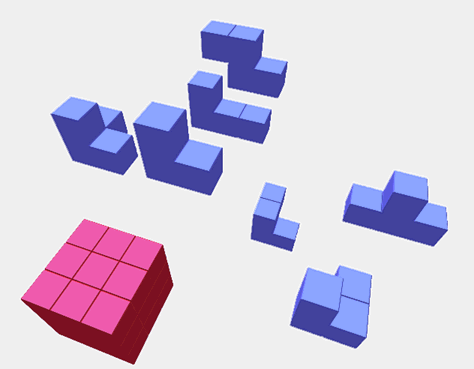
pfdLoadFile() uses the function pfdLoadFile_dwb() to load Designer's Workbench files into IRIS Performer run-time data structures.
The DXF format originated with Autodesk's AutoCAD database modeling system. The version recognized by the pfdLoadFile_dxf() database importer is a subset of ASCII Drawing Interchange Format (DXF) Release 12. The binary version of the DXF format, also known as DXF, isn't supported. Source code for the importer is in the file /usr/share/Performer/src/lib/libpfdb/libpfdxf/pfdxf.c. pfdLoadFile_dxf() was derived from the DXF-to-DKB data file converter developed and placed in the public domain by Aaron A. Collins.
The image in Figure 9-3 shows a DXF model of the famous Utah teapot. This model was loaded from DXF format using the pfdLoadFile_dxf() database importer.

The DXF format has an unusual though well-documented structure. The general organization of a DXF file is
HEADER section with general information about the file
TABLES section to provide definitions for named items, including:
LTYPE, the line-type table
LAYER, the layer table
STYLE, the text-style table
VIEW, the view table
UCS, the user coordinate-system table
VPORT, the viewport configuration table
DIMSTYLE, the dimension style table
APPID, the application identification table
BLOCKS section containing block definition entities
ENTITIES section containing entities and block references
END-OF-FILE
Within each section are groups of values, where each value is defined by a two-line pair of tokens. The first token is a numeric code indicating how to interpret the information on the next line. For example, the sequence
10 1.000 20 5.000 30 3.000 |
defines a “start point” at the XYZ location (1, 5, 3). The codes 10, 20, and 30 indicate, respectively, that the primary X, Y, and Z values follow. All data values are retained in a set of numbered registers (10, 20, and 30 in this example), which allows values to be reused. This simple state-machine type of run-length coding makes DXF files space-efficient at the cost of making them harder to interpret.
pfdLoadFile() uses the function pfdLoadFile_dxf() to load DXF format files into IRIS Performer run-time data structures.
Several widely available technical books provide full details of this format if you need more information. Chief among these are AutoCAD Programming, 2nd Edition, by Dennis N. Jump, Windcrest Books, 1991, and AutoCAD: The Complete Reference, Second Edition, by Nelson Johnson, Osborne McGraw-Hill, 1991.
The OpenFlight format is a binary format used for input and output by the MultiGen and ModelGen database modeling tools produced by MultiGen. It is a comprehensive format that can represent nearly all of IRIS Performer's advanced concepts, including object hierarchy, instancing, level-of-detail selection, light-point specification, texture mapping, and material property specification.
MultiGen has provided an OpenFlight-format importer, pfdLoadFile_flt(), for your use. The loaders and associated documentation are in the directories /usr/share/Performer/src/lib/libpfdb/libpfflt11 and libpfflt14. Refer to the Readme files in these directories for important information about the loaders and for help in contacting MultiGen for information about pfdLoadFile_flt() or the OpenFlight format.
The image in Figure 9-4 shows a model of a spacecraft created by Viewpoint Animation Engineering using MultiGen. This OpenFlight format model was loaded into IRIS Performer using pfdLoadFile_flt().
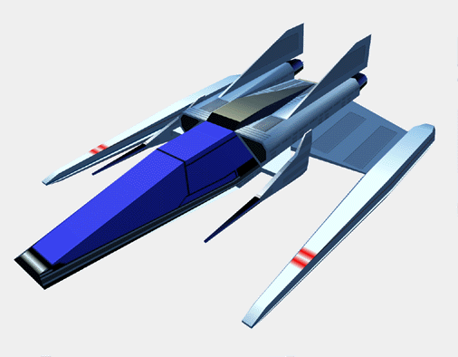
pfdLoadFile() uses the function pfdLoadFile_flt() to load OpenFlight format files into IRIS Performer run-time data structures.
Files in the OpenFlight format are structured as a linear sequence of records. The first few bytes of each record are a header containing an op-code, the length of the record, and possibly an ASCII name for the record. The first record in the file is a special “database header” record whose op-code, stored as a 2-byte short integer, has the value 1. This opcode header can be used to identify OpenFlight-format files. By convention, these files have a “.flt” filename extension.
pfdLoadFile_flt() makes use of several environment variables when locating data and texture files. These variables and several additional functions, including pfdConverterMode_flt(), pfdGetConverterMode_flt(), and pfdConverterAttr_flt() assist in OpenFlight file processing.
The “.gds” format (also known as the “Things” format) is used in at least one CAD system, and a minimal loader for this format has been developed for IRIS Performer users. The IRIS Performer loader for “.gds” files is located in the /usr/share/Performer/src/lib/libpfdb/libpfgds directory.
The GDS format subset accepted by the pfdLoadFile_gds() function is easy to describe. It consists of the following five sequential sections in an ASCII file.
The number of vertices, which is given following a “YIN” tag.
The vertices, with one X, Y, Z triple per line for vertices lines.
The number zero on a line by itself.
The number of polygons on a line by itself.
A series of polygon definitions, each of which is represented on two or more lines. The first line contains the number one and the name of a material to use for the polygon. The next line or lines contain the indices for the polygons vertices. The first number on the first line is the number of vertices. This is followed by that number of vertex indices on that, and possibly subsequent, lines.
pfdLoadFile() uses the function pfdLoadFile_gds() to load “.gds” format files into IRIS Performer.
The GFO format is the simple ASCII format of the barcelona database that is provided in the IRIS Performer sample database directory. This database represents the famous German Pavilion at the Barcelona Exhibition of 1929, which was designed by Ludwig Mies van der Rohe and is shown in Figure 9-5.
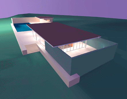
The source code for the GFO-format loader is provided in the file /usr/share/Performer/src/lib/libpfdb/libpfgfo/pfbin.c.
pfdLoadFile() uses the function pfdLoadFile_gfo() to load GFO format files into IRIS Performer run-time data-structures.
When working with GFO files, remember that hardware lighting isn't used since all illumination effects have already been accounted for with the ambient color at each vertex.
The GFO format defines polygons with a color at every vertex. It is the output format of an early radiosity system. Files in this format have a simple ASCII structure, as indicated by the following abbreviated GFO file:
scope {
v3f {42.9632 8.7500 0.9374}
cpack {0x8785a9}
v3f {42.9632 8.0000 0.9374}
cpack {0x8785a9}
...
v3f {-1.0000 -6.5858 10.0000}
cpack {0xffffff}
polygon {cpack[0] v3f[0] cpack[1] v3f[1] cpack[2] v3f[2] cpack[3] v3f[3] }
polygon {cpack[4] v3f[4] cpack[5] v3f[5] cpack[6] v3f[6] cpack[7] v3f[7] }
...
polygon {cpack[7330] v3f[7330] cpack[7331] v3f[7331] cpack[7332] v3f[7332] cpack[7333] v3f[7333] }
instance {
polygon[0]
polygon[1]
...
polygon[2675]
}
}
|
This example is taken from the file barcelona-l.gfo, one of only two known databases in the GFO format. The importer uses functions from the libpfdu library (such as those from the pfdBuilder) to generate efficient shared triangle strips. This increases the speed with which GFO databases can be drawn and reduces the size and complexity of the loader, since the builder's functions hide the details of the pfGeoSet construction process.
The “.im” format is a simple format developed for test purposes by the IRIS Performer engineering team. As new features are added to IRIS Performer, the “.im” loader is extended to allow experimentation and testing. A recent example of this is support for pfText, pfString, and pfFont objects which can be seen by running perfly on the sample data file fontsample.im. The IRIS Performer “.im” loader is in the /usr/share/Performer/src/lib/libpfdb/libpfim directory.
Here is an example IM format file that creates an extruded 3D text string. Copy this to a file ending in the extension “.im” and load it into Perfly. For a complete example of how text is handled in IRIS Performer, use Perfly to examine the file /usr/share/Performer/data/fontsample2.im.
breakup 0 0.0 0 0 new root top end_root new font mistr-extruded Mistr 3 end_font new str_text textnode mistr-extruded 1 Hello World|| end_text attach top textnode |
pfdLoadFile() uses the function pfdLoadFile_im() to load “.im” format files into IRIS Performer run-time data structures:
pfdLoadFile_im() searches the current IRIS Performer file path for the named file and returns a pointer to the pfNode parenting the imported scene graph, or NULL if the file isn't readable or doesn't contain a valid database.
The AAI/Graphicon “.irtp” format is used by the TopGen database modeling system and by the Graphicon-2000 image generator. The name IRTP is an acronym for Interactive Real-Time PHIGS. The IRIS Performer “.irtp” loader is in the /usr/share/Performer/src/lib/libpfdb/libpfirtp directory. Though loader does not support the more arcane IRTP features, such as binary separating planes or a global matrix table, it has served as a basis for porting applications to IRIS Performer and the RealityEngine.
pfdLoadFile() uses the function pfdLoadFile_irtp() to load IRTP format files into IRIS Performer run-time data-structures.
The Open Inventor object-oriented 3D-graphics toolkit defines a persistent data format that is also a superset of the VRML networked graphics data format. The image in Figure 9-6 shows a sample Open Inventor data file.

The model in Figure 9-6 represents one design for the perennial “personal aircar of the future” concept. It was created, using Imagine, by Mike Halvorson of Impulse, and was modeled after the Moller 400 as described in Popular Mechanics.
The Open Inventor data-file loader provided with IRIS Performer reads both binary and ASCII format Open Inventor data files. Open Inventor scene graph description files in both formats have the suffix “.iv” appended to their file names.
Here is a simple Open Inventor file that defines a cone:
#Inventor V2.1 ascii

Separator {
 Cone {
 }
}
|
The source code for the Open Inventor format importer is provided in the libpfdb/libpfiv source directory.
pfdLoadFile() uses the function pfdLoadFile_iv() to load Open Inventor format files into IRIS Performer run-time data-structures. Because VRML is a subset of Open Inventor 2.1, if you have Open Inventor 2.1 installed, you can also read VRML “.wrl” files using pfdLoadFile(). IRIS Performer also comes with an Inventor loader that works with Open Inventor 2.0, if Open Inventor 2.1 is not installed.
The Lightscape Visualization system is a product of Lightscape Technologies, Inc., and is designed to compute accurate simulations of global illumination within complex 3D environments. The output files created with Lightscape Visualization can be read into IRIS Performer for real-time visual exploration.
Lightscape Technologies provides importers for two of their database formats, the simple ASCII LSA format and the comprehensive binary LSB format. These loaders are in the /usr/share/Performer/src/lib/libpfdb/libpflsa and libpflsb directories, in the files pflsa.c and pflsb.c.Files in the LSA format are in ASCII and have the following components:
a 4x4 view matrix representing a default transformation
counts of the number of independent triangles, independent quadrilaterals, triangle meshes, and quadrilateral meshes in the file
geometric data definitions
There are four types of geometric definitions in LSA files. The formats of these definitions are as shown in Table 9-7.
Table 9-7. Geometric Definitions in LSA Files
Geometric Type | Format |
|---|---|
Triangle | t X1 Y1 Z1 C1 X2 Y2 Z2 C2 X3 Y3 Z3 C3 |
Triangle mesh | tm n X1 Y1 Z1 C1 X2 Y2 Z2 C2 ... |
Quadrilateral | q X1 Y1 Z1 C1 X2 Y2 Z2 C2 X3 Y3 Z3 C3 X4 Y4 Z4 C4 |
Quadrilateral mesh | qm n X1 Y1 Z1 C1 X2 Y2 Z2 C2 ... |
The Cn values in Table 9-7 refer to colors in the format accepted by the IRIS GL function cpack(); these colors should be provided in decimal form. The X, Y, and Z values are vertex coordinates. Polygon vertex ordering in LSA files is consistently counter-clockwise, and polygon normals are not specified. The first few lines of the LSA sample file chamber.0.lsa provide an example of the format:
0.486911 0.03228900 0.979046 0.9596590 -1.665110 0.00944197 0.286293 0.2806240 0.000000 1.92730000 -0.017805 -0.0174524 0.240398 -5.54670000 13.021200 13.4945000 1782 4751 0 0 t 4.35 -7.3677 2.57 6188666 6.5 -9.3 2.57 5663353 4.35 -9.3 2.57 5728890 t 6.5 -9.3 2.57 5663353 4.35 -7.3677 2.57 6188666 6.5 -8.2463 2.57 6057596 |
The count line indicates that the file contains 1782 independent triangles and 4751 independent quadrilaterals, which together represent 11,284 triangles. The image in Figure 9-7 shows this database, the New Jerusalem City Hall. This was produced by A. J. Diamond of Donald Schmitt and Company, Toronto, Canada, using the Lightscape Visualization system.

pfdLoadFile() uses the function pfdLoadFile_lsa() to load LSA format files into IRIS Performer run-time data-structures.
Files in the LSB binary format have a very different structure from LSA files. Representing not just polygon data, they contain much of the structural information present in the “.ls” files used by the Lightscape Visualization system, including material, layer, and texture definitions as well as a hierarchical mesh definition for geometry. This information is structured as a series of data sections, which include:
the signature, a text string that identifies the file
the header, which contains global file information
the material table, defining material properties
the layer table, defining grouping and association
the texture table, referencing texture images
geometry in the form of clusters
The format of the geometric clusters is somewhat complicated. A cluster is a group of coplanar surfaces called patches that share a common material, layer, and normal. Each patch shares at least one edge with another patch in the cluster. Each patch defines either a convex quadrilateral or a triangle, and patches represent quad-trees called nodes. Each node points to its corner vertices and its children. The leaf nodes point to their corner vertices and the child pointers can optionally point to the vertices that split an edge of the node. Only the locations of vertices that are corners of the patches are stored in the file; other vertices are created by subdividing nodes of the quad-tree as the LSB file is loaded. The color information for each vertex is unique and is specified in the file.
The image in Figure 9-8 shows an LSB-format database developed during the design of a hospital operating room. This database was produced by the DeWolff Partnership of Rochester, New York, using the Lightscape Visualization system.
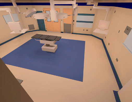
pfdLoadFile() uses the function pfdLoadFile_lsb() to load LSB format files into IRIS Performer run-time data-structures.
When working with Lightscape Technologies files, remember that hardware lighting isn't needed because all illumination effects have already been accounted for with the ambient color at each vertex.
The “.medit” format is used by the Medit database modeling system produced by Medit Productions. The Performer “.medit” loader is in the /usr/share/Performer/src/lib/libpfdb/libpfmedit directory.
pfdLoadFile() uses the function pfdLoadFile_medit() to load MEDIT format files into IRIS Performer run-time data-structures.
The “.nff” format was developed by Eric Haines as a way to provide standard procedural databases for evaluating ray tracing software. IRIS Performer includes an extended NFF loader with superquadric torus support, a named build keyword, and numerous small bug fixes. The “.nff” loader is located in the /usr/share/Performer/src/lib/libpfdb/libpfnff directory.
The file /usr/share/Performer/data/sampler.nff uses each of the NFF data types. It is an excellent way to explore the “Show Tree”, “Draw Style”, and “Highlight Mode” features of Perfly. It is included here:
#-- torus f .75 .00 .25 .6 .8 20 0 t 5 5 0 0 0 1 2 1 build torus #-- cylinder f .00 .75 .25 .6 .8 20 0 c 15 5 -3 2 15 5 3 2 #-- put a disc on the top and bottom of the cylinder d 15 5 -3 0 0 -1 0 2 d 15 5 3 0 0 1 0 2 build cylinder #-- cone f .00 .25 .75 .6 .8 20 0 c 25 5 -3 3 25 5 3 0 #-- put a disc on the bottom of the cone d 25 5 -3 0 0 -1 0 3 build cone #-- sphere f .75 .00 .75 .6 .8 20 0 s 5 15 0 3 build sphere #-- hexahedron f .25 .25 .50 .6 .8 20 0 h 13 13 -2 17 17 2 build hexahedron #-- superquadric sphere f .80 .10 .30 .6 .8 20 0 ss 25 15 0 2 2 2 .1 .4 build superquadric_sphere #-- disc (washer shape) f .20 .20 .90 .6 .8 20 0 d 5 25 0 0 0 1 1 2.5 build disc #-- grid (height field) f .80 .80 .10 .6 .8 20 0 g 4 4 12 18 22 28 0 4 0 0 0 0 0 1 0 0 0 0 -1 0 0 0 0 0 build grid #-- superquadric torid f .40 .20 .60 .6 .8 20 0 st 25 25 0 0.5 0.5 0.5 .33 .33 3 build superquadric_torid #-- polygon with no normals f .20 .20 .20 .6 .8 20 0 p 4 -5 -5 -10 35 -5 -10 35 35 -10 -5 35 -10 build polygon |
pfdLoadFile() uses the function pfdLoadFile_nff() to load NFF format files into IRIS Performer run-time data-structures.
The OBJ format is an ASCII data representation read and written by the Wavefront Technology Model program. A number of database models in this format have been placed in the public domain, making this a useful format to have available. IRIS Performer provides the function pfdLoadFile_obj() to import OBJ files. The source code for pfdLoadFile_obj() is in the file pfobj.c in the /usr/share/Performer/src/lib/libpfdb/libpfobj loader source directory.
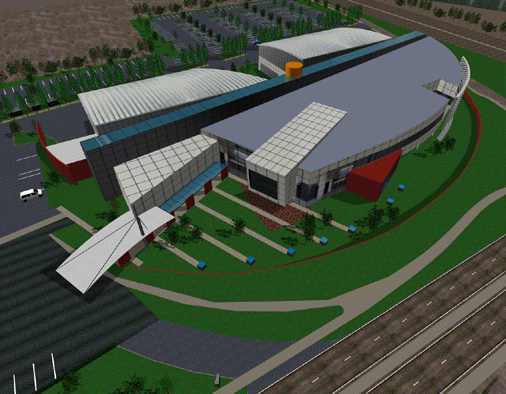
The OBJ-format database shown in Figure 9-9 models an office building that's part of the Silicon Graphics corporate campus in Mountain View, California.
Files in the OBJ format have a flexible all-ASCII structure, with simple keywords to direct the parsing of the data. This format is best illustrated with a short example that defines a texture-mapped square:
#-- `v' defines a vertex; here are four vertices v -5.000000 5.000000 0.000000 v -5.000000 -5.000000 0.000000 v 5.000000 -5.000000 0.000000 v 5.000000 5.000000 0.000000 #-- `vt' defines a vertex texture coordinate; four are given vt 0.000000 1.000000 0.000000 vt 0.000000 0.000000 0.000000 vt 1.000000 0.000000 0.000000 vt 1.000000 1.000000 0.000000 #-- `usemtl' means select the material definition defined #-- by the name MaterialName usemtl MaterialName #-- `usemap' means select the texturing definition defined #-- by the name TextureName usemap TextureName #-- `f' defines a face. This face has four vertices ordered #-- counter-clockwise from the upper left in both geometric #-- and texture coordinates. Each pair of numbers separated #-- by a slash indicates vertex and texture indices, #-- respectively, for a polygon vertex. f 1/1 2/2 3/3 4/4 |
pfdLoadFile() uses the function pfdLoadFile_obj() to load Wavefront OBJ files into IRIS Performer run-time data-structures.
The PHD format was created to describe the geometric polyhedron definitions derived mathematically by Andrew Hume and by the Kaleido program of Zvi Har'El. This format describes only the geometric shape of polyhedra; it provides no specification for color, texture, or appearance attributes such as specularity.
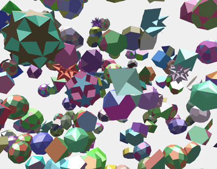
The IRIS Performer sample data directories contain numerous polyhedra in the PHD format. The image in Figure 9-10 shows many of the polyhedron definitions laboriously computed by Andrew Hume.
The source code for the PHD-format importer is in the file /usr/share/Performer/src/lib/libpfdb/libpfpoly/pfphd.c.
PHD format files have a line-structured ASCII form; an initial keyword defines the contents of each line of data. The file format consists of a filename definition (introduced by the keyword file) followed by one or more object definitions.
Object definitions are bracketed by the keywords object.begin and object.end and contain one or more polygon definitions. Objects can have a name in quotes following the object.begin keyword; such a name is used by the loader for the name of the corresponding IRIS Performer node.
Polygon definitions are bracketed by the keywords polygon.begin and polygon.end and contain three or more vertex definitions.
Vertex definitions are introduced by the vertex keyword and define the X, Y, and Z coordinates of a single vertex.
The following is a PHD-format definition of a unit-radius tetrahedron centered at the origin of the coordinate axes. It is derived from the database developed by Andrew Hume but has since been translated, scaled, and reformatted.
file 000.phd object.begin "tetrahedron" polygon.begin vertex -0.090722 -0.366647 0.925925 vertex 0.544331 -0.628540 -0.555555 vertex 0.453608 0.890430 0.037037 polygon.end polygon.begin vertex -0.907218 0.104757 -0.407407 vertex -0.090722 -0.366647 0.925925 vertex 0.453608 0.890430 0.037037 polygon.end polygon.begin vertex -0.090722 -0.366647 0.925925 vertex -0.907218 0.104757 -0.407407 vertex 0.544331 -0.628540 -0.555555 polygon.end polygon.begin vertex 0.453608 0.890430 0.037037 vertex 0.544331 -0.628540 -0.555555 vertex -0.907218 0.104757 -0.407407 polygon.end object.end |
pfdLoadFile() uses the function pfdLoadFile_phd() to load PHD format files into IRIS Performer run-time data-structures.
The pfdLoadFile_phd() function composes a color with red, green, and blue components uniformly distributed within the range 0.2 to 0.7 that is consistent for each polygon with the same number of vertices within a single polyhedron.
The PTU format is named for the IRIS Performer Terrain Utilities, of which the pfdLoadFile_ptu() function is the sole example at the present time. This function accepts as input the name of a control file (the file with the “.ptu” filename extension) that defines the desired terrain parameters and references additional data files.
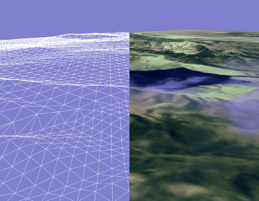
The database shown in Figure 9-11 represents a portion of the Yellowstone National Park. This terrain database was generated completely by the IRIS Performer Terrain Utility data generator from digital terrain elevation data and satellite photographic images. Image manipulation is performed using the Silicon Graphics ImageVision Library™ functions.
The PTU control file has a fixed format that doesn't use keywords. The contents of this file are simply ASCII values representing the following data items:
The name to be assigned to the top-level pfNode built by pfdLoadFile_ptu().
The number of desired levels-of-detail (LOD) for the resulting terrain surface. The pfdLoadFile_ptu() function will construct this many versions of the terrain, each representing the whole surface but with exponentially fewer numbers of polygons in each version.
The numbers of highest-LOD tiles that will tessellate the entire terrain surface in the X and Y axis directions.
Two numeric values that define the mapping of texture image pixels to world-coordinate terrain geometry. These values are the number of meters per texel (texture pixel) of filtered grid post data in the X and Y axis dimensions.
The name of an image file that represents terrain height at regularly spaced sample points in the form of a monochrome image whose brightness at each pixel indicates the height at that sample point. Additional arguments are the number of samples in the input image in the X and Y directions, as well as the desired number of samples in these directions. The pfdLoadFile_ptu() function resamples the grid posts from the original to the desired resolution by filtering the height image using SGI ImageVision Library functions.
The name of an image file that represents the terrain texture image at regularly spaced sample points. Subsequent arguments are the number of samples in the image in the X and Y directions as well as the desired number of samples in these directions. This image will be applied to the terrain geometry. The scale values provided in the PTU file allow the terrain grid and texture image to be adjusted to create an orthographic alignment.
An optional second texture-image filename that serves as a detail texture when the terrain is viewed on RealityEngine systems. This texture is used in addition to the base texture image.
An optional detail-texture spline-table definition. The blending of the primary texture image and the secondary detail texture is controlled by a blend table defined by this spline function. The spline table is optional even when a detail texture is specified. Detail texture and its associated blend functions are applicable only on RealityEngine systems.
The source code for the PTU-format importer is provided in the file /usr/share/Performer/src/lib/libpfdb/libpfptu/pfptu.c.
pfdLoadFile() uses the function pfdLoadFile_ptu() to load PTU format files into IRIS Performer run-time data-structures.
The S1000 format is used by the United States ARMY SIMNET distributed simulation system for armored vehicle training. The IRIS Performer “.s1k” loader is in the /usr/share/Performer/src/lib/libpfdb/libpfs1k directory. It consists of two libraries, an IRIS Performer loader library developed by Todd R. Pravata of Texas Instruments, Inc., in Plano Texas and an S1000 data format toolkit that may be requested from the following source:
Frank Abbruscato
Director of Data Support Division
Digital Processing Center
US Army Topographic Engineering Center
7701 Telegraph Road
Alexandria, VA 22310-3864
phone: 703-355-2954
email: [email protected]
The Texas Instruments S1K Loader is built on top of the S1000 Data Base API developed by Loral Advanced Distributed Simulation. The S1000 API is used to access the following S1000 data base elements:
3-D polygons for terrain, micro-terrain and culture.
Model instance data
Model geometry
Texture patterns
General data base information
The following S1000 database structures are not accessed by the loader since they are two-dimensional representations of the database terrain and features:
Pole sets
Defragmented Terrain Areal Features
The S1K Loader does not currently support loading dynamic models (with articulated parts), though support is planned in future releases.
The S1000 data base loader uses the concept of a “control file” to control the database load. An S1K control file is an ascii file that substitutes for the formatted database file common to other loaders. The control file must have a “.s1k” file suffix to be recognized as an S1K control file. Keyword and parameter value pairs specified by the user are placed in the control file to tailor the database load to the user's requirements. Examples of control file parameters are:
S1KPROJ <project_directory> PROJECT <project_name> ASSEMBLY_PREFIX <assembly_prefix> SEARCH_WINDOW <xmin> <ymin> <xmax> <ymax> ORIGIN <x> <y> UTM VIEWING_MODE [ OTW | THERMAL | BOTH ] INCLUDE_INACTIVE_POLYGONS MODEL_FILTER <filter_regexp> VTX_NORMALS LEAF_SIZE_MAX <integer_size> |
The minimum control file specifies which project to load. The default is to load the entire project. The assembly prefix is assumed to be the same as the project name unless the user has specified a different assembly prefix. The control file also allows the user to specify the S1K project directory. If the project directory is specified in the control file then this setting overrides the environment variable setting S1KPROJ if any. The user may load a portion of the entire S1000 data base by specifying the coordinates of a search window (see the S1000 API User's Manual for details about search window selection).
The database load occurs in either assembly (ASSY) coordinates or UTM. The S1000 data base origin (the ASSY origin) is at the southwest corner of the assembly. If UTM coordinates are selected then the search window is assumed to be given in UTM coordinates and the output will be in UTM coordinates. The user may however establish his own local reference frame by specifying an origin for the output database. Again, if UTM is specified, the origin is assumed to be given in UTM, otherwise ASSY. The S1000 API provides the capability to convert from UTM to assembly coordinates. The assembly coordinate frame is a topocentric rectangular grid located at the southwest corner of the assembly area.
The “.sgf” format is used at the United States Naval Academy as a standard graphics format for geometric data. The loader was developed based on the description of the standard graphics format as described by David F. Rogers and J. Alan Adams in the book Mathematical Elements for Computer Graphics. The IRIS Performer “.sgf” format loader is located in the directory /usr/share/Performer/src/lib/libpfdb/libpfsgf.
Here is the vector definition for four stacked squares in SGF form:
0, 0, 0 1, 0, 0 1, 1, 0 0, 1, 0 0, 0, 0 1.0e37, 1.0e37, 1.0e37 0, 0, 1 1, 0, 1 1, 1, 1 0, 1, 1 0, 0, 1 1.0e37, 1.0e37, 1.0e37 0, 0, 2 1, 0, 2 1, 1, 2 0, 1, 2 0, 0, 2 1.0e37, 1.0e37, 1.0e37 0, 0, 3 1, 0, 3 1, 1, 3 0, 1, 3 0, 0, 3 1.0e37, 1.0e37, 1.0e37 |
pfdLoadFile() uses the function pfdLoadFile_sgf() to load SGF format files into IRIS Performer run-time data-structures.
The Silicon Graphics Object format is used by several cool utility programs and was one of the first database formats supported by IRIS Performer. The image in Figure 9-12 shows a model generated by Paul Haeberli and loaded into perfly by the pfdLoadFile_sgo() database importer.

Objects in the SGO format have per-vertex color specification and multiple data formats. Objects contained in SGO files are constructed from three data types:
lists of quadrilaterals
lists of triangles
triangle meshes
Objects of different types can be included as data within one SGO file.
The SGO format has the following structure:
A magic number, 0x5424, which identifies the file as an SGO file.
A set of data for each object. Each object definition begins with an identifying token, followed by geometric data. There can be multiple object definitions in a single file. An end-of-data token terminates the file.
The layout of an SGO file is
<SGO-file magic number> <data-type token for object #1> <data for object #1> <data-type token for object #2> <data for object #2> ... <data-type token for object #n> <data for object #n> <end-of-data token> |
Each of the identifying tokens is 4 bytes long. Table 9-8 lists the symbol, value, and meaning for each token.
Table 9-8. Object Tokens in the SGO Format
Symbol | Value | Meaning |
|---|---|---|
OBJ_QUADLIST | 1 | Independent quadrilaterals |
OBJ_TRILIST | 2 | Independent triangles |
OBJ_TRIMESH | 3 | Triangle mesh |
OBJ_END | 4 | End-of-data token |
The next word following any of the three object types is the number of 4-byte words of data for that object. The format of this data varies depending on the object type.
For quadrilateral list (OBJ_QUADLIST) and triangle list (OBJ_TRILIST) objects, there are nine words of floating-point data for each vertex, as follows:
Three words that specify the components of the normal vector at the vertex.
Three words that specify the red, green, and blue color components, scaled to the range 0.0 to 1.0.
Three words that specify the X, Y, and Z coordinates of the vertex itself.
In quadrilateral lists, vertices are in groups of four, so there are 4 X 9 = 36 words of data for each quadrilateral. In triangle lists, vertices are in groups of three, for 3 X 9 = 27 words per triangle.
The triangle mesh, OBJ_TRIMESH, is the most complicated of the three object data types. Triangle mesh data consists of a set of vertices followed by a set of mesh-control commands. Triangle mesh data has the following format:
A long word that contains the number of words in the complete triangle mesh data packet.
A long word that contains the number of floating-point words required by the vertex data, at nine words per vertex.
The data for each vertex, consisting of nine floating-point words representing normal, color, and coordinate data.
A list of triangle mesh controls.
The triangle mesh controls, each of which is one word in length, are listed in Table 9-9.
Table 9-9. Mesh Control Tokens in the SGO Format
Symbol | Value | Meaning |
|---|---|---|
OP_BGNTMESH | 1 | Begin a triangle strip. |
OP_SWAPTMESH | 2 | Exchange old vertices. |
OP_ENDBGNTMESH | 3 | End, then begin a strip. |
OP_ENDTMESH | 4 | Terminate triangle mesh. |
The triangle-mesh controls are interpreted sequentially. The first control must always be OP_BGNTMESH, which initiates the mesh-decoding logic. After each mesh control is a word (of type long integer) that indicates how many vertex indices follow. The vertex indices are in byte offsets, so to access vertex n, you must use the byte offset n X 9 X 4. See the graphics library reference books listed under “Bibliography” for more information on triangle meshes (particularly see the IRIS GL books, if you're using IRIS GL, for information on the swap-triangle-mesh concept).
pfdLoadFile() uses the function pfdLoadFile_sgo() to load SGO format files into IRIS Performer run-time data-structures.
You can find the source code for the SGO-format importer in the file pfsgo.c. This importer doesn't attempt to decode any triangle meshes present in input files; instead, it terminates the file conversion process as soon as an OBJ_TRIMESH data-type token is encountered. If you use SGO-format files containing triangle meshes you'll need to extend the conversion support to include the triangle mesh data type.
The “.spf” format is used at the United States Naval Academy as a simple polygon file format for geometric data. The loader was developed based on the description in the book Mathematical Elements for Computer Graphics. The IRIS Performer “.spf” loader is in the /usr/share/Performer/src/lib/libpfdb/libpfspf directory.
The following “.spf” format file is defined in that book.
polygon with a hole 14,2 4,4 4,26 20,26 28,18 28,4 21,4 21,8 10,8 10,4 10,12 10,20 17,20 21,16 21,12 9,1,2,3,4,5,6,7,8,9 5,10,11,12,13,14 |
If you look at this file in Perfly you will see that the hole is not cut out of the letter “A” as might be desired. Such computational geometry computations are not considered the province of simple database loaders.
pfdLoadFile() uses the function pfdLoadFile_spf() to load SPF format files into IRIS Performer run-time data-structures.
The Sierpinski Sponge (a.k.a. Menger Sponge) loader is not based on a data format but rather is a procedural data generator. The loader interprets the portion of the user provided “file name” before the period and extension as an integer which specifies the number of recursive subdivisions desired in data generation. For example, providing the pseudo filename “3.sponge” to perfly will result in the Sponge loader being invoked and generating a sponge object using three levels of recursion, resulting in a 35712 polygon database object. The IRIS Performer “.sponge” loader can be found in the /usr/share/Performer/src/lib/libpfdb/libpfsponge directory.
pfdLoadFile() uses the function pfdLoadFile_sponge() to load Sponge format files into IRIS Performer run-time data-structures.
The “.star” format is a distillation of astronomical data from the Yale Compact Star Chart. The sample data file /usr/share/Performer/data/3010.star contains data from the YCSC that has been reduced to a list of the 3010 brightest stars as seen from Earth and positioned as 3010 points of light on a unit-radius sphere. The IRIS Performer “.star” loader can read this data and is provided as a convenience for making dusk, dawn, and night-time scenes. The loader is in the /usr/share/Performer/src/lib/libpfdb/libpfstar directory.
Data in a “.star” file is simply a series of ASCII lines with the “s” (for star) keyword followed by X, Y, and Z coordinates, brightness, and an optional name. Here are the 10 brightest stars (excluding Sol) in the “.star” format:
s -0.18746032 0.93921369 -0.28763914 1.00 Sirius s -0.06323564 0.60291260 -0.79529721 1.00 Canopus s -0.78377002 -0.52700269 0.32859191 1.00 Arcturus s 0.18718566 0.73014212 0.65715599 1.00 Capella s 0.12507832 -0.76942003 0.62637711 0.99 Vega s 0.13051330 0.68228769 0.71933979 0.99 Capella s 0.19507207 0.97036278 -0.14262892 0.98 Rigel s -0.37387931 -0.31261155 -0.87320572 0.94 Rigil Kentaurus s -0.41809806 0.90381104 0.09121194 0.94 Procyon s 0.49255905 0.22369388 -0.84103900 0.92 Achernar |
pfdLoadFile() uses the function pfdLoadFile_star() to load Star format files into IRIS Performer run-time data-structures.
The STL format is used to define 3D solids to be imaged by 3D lithography systems. STL defines objects as collections of triangular facets, each with an associated face normal. The ASCII version of this format is known as STLA and has a very simple structure.
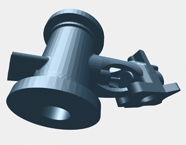
The image in Figure 9-13 shows a typical STLA mechanical CAD database. This model is defined in the bendix.stla sample data file.
The source code for the STLA-format loader is in the files /usr/share/Performer/src/lib/libpfdb/libpfstla/pfstla.c.
STLA-format files have a line-structured ASCII form; an initial keyword defines the contents of each line of data. An STLA file consists of one or more facet definitions, each of which contains
the facet normal, indicated with the facet normal keyword
the facet vertices, bracketed by outer loop and endloop keywords
the endloop keyword
Here is an excerpt from nut.stla, one of the STLA files provided in the IRIS Performer sample data directories. These are the first two polygons of a 524-triangle hex-nut object:
facet normal 0 -1 0 outer loop vertex 0.180666 -7.62 2.70757 vertex -4.78652 -7.62 1.76185 vertex -4.436 -7.62 0 endloop endfacet facet normal -0.381579 -0.921214 -0.075915 outer loop vertex -4.48833 -7.59833 0 vertex -4.436 -7.62 0 vertex -4.78652 -7.62 1.76185 endloop endfacet |
Use this function to import data from STLA-format files into IRIS Performer run-time data structures:
pfNode *pfdLoadFile_stla(char *fileName); |
pfdLoadFile_stla() searches the current IRIS Performer file path for the file named by the fileName argument and returns a pointer to the pfNode that parents the imported scene graph, or NULL if the file isn't readable or doesn't contain recognizable STLA format data.
The SuperViewer (SV) format is one of the several database formats that the I3DM database modeling tool can read and write. The I3DM modeler was developed by John Kichury of Silicon Graphics and is provided with IRIS Performer. The source code for the SV format importer is in the file pfsv.c.
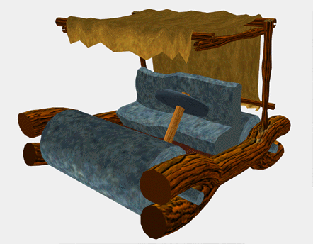
The passenger vehicle database shown in Figure 9-14 was modeled using I3DM and is stored in the SV database format.
Within SV files, object geometry and attributes are described between text lines that contain the keywords model and endmodel. For example:
model wing geometry and attributes endmodel |
Any number of models can appear within a SuperViewer file. The geometry and attribute data mentioned above each consist of one of the following types:
3D Polygon with vertex normals and optional texture coordinates
poly3dn <num_vertices> [textured]
x1 y1 z1 nx1 ny1 nz1  [s1 t1]
x2 y2 z2 nx2 ny2 nz2  [s2 t2]
...
Where
Xn Yn Zn are the nth vertex coordinates
Nxn Nyn Nzn are the nth vertex normals
Sn Tn are the nth texture coordinates
3D Triangle mesh with vertex normals and optional texture coordinates
tmeshn <num_vertices> [textured]
x1 y1 z1 nx1 ny1 nz1  [s1 t1]
x2 y2 z2 nx2 ny2 nz2  [s2 t2]
...
Where
Xn Yn Zn are the nth vertex coordinates
Nxn Nyn Nzn are the nth vertex normals
Sn Tn are the nth texture coordinates
Material definition. If the material directive exists before a model definition, it is taken as a new material specification. Its format is:
material n Ar Ag Ab Dr Dg Db Sr Sg Sb Shine Er Eg Eb
Where
n is an integer specifying a material number
Ar Ag Ab is the ambient color
Dr Dg Db is the diffuse color
Sr Sg Sb is the specular color
Shine is the material shininess
Er Eg Eb is the emissive color
If the material directive exists within a model description, the format is:
material n
Where n is an integer specifying which material (as defined by the material description above) is to be assigned to subsequent data.
Texture definition. If the texture directive exists before a model definition it is taken as a new texture specification. Its format is:
texture n TextureFileName
If the texture directive exists within a model description, the format is:
texture n
Where n is an integer specifying which texture (as defined by the texture description above) is to be assigned to subsequent data.
Backface polygon display mode. The backface directive is specified within model definitions to control backface polygon culling:
backface mode
Where a mode of “on” allows the display of backfacing polygons and a mode of “off” suppresses their display.
In actual use the SV format is somewhat self-documenting. Here is part of the SV file apple.sv from the /usr/share/Performer/data directory:
material 20 0.0 0.0 0 0.400000 0.000000 0 0.333333 0.000000 0.0 10.0000 0 0 0 material 42 0.2 0.2 0 0.666667 0.666667 0 0.800000 0.800000 0.8 94.1606 0 0 0 material 44 0.0 0.2 0 0.000000 0.200000 0 0.000000 0.266667 0.0 5.0000 0 0 0 texture 4 prchmnt.rgb texture 6 wood.rgb model LEAF material 44 texture 4 backface on poly3dn 4 textured 1.35265 1.35761 13.8338 0.0686595 -0.234553 -0.969676 0 1 0.88243 0.96366 14.0329 0.0502096 -0.376701 -0.924973 0 0.75 -4.44467 1.24026 13.5669 0.0363863 -0.337291 -0.940697 0.0909091 0.75 -2.37938 2.17479 13.3626 0.0363863 -0.337291 -0.940697 0.0909091 1 poly3dn 4 textured -2.37938 2.17479 13.3626 0.0363863 -0.337291 -0.940697 0.0909091 1 -4.44467 1.24026 13.5669 0.0363863 -0.337291 -0.940697 0.0909091 0.75 -9.23775 2.34664 13.1475 0.0344832 -0.284369 -0.958095 0.181818 0.75 -6.69592 3.94535 12.6716 0.0344832 -0.284369 -0.958095 0.181818 1 |
This excerpt specifies material properties and references texture images stored in the files prchmnt.rgb and wood.rgb, and then defines two polygons.
pfdLoadFile() uses the function pfdLoadFile_sv() to load SuperViewer files into IRIS Performer run-time data-structures.
The “.tri” format is used at the University of Minnesota's Geometry Center as a simple geometric data representation. The loader was developed by inspection of a few sample files. The IRIS Performer “.tri” loader is in the /usr/share/Performer/src/lib/libpfdb/libpftri directory.
These files have a very simple format: a line per vertex with position and normal given on each line as 6 ASCII numeric values. The file is simply a series of these triangle definitions. Here are the first two triangles from the data file /usr/share/Performer/data/mobrect.tri:
1.788180 1.000870 0.135214 0.076169 -0.085488 0.993423 1.574000 0.925908 0.146652 0.089015 -0.086072 0.992304 1.793360 0.634711 0.099409 0.076402 -0.111845 0.990784 0.836848 -0.595230 0.197960 0.156677 0.044503 0.986647 0.709638 -0.345676 0.210010 0.157642 0.021968 0.987252 0.581200 -0.535321 0.234807 0.145068 0.030985 0.988936 |
pfdLoadFile() uses the function pfdLoadFile_tri() to load “.tri” format files into IRIS Performer run-time data-structures.
The “.unc” format was once used at the University of North Carolina as a format for geometric data in an architectural walkthrough application. The loader was developed based on inspection of a few sample files. The IRIS Performer “.unc” loader is in the /usr/share/Performer/src/lib/libpfdb/libpfunc directory.
pfdLoadFile() uses the function pfdLoadFile_unc() to load UNC format files into IRIS Performer run-time data-structures.