An application based on IRIS Performer usually reads in a visual database from a file, then builds an internal data structure incorporating the information in that database. This data structure is called a scene graph; each element in the data structure is called a node. This chapter describes the types of nodes IRIS Performer uses to represent scenes internally. IRIS Performer provides many functions for creating, querying, modifying, and traversing scene graphs; such functions are also described here.
Note that this chapter focuses on the data types themselves rather than instances of those types. Chapter 6, “Database Traversal,” includes discussion of traversing sample scene graphs, in terms of actual objects rather than abstract data types. Objects in a scene graph (which is to say, instances of node types) have a hierarchical relationship based on the way the scene is laid out. The node types themselves, on the other hand, have an entirely different kind of hierarchical relationship based on the ways in which each node type is like other node types. (For instance, the pfBillboard node type is a subclass of the general pfNode node type.) This concept is discussed in more detail in the section of this chapter titled “Attribute Inheritance”.
A scene is represented by a graph of nodes. libpf provides several specialized node types that encapsulate many graphics and visual simulation features. These node types belong to a type hierarchy (which is distinct from the database hierarchy described in Chapter 6). The following sections describe the node types.
The basic element of a scene hierarchy is the node. While IRIS Performer supplies many specific types of nodes, it also uses a concept called class inheritance, which allows different node types to share attributes. For example, many types of nodes have children, but different node types perform different types of operations on their children. Only one set of routines is provided for adding and removing children, but all the node types can use these routines in the same manner to perform these common operations. This reduces the number of routines required and imposes a logical structure on the node types. This logical structure is also known as a class hierarchy, but it should not be confused with the scene hierarchy of nodes—the derivation hierarchy contains data types, not objects.
IRIS Performer's node hierarchy begins with the pfNode class, just as the overall class hierarchy begins with the pfObject type (see “Nodes”). All node types are subordinate to pfNode, and they inherit pfNode's attributes and the libpf routines for setting and getting attributes. In general, a node type inherits the attributes and routines of all its parent nodes in the type hierarchy.
Figure 5-1 shows the type hierarchy for the libpf node types.

Table 5-1 lists the basic node class and gives a simple description for each node type.
Table 5-1. IRIS Performer Node Types
Node Type | Node Class | Description |
|---|---|---|
Abstract | Basic node type | |
Branch | Groups zero or more children | |
Root | Parent of the visual database | |
Branch | Static Coordinate System | |
Branch | Dynamic Coordinate System | |
Branch | Selects among multiple children | |
Branch | Sequences through its children | |
Branch | Level-of-detail node | |
Branch | Renders coplanar geometry | |
Leaf | Contains light point specifications | |
Leaf | Contains specifications for a light source | |
Leaf | Contains geometric specifications | |
Leaf | Rotates geometry to face the eyepoint | |
Branch | Partitions geometry for efficient intersections | |
Branch | Morphs attribute data of its children | |
Leaf | Renders 2D and 3D text |
As discussed in “Attribute Inheritance”, all libpf nodes are arranged in a type hierarchy, which defines the inheritance of capabilities. The base node class is pfNode; all other nodes inherit the attributes of a pfNode. A pfNode is an abstract class, meaning that a pfNode can never be explicitly created by the application. Its purpose is to provide a root to the type hierarchy and to define the attributes that are common to all node types.
The following pfNode attributes are inherited by all other libpf node types:
Node name
Parent list
Bounding geometry
Intersection and traversal masks
Callback functions and data
User data
Bounding geometry, intersection masks, user data, and callbacks are advanced topics that are discussed in Chapter 6, “Database Traversal.”
The routines that set, get, and otherwise manipulate these attributes can be used by all libpf node types, as indicated by the keyword `Node' in the routine names. Nodes used as arguments to pfNode routines must be cast to pfNode* to match parameter prototypes, as shown in this example:
pfNodeName((pfNode*) dcs, "rotor_rotation"); |
However, you usually don't need to do this casting explicitly. When you use the C API and compile with the –ansi flag (which is the usual way to compile IRIS Performer applications), libpf provides macro wrappers around pfNode routines that automatically perform argument casting for you. When you use the C++ API, such type casting is not necessary.
In addition to sharing attributes, certain basic operations are provided for all node types. They include:
| New | Create and return a handle to a new node. | |
| Get | Get node attributes. | |
| Set | Set node attributes. | |
| Find | Find a node based on its name. | |
Print node data. | ||
| Copy | Copy node data. | |
| Delete | Delete a node. |
The Set operation is implied in the node attribute name. The names of the attribute-getting functions contain the string “Get”.
Example 5-1 illustrates the creation of a scene that includes two different kinds of pfNodes. (For information about pfScene nodes, see “pfScene Nodes”; for information about pfDCS nodes, see “pfDCS Nodes”.)
pfScene *scene;
pfDCS *dcs1, *dcs2;

scene = pfNewScene();         /* Create a new scene node */
dcs1 = pfNewDCS();            /* Create a new DCS node */
dcs2 = pfNewDCS();            /* Create a new DCS node */
pfCopy(dcs2, dcs1);           /* Copy all node attributes */
                              /*        from dcs1 to dcs2 */
pfNodeName(scene, "Scene_Graph_Root"); /* Name scene node */
pfNodeName(dcs1,"DCS_1");     /* Name dcs1 */
pfNodeName(dcs2,"DCS_2");     /* Name dcs2 */
...
/* Use a pfGet*() routine to determine node name */
printf("Name of first DCS node is %s.", pfGetNodeName(dcs1));
...
/* Recursively free this node if it's no longer referenced */
pfDelete(scene);
...
|
In addition to inheriting the pfNode attributes described in the “pfNode” section of this chapter, a pfGroup also maintains a list of zero or more child nodes that are accessed and manipulated using group operators. Children of a pfGroup can be either branch or leaf nodes. Traversals process the children of a pfGroup in left-to-right order.
Table 5-2 lists the pfGroup functions, with a description and a visual interpretation of each.
Function Name | Description | Diagram |
|---|---|---|
Appends child to the list
for group. |  | |
Inserts child before the
child whose place in the
list is index. | 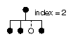 | |
Detaches child from the list and shifts the list to fill the vacant spot. Returns 1 if child was removed. Returns 0 if child was not found in the list. Note that the “removed” node is only detached, not deleted. |
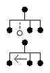 . | |
 |
pfGroup nodes can organize a database hierarchy either logically or spatially. For example, if your database contains a model of a town, a logical organization might be to group all house models under a single pfGroup. However, this kind of organization is less efficient than a spatial organization, which arranges geometry by location. A spatial organization improves culling and intersection performance; in the example of the town, spatial organization would consist of grouping houses with their local terrain geometry instead of with each other. Chapter 6 describes how to spatially organize your database for best performance.
The code fragment in Example 5-2 illustrates building a hierarchy using pfGroup nodes.
Example 5-2. Hierarchy Construction Using Group Nodes
scene = pfNewScene();

/* The following loop constructs a sample hierarchy by
 * adding children to several different types of group
 * nodes.  Notice that in this case the terrain was broken
 * up spatially into a 4x4 grid, and a switch node is used
 * to cause only one vehicle per terrain node to be
 * traversed.
 */

for(j = 0; j < 4; j++)
    for(i = 0; i < 4; i++)
    {
        pfGroup *spatial_terrain_block = pfNewGroup();
        pfSCS *house_offset = pfNewSCS();
        pfSCS *terrain_block_offset = pfNewSCS();
        pfDCS *car_position = pfNewDCS();
        pfDCS *tank_position = pfNewDCS();
        pfDCS *heli_position = pfNewDCS();
        pfSwitch *current_vehicle_type;
        pfGeode *heli, *car, *tank;

        pfAddChild(scene, spatial_terrain_block);
        pfAddChild(spatial_terrain_block,
                   terrain_block_offset);
        pfAddChild(spatial_terrain_block, house_offset);
        pfAddChild(spatial_terrain_block,
                   current_vehicle_type);
        pfAddChild(current_vehicle_type, car_position);
        pfAddChild(current_vehicle_type, tank_position);
        pfAddChild(current_vehicle_type, heli_position);
        pfAddChild(car_position, car);
        pfAddChild(tank_position, tank);
        pfAddChild(heli_position, heli);
    }

...

/* The following shows how one might use IRIS Performer to
 * manipulate the scene graph at run time by adding and
 * removing children from branch nodes in the scene graph.
 */

for(j = 0; j < 4; j++)
    for(i = 0; i < 4; i++)
    {
        pfGroup *this_terrain;
        this_terrain = pfGetChild(scene, j*4 + i);
        if (pfGetNumChildren(this_terrain) > 2)
            this_tank = pfGetChild(this_terrain, 2);
        if (is_tank_disable(this_tank))
        {
            pfRemoveChild(this_terrain, this_tank);
            pfAddChild(disabled_tanks, this_tank);
        }
    }
...
|
This section describes the basic concepts involved in working with nodes. It explains how shared instancing can be used to create multiple copies of an object, and how changes made to a parent node propagate down to its children. A sample program that illustrates these concepts is presented at the end of the chapter.
A scene graph is typically constructed at application initialization time by creating and adding new nodes to the graph. If a node is added to two or more parents it is termed instanced and is shared by all its parents. Instancing is a powerful mechanism that saves memory and makes modeling easier. libpf supports two kinds of instancing, which are described in the following sections.
Shared instancing is the result of simply adding a node to multiple parents. If an instanced node has children, then the entire subgraph rooted by the node is considered to be instanced. Each parent shares the node; thus, modifications to the instanced node or its subgraph are experienced by all parents. Shared instances can be nested—that is, an instance can itself instance other nodes.
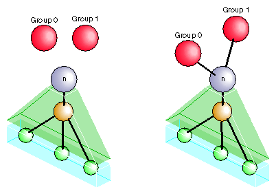
In the following sample code, group0 and group1 share a node:
pfAddChild(group0, node); pfAddChild(group1, node); |
Figure 5-2 shows the structure created by this code. Before the instancing operation, the two groups and the node to be shared all exist independently, as shown in the left portion of the figure. After the two function calls shown above, the two groups both reference the same shared hierarchy. (If the original groups referenced other nodes, those nodes would remain unchanged.) Note that each of the group nodes considers the shared hierarchy to be its own child.
In many situations shared instancing isn't desirable. Consider a subgraph that represents a model of an airplane with articulations for ailerons, elevator, rudder, and landing gear. Shared instances of the model result in multiple planes that share the same articulations. Consequently, it's impossible for one plane to be flying with its landing gear retracted while another is on a runway with its landing gear down.
Cloned instancing provides the solution to this problem by cloning—creating new copies of variable nodes in the subgraph. Leaf nodes containing geometry are not cloned and are shared to save memory. Cloning the airplane model generates new articulation nodes, which can be modified independently of any other cloned instance. The cloning operation, pfClone(), is actually a traversal and is described in detail in Chapter 6.
Figure 5-3 shows the result of cloned instancing. As in the previous figure, the left half of the drawing represents the situation before the operation, and the right half shows the result of the operation.
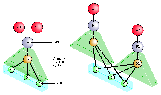
The cloned instancing operation constructs new copies of each internal node of the shared hierarchy, but uses the same shared instance of all the leaf nodes. In use, this is an important distinction, because the number of internal nodes may be relatively few, while the number and content of geometry-containing leaf nodes is often quite extensive.
Nodes G1 and G2 in Figure 5-3 are the groups that form the root nodes after the cloned instancing operation is complete. Node P is the parent or root node of the instanced object, and D is a dynamic coordinate system contained within it. Nodes A, B, and C are the leaf geometry nodes; they are shared rather than copied.
The code in Example 5-3 shows how to create cloned instances.
Example 5-3. Creating Cloned Instances
pfGroup *g1, *g2, *p; pfDCS *d; pfGeode *a, *b, *c; ... /* Create initial instance of scene hierarchy of p under * group g1: add a DCS to p, then add three pfGeode nodes * under the DCS. */ pfAddChild(g1,p); pfAddChild(p,d); pfAddChild(d,a); pfAddChild(d,b); pfAddChild(d,c); ... /* Create cloned instance version of p under g2 */ pfAddChild(g2, pfClone(p,0)); /* Notice that pfGeodes are cloned by instancing rather than * copying. Also notice that the second argument to * pfClone() is 0; that argument is currently required by * IRIS Performer to be zero. */ ... |
libpf uses bounding volumes for culling and to improve intersection performance. libpf computes bounding volumes for all nodes in a database hierarchy unless the bound is explicitly set by the application. The bounding volume of a branch node encompasses the spatial extent of all its children. libpf automatically recomputes bounds when children are modified.
By default, bounding volumes are dynamic; that is, libpf automatically recomputes them when children are modified. For instance, in Example 5-4 when the DCS is rotated nothing more needs to be done to update the bounding volume for g1.
Example 5-4. Automatically Updating a Bounding Volume
pfAddChild(g1,dcs); pfAddChild(dcs, helicopter); ... pfDCSRot(dcs, heading+10.0f, pitch,roll); ... pfDCSRot(dcs, heading, pitch - 5.0f, roll + 2.0f); |
In some cases, you may not want bounding volumes to be recomputed automatically. For example, in a merry-go-round with horses moving up and down, you know that the horses stay within a certain volume. Using pfNodeBSphere(), you can specify a bounding sphere within which the horse always remains and tell IRIS Performer that the bounding volume is “static”—not to be updated no matter what happens to the node's children. You can always force an update by setting the bounding volume to NULL with pfNodeBSphere(), as follows:
pfNodeBSphere(node, NULL, NULL, PFBOUND_STATIC); |
At the lowest level, within pfGeoSets, bounding volumes are maintained as axially-aligned boxes. When you add a pfGeoSet to a pfGeode or directly invoke pfGetGSetBBox() on the pfGeoSet, a bounding box is created for the pfGeoSet. Neither the bounding box of the pfGeoSet nor the bounding volume of the pfGeode is updated if the geometry changes inside the pfGeoSet. You can force an update by setting the pfGeoSet bounding box and then the pfGeode bounding volume to a NULL bounding box, as follows:
Recompute the pfGeoSet bounding box from the internal geometry:
pfGSetBBox(gset, NULL);
Recompute the pfGeode bounding volume from the bounding boxes of its pfGeoSets:
pfNodeBSphere(geode, NULL, PFBOUND_DYNAMIC);
This section describes the node types and the functions for working with each node type.
A pfScene is a root node that is the parent of a visual database. Use pfNewScene() to create a new scene node. Before the scene can be drawn, you must call pfChanScene(channel, scene) to attach it to a pfChannel.
Any nodes that are within the graph that is parented by a pfScene are culled and drawn once the pfScene is attached to a pfChannel. Because pfScene is a group, it uses pfGroup routines; however, a pfScene cannot be the child of any other node. The following statement adds a pfGroup to a scene:
pfAddChild(scene, root); |
In the simplest case, the pfScene is the only node you need to add. Once you have a pfPipe, pfChannel, and pfScene, you have all the necessary elements for generating graphics using IRIS Performer.
pfScene nodes may specify a global pfGeoState that all other pfGeoStates in nodes below the pfScene will inherit from. Specification of this scene pfGeoState is done via the function pfSceneGState(). This functionality allows for the subtle optimization of pushing the most frequently used pfGeoState attributes for a particular scene graph into a global state and having the individual states inherit these attributes rather than specify them. This can save Performer work during culling (by having to `unwrap' fewer pfGeoStates) and thus possibly increase frame rate. There are several database utility functions in libpfdu designed to help with this optimization. pfdMakeSceneGState() returns an `optimal' pfGeoState based on a list of pfGeoStates. pfdOptimizeGStateList() takes an existing global pfGeoState, a new global pfGeoState, and a list of pfGeoState's that should be optimized and cause all attributes of pfGeoStates in the list of pfGeoStates to be inherited if they are the same as the attribute in the new global pfGeoState. Lastly pfdMakeSharedScene() will cause this optimization to happen for all of the pfGeoStates under the pfScene that was passed into the function. For more information on pfGeoStates see Chapter 10, “libpr Basics,” which discusses libpr in more detail. For more information of the creation and optimization of databases see Chapter 9, “Importing Databases,” which discusses building database converters and libpfdu.
A pfSCS is a branch node that represents a static coordinate system. A pfSCS node contains a fixed modeling transformation matrix that cannot be changed once it is created. pfSCS nodes are useful for positioning models within a database. For example, a house that is modeled at the origin should be placed in the world with a pfSCS because houses rarely move during program execution.
Use pfNewSCS(matrix) to create a new pfSCS using the transformation defined by matrix. To find out what matrix was used to create a given pfSCS, call pfGetSCSMat().
For best graphics performance, matrices passed to pfSCS nodes (and the pfDCS node type described in the next section) should be orthonormal (translations, rotations, and uniform scales). Nonuniform scaling requires renormalization of normals in the graphics pipe. Projections and other non-affine transformations are not supported.
While pfSCS nodes are useful in modeling, using too many of them can reduce culling, rendering, and intersection performance. For this reason, libpf provides the pfFlatten() traversal. pfFlatten() will traverse a scene graph and apply static transformations directly to geometry to eliminate the overhead associated with managing the transformations. pfFlatten() is described in detail in Chapter 6, “Database Traversal.”
A pfDCS is a branch node that represents a dynamic coordinate system. Use a pfDCS when you want to apply an initial transformation to a node and also change the transformation during the application. Use a pfDCS to articulate moving parts and to show object motion.
Use pfNewDCS() to create a new pfDCS. The initial transformation of a pfDCS is the identity matrix. Subsequent transformations are set by specifying a new transformation matrix, or by replacing the rotation, scale, or translation in the current transformation matrix. The pfDCS transforms each child C(i) to C(i)*Scale*Rotation*Translation.
Table 5-3 lists functions for manipulating a pfDCS, including rotating, scaling, and translating the children of the pfDCS.
Table 5-3. DCS Transformations
Function Name | Description |
|---|---|
pfNewDCS | |
pfDCSTrans | |
Set the rotation transformation to h, p, r. | |
pfDCSCoord | |
Scale by a uniform scale factor. | |
Use a matrix for transformations. | |
pfGetDCSMat |
A pfSwitch is a branch node that selects one, all, or none of its children. Use pfNewSwitch() to return a handle to a new pfSwitch. To select all the children, use the PFSWITCH_ON argument to pfSwitchVal(). Deselect all the children (turning the switch off) using PFSWITCH_OFF. To select a single child, give the index of the child from the child list. To find out the current value of a given switch, call pfGetSwitchVal(). Example 5-5 (in the “pfSequence Nodes” section) illustrates a use of pfSwitch nodes to control pfSequence nodes.
A pfSequence is a pfGroup that sequences through a range of its children, drawing each child for a specified duration. Each child in a sequence can be thought of as a frame in an animation. A sequence can consist of any number of children, and each child has its own duration. You can control whether an entire sequence repeats from start to end, repeats from end to start, or terminates.
Use pfNewSeq() to create and return a handle to a new pfSequence. Once the pfSequence has been created, use the group function pfAddChild() to add the children that you want to animate.
Table 5-4 describes the functions for working with pfSequences.
Table 5-4. pfSequence Functions
Example 5-5 demonstrates a possible use of both switches and sequences. First, sequences are set up to contain animation sequences for explosions, fire, and smoke; then a switch is used to control which sequences are currently active.
Example 5-5. Using pfSwitch and pfSequence Nodes
pfSwitch *s;
pfSequence *explosion1_seq, *explosion2_seq, *fire_seq,
           *smoke_seq;
...
s = pfNewSwitch();
explosion1_seq = pfNewSeq();
explosion2_seq = pfNewSeq();
fire_seq = pfNewSeq();
smoke_seq = pfNewSeq();

pfAddChild(s, explosion1_seq);
pfAddChild(s, explosion2_seq);
pfAddChild(s, fire_seq);
pfAddChild(s, smoke_seq);
pfSwitchVal(s, PFSWITCH_OFF);
...
if (direct_hit)
{
    pfSwitchVal(s, PFSWITCH_ON); /* Select all sequences */

    /* Set first explosion sequence to go double normal
     * speed and repeat 3 times. */
    pfSeqMode(explosion1_seq, PFSEQ_START);
    pfSeqDuration(explosion1_seq, 2.0f, 3);

    /* Set second explosion sequence to display first child
     * of sequence for 2 seconds before continuing. */
    pfSeqMode(explosion2_seq, PFSEQ_START);
    pfSeqTime(explosion2, 0.0f, 2.0f);

    /* Set fire to wait on first frame of sequence until .3
     * seconds after second explosion. */
    pfSeqMode(fire_seq, PFSEQ_START);
    pfSeqTime(fire_seq, 0.0f, 2.3f);

    /* Set smoke to wait until .1 seconds after fire. */
    pfSeqMode(smoke_seq, PFSEQ_START);
    pfSeqTime(smoke_seq, 0.0f, 2.4f);
}
else if (explosion && (expl_type == 0))
{
    pfSeqMode(explosion1_seq, PFSEQ_START);
    pfSwitchVal(s, 0);
}
else if (explosion && (expl_type == 1))
{
    pfSeqMode(explosion2_seq, PFSEQ_START);
    pfSwitchVal(s, 1);
}
else if (fire_is_burning)
{
    pfSeqMode(fire_seq, PFSEQ_START);
    pfSwitchVal(s, 2);
}
else if (smoking)
{
    pfSeqMode(smoke_seq, PFSEQ_START);
    pfSwitchVal(s, 3);
}
else
    pfSwitchVal(s, PFSWITCH_OFF);
...
|
A pfLOD is a level-of-detail node. Level-of-detail switching is an advanced concept that is discussed in Chapter 7, “Frame and Load Control.” A level-of-detail node specifies how its children are to be displayed, based on the visual range from the channel's viewpoint. Each child has a defined range, and the entire pfLOD has a defined center.
Table 5-5 describes the functions for working with pfLODs.
Function | Description |
|---|---|
pfNewLOD | |
pfLODRange | |
pfGetLODRange | |
pfLODCenter | |
pfGetLODCenter | |
pfLODTransition | Set the width of a specified transition. |
pfGetLODTransition | Get the width of a specified transition. |
A pfLayer is a leaf node that resolves the visual priority of coplanar geometry. A pfLayer allows the application to define a set of base geometry and a set of layer geometry (sometimes called decal geometry). The base geometry and the decal geometry should be coplanar, and the decal geometry must lie within the extent of the base polygons.
Table 5-6 describes the functions for working with pfLayers.
Function | Description |
|---|---|
pfNewLayer | |
pfLayerMode | |
pfGetLayerMode | |
pfLayerBase | |
pfGetLayerBase | |
pfLayerDecal | |
pfGetLayerDecal |
pfLayer nodes can be used to overlay any sort of markings on a given polygon and are important to avoid flimmering. Example 5-6 demonstrates how to display runway markings as a decal above of a coplanar runway. This example uses the performance mode PFDECAL_BASE_FAST for layering; as described in the reference page, other available modes are PFDECAL_BASE_HIGH_QUALITY, PFDECAL_BASE_DISPLACE, and PFDECAL_BASE_STENCIL.
Example 5-6. Marking a Runway With a pfLayer Node
pfLayer *layer; pfGeode *runway, *runway_markings; ... /* avoid flimmering of runway and runway_markings */ layer = pfNewLayer(); pfLayerBase(layer, runway); pfLayerDecal(layer, runway_markings); pfLayerMode(layer, PFDECAL_BASE_FAST); |
A pfLightPoint is a leaf node that represents a light point or set of light points. Light points don't provide overall illumination for a scene; rather, they are discrete points that emanate light, such as street lights and runway edge lights. A pfLightPoint can contain one or several light points that share common attributes, such as color, intensity, direction, and shape.
The pfLPointState mechanism provides a more comprehensive approach to light point simulation. pfLightPoint nodes are retained only for backward compatibility with previous releases of IRIS Performer. New applications should use pfLPointStates.
Table 5-7 describes the functions for working with pfLightPoints.
Table 5-7. pfLightPoint Functions
Function | Description |
|---|---|
pfNewLPoint | |
pfLPointSize | |
pfGetLPointSize | |
pfLPointColor | |
pfGetLPointColor | |
pfLPointRot | |
pfGetLPointRot | |
pfLPointShape | |
pfGetLPointShape | |
pfLPointPos | |
pfGetLPointPos |
Example 5-7 demonstrates some operations on light points.
Example 5-7. Setting Up Light Points
pfLightPoint *lp; pfVec4 red; pfVec3 pos; ... /* create a string of ten light points */ lp = pfNewLPoint(10); /* set the size in screen pixels for each light */ pfLPointSize(lp, 1.0f); /* set the light point color */ pfSetVec4(red, 1.0f, 0.0f, 0.0f, 1.0f); pfLPointColor(lp, red); /* set the direction the light points face */ pfLPointRot(lp, 270.0f, 30.0f, 0.0f); /* Set the position of light point 5 */ pfSetVec3(pos,10.0f,10.0f,0.0f); pfLPointPos(lp, 5, pos); ... |
A pfLightSource, unlike a pfLightPoint, provides light for a scene's geometry but is itself invisible.
Illuminating the geometry in a scene graph requires a light source which the graphics hardware uses to compute surface shading. While the libpr primitive pfLight (see “Lighting”) provides a hardware light source, it isn't a pfNode and so cannot benefit from the features provided by a scene graph, such as transformation hierarchy, switches, and sequenced animations.
The pfLightSource node allows you to add lighting information to your scene graph. pfLightSource is multiply inherited; it's derived from both pfNode and pfLight, so you can use a pfLightSource* as an argument to a function that requires a pfNode* or pfLight*, as illustrated in Example 5-8.
Example 5-8. pfLightSource Pointers and Multiple Inheritance
pfLightSource *lsource = pfNewLSource(); /* Set color to red */ pfLightColor(lsource, 1.0f, 0.0f, 0.0f); /* Add light source to scene */ pfAddChild(scene, lsource); |
In this example lsource is the pfLight* argument to pfLightColor() and the pfNode* argument to pfAddChild().
The scope, or area of influence, of a pfLightSource is global and isn't affected by its location in the scene graph unless it is culled during the cull traversal. If not culled, it illuminates everything in the pfScene of which it is a member and doesn't affect anything outside the pfScene besides custom geometry rendered by the application in a channel draw callback.
A pfLightSource does inherit transformations and switch values from its parents in the scene graph. Thus you can attach a light source to a moving object and easily turn it on and off. Example 5-9 shows how you might configure the headlights of a moving car:
Example 5-9. Car Headlights as pfLightSource Nodes
static pfNode* initCarGeometry(void);

    pfDCS *car = pfNewDCS();
    pfLightSource *leftHeadlight = pfNewLSource();
    pfLightSource *rightHeadlight = pfNewLSource();

    /*
     * Set white light color. This isn't really necessary
     * since pfLightSources are white by default.
     */
    pfLightColor(leftHeadlight, 1.0f, 1.0f, 1.0f);
    pfLightColor(rightHeadlight, 1.0f, 1.0f, 1.0f);

    /* Position headlights on front of car as local light
     * sources. */
    pfLightPos(leftHeadlight, -1.0f, 0.0f, 0.0f, 1.0f);
    pfLightPos(rightHeadlight, 1.0f, 0.0f, 0.0f, 1.0f);

    /*
     * Configure headlights as spotlights pointing in same
     * direction as car: +Y direction. Set the spotlights
     * to have falloff of 1 and angular spread of 30 degrees.
     */
    pfSpotLightDir(leftHeadlight, 0.0f, 1.0f, 0.0f);
    pfSpotLightCone(leftHeadlight, 1.0f, 30.0f);
    pfSpotLightDir(rightHeadlight, 0.0f, 1.0f, 0.0f);
    pfSpotLightCone(rightHeadlight, 1.0f, 30.0f);

    /*
     * Turn on headlights. This isn't really necessary since
     * pfLightSources are on by default.
     */
    pfLightOn(leftHeadlight);
    pfLightOn(rightHeadlight);

    /* Create car geometry and add to car DCS */
    pfAddChild(car, initCarGeometry());

    /* Attach headlights to moving car. */
    pfAddChild(car, leftHeadlight);
    pfAddChild(car, rightHeadlight);
|
In Example 5-9, both the position and spotlight direction of the light sources are transformed by the combination of the car's pfDCS and all other pfDCS or pfSCS nodes above it in the scene graph. Note that we specified to pfLightPos() that the pfLightSource have a location with the fourth coordinate nonzero. This defines a local light source; an infinite light source has zero for its fourth coordinate. An infinite light source has only a direction, not a location; it emits parallel rays because it is considered infinitely far away. (The sun, for example, is approximated as an infinite light source.) Transformations change only the direction of an infinite light source, not its position.
Also note in Example 5-9 that a pfSwitch isn't necessary to turn a pfLightSource on or off; you can directly switch a pfLightSource with pfLightOn() and pfLightOff().
pfLightSources are treated specially when drawing a scene graph. All paths leading to pfLightSources in a scene are traversed before the scene is traversed. (For information about paths, see “Paths Through the Scene Graph” in Chapter 6.) This special, initial traversal guarantees that the graphics hardware will be configured with all pfLightSources so that they will affect all geometry in the scene. In addition, these light sources are set up before the channel draw callback is invoked, so they affect all custom geometry rendered by the application both before and after pfDraw(). (See “pfNode Cull and Draw Callbacks” in Chapter 6 for more on callbacks.)
By default, pfLightSource traversal is enabled and carried out by the cull traversal. If you wish to bypass this traversal and thereby ignore all pfLightSources in your scene, then set the PFCULL_IGNORE_LSOURCES bit in the mode passed to pfChanTravMode() for the PFTRAV_CULL traversal.
A pfLightSource has no default bounding volume, though you can assign it one with pfNodeBSphere(). If a pfLightSource is assigned a bounding volume it becomes subject to view frustum culling and will be discarded if it is completely outside the view frustum of the pfChannel. If the light source is found to be within the view frustum or it has an empty bounding volume (the default), the pfLightSource will affect everything in view. By setting the appropriate bounding sphere it is possible to roughly specify a light source with limited influence.
Table 5-8 describes the functions for working with pfLightSources.
Table 5-8. pfLightSource Functions
pfGeode is short for geometry node and is the primary node for defining geometry in libpf. A pfGeode contains a list of geometry structures called pfGeoSets, which are part of the IRIS Performer libpr library. pfGeoSets encapsulate graphics state and geometry and are described in the “Geometry Sets” section of Chapter 10, “libpr Basics.” It is important to understand that pfGeoSets are not nodes but are simply elements of a pfGeode.
Table 5-9 describes the functions for working with pfGeodes.
Function | Description |
|---|---|
pfNewGeode | |
pfAddGSet | |
pfRemoveGSet | |
pfInsertGSet | |
pfReplaceGSet | |
pfGetGSet | |
pfGetNumGSets |
Example 5-10 shows how to attach several pfGeoSets to a pfGeode.
Example 5-10. Adding pfGeoSets to a pfGeode
pfGeode *car1; pfGeoSet *muffler, *frame, *windows, *seats, *tires; muffler = read_in_muffler_geometry(); frame = read_in_frame_geometry(); seats = read_in_seat_geometry(); tires = read_in_tire_geometry(); pfAddGSet(car1, muffler); pfAddGSet(car1, frame); pfAddGSet(car1, seats); ... |
A pfText node is libpf leaf node that contains a set of libpr pfStrings that should be rendered based on the libpf cull and draw traversals. In this sense a pfText is similar to a pfGeode except that it renders 3-dimensional text through the libpr pfString and pfFont mechanisms rather than rendering standard 3-dimensional geometry via libpr pfGeoSet and pfGeoState functionality. pfText nodes are useful for displaying 3-dimensional text and other collections of geometry from a fixed index list. Table 5-10 lists the major pfText functions.
Function | Description |
|---|---|
pfNewText | |
pfAddString | |
pfRemoveString | |
pfInsertString | |
pfReplaceString | |
pfGetString | |
pfGetNumStrings |
Using the pfText facility is easy. Example 5-11 shows how a pfFont is defined, how pfStrings are created that reference that font, and then how those pfStrings are added to a pfText node for display. See the description of pfStrings and pfFonts in Chapter 10, “libpr Basics,” for information on setting up individual strings to input into a pfText node
int nStrings,i;
char tmpBuf[8192];
char fontName[128];
pfFont *fnt = NULL;
/* Create a new text node
pfText *txt = pfNewText();

/* Read in font using libpfdu utility function */
scanf(“%s”,fontName);
fnt = pfdLoadFont(“type1”,fontName,PFDFONT_EXTRUDED);

/* Cant render pfText or libpr pfString without a pfFont */
if (fnt == NULL)
    pfNotify(PFNFY_WARN,PFNFY_PRINT,
             ”No Such Font - %s\n”,fontName);

/* Read nStrings text strings from standard input and */
/* Attach them to a pfText */
scanf(“%d”,&nStrings);
for(i=0;i<nStrings;i++)
{
    char c;
    int j=0;
    int done = 0;
    pfString *curStr = NULL;

    while(done < 2) /* READ STRING - END on `||' */
    {
        c = getchar();
        if (c == `|')
            done++;
        else
            done = 0;
        tmpBuf[j++] = c;
    }
    tmpBuf[PF_MAX2(j-2,0)] = `\0';

/* Create new libpr pfString structure to attach to pfText */
    curStr = pfNewString(pfGetSharedArena());

/* Set the font for the libpr pfString */
    pfStringFont(curStr, fnt);

/* Assign the char string to the pfString */
    pfStringString(curStr, tmpBuf);

/* Add this libpr pfString to the pfText node */
/* Like adding a libpr pfGeoSet to a pfGeode */
    pfAddString(txt, curStr);
}
pfAddChild(SceneGroup, txt);
|
A pfBillboard is a pfGeode that rotates its children's geometry to follow the view direction or the eyepoint. Billboards are useful for portraying complex objects that are roughly symmetrical in one or more axes. The billboard rotates to always present the same image to the viewer using far fewer polygons than a solid model uses. In this way, billboards reduce both transformation and pixel fill demands on the graphics subsystem at the expense of some additional host processing. A classic example is a textured billboard of a single quadrilateral representing a tree.
Because a pfBillboard is also a pfGeode, you can pass a pfBillboard argument to any pfGeode routine. To add geometry, call pfAddGSet() (see “pfGeode Nodes”). Each pfGeoSet in the pfBillboard is treated as a separate piece of billboard geometry; each one turns so that it always faces the eye point.
pfBillboards can be either constrained to rotate about an axis, as is done for a tree or a lamp post, or constrained only by a point, as when simulating a cloud or a puff of smoke. Specify the rotation mode by calling pfBboardMode(); specify the rotational axis by calling pfBboardAxis(). Since rotating the geometry to the eyepoint doesn't fully constrain the orientation of a point-rotating billboard, modes are available to use the additional degree of freedom to align the billboard in eye space or world space. Usually the normals of billboards are specified to be parallel to the rotational axis to avoid lighting anomalies.
pfFlatten() is highly recommended for billboards. If a billboard lies beneath a pfSCS or pfDCS, an additional transformation is done for each billboard. This can have a substantial performance impact on the cull process, where billboards are transformed.
Table 5-11 describes the functions for working with pfBillboards.
Table 5-11. pfBillboard Functions
Function | Description |
|---|---|
pfNewBboard | |
pfBboardPos | |
pfGetBboardPos | |
pfBboardAxis | |
pfGetBboardAxis | |
pfBboardMode | |
pfGetBboardMode |
Example 5-12 demonstrates the construction of a pfBillboard node. The code can be found in /usr/share/Performer/src/pguide/libpf/C/billboard.c.
Example 5-12. Setting Up a pfBillboard
static pfVec2 BBTexCoords[] ={{0.0f, 0.0f},
                              {1.0f, 0.0f},
                              {1.0f, 1.0f},
                              {0.0f, 1.0f}};

static pfVec3 BBVertCoords[4] = /* XZ plane for pt bboards */
                         {{-0.5f, 0.0f, 0.0f},
                          { 0.5f, 0.0f, 0.0f},
                          { 0.5f, 0.0f, 1.0f},
                          {-0.5f, 0.0f, 1.0f}};

static pfVec3 BBAxes[4] = {{1.0f, 0.0f, 0.0f}, /* X */
                           {0.0f, 1.0f, 0.0f}, /* Y */
                           {0.0f, 0.0f, 1.0f}, /* Z */
                           {0.0f, 0.0f, 1.0f}}; /*world Zup*/

static int BBPrimLens[] = { 4 };

static pfVec4 BBColors[] = {{1.0, 1.0, 1.0, 1.0}};


/* Convert static data to pfMalloc'ed data */
static void*
memdup(void *mem, size_t bytes, void *arena)
{
    void *data = pfMalloc(bytes, arena);
    memcpy(data, mem, bytes);
    return data;
}

/* For pedagogical use only. Reasonable performance
 * requires more then one pfGeoSet per pfBillboard.
 */

pfBillboard*
MakeABill(pfVec3 pos, pfGeoState *gst, long bbType)
{
    pfGeoSet *gset;
	    pfGeoState *gstate;
    pfBillboard *bill;
    void *arena = pfGetSharedArena();

	    gset = pfNewGSet(arena);
	    gstate = pfNewGState(arena);

    pfGStateMode(gstate, PFSTATE_ENLIGHTING, PF_OFF);
	    pfGStateMode(gstate, PFSTATE_ENTEXTURE, PF_ON);
    /*.... Create/load texture map for billboard... */
    pfGStateAttr(gstate, PFSTATE_TEXTURE, texture);
    pfGSetGState(gset, gstate);

    pfGSetAttr(gset, PFGS_COORD3, PFGS_PER_VERTEX,
	        memdup(BBVertCoords, sizeof(BBVertCoords), arena),
        NULL);
    pfGSetAttr(gset, PFGS_TEXCOORD2, PFGS_PER_VERTEX,
	        memdup(BBTexCoords, sizeof(BBTexCoords), arena),
        NULL);

	    pfGSetAttr(gset, PFGS_COLOR4, PFGS_OVERALL,
	        memdup(BBColors, sizeof(BBColors), arena),
        NULL);

    pfGSetPrimLengths(gset,
        (int*)memdup(BBPrimLens, sizeof(BBPrimLens), arena));
    pfGSetPrimType(gset, PFGS_QUADS);
    pfGSetNumPrims(gset, 1);
    pfGSetGState(gset, gst);

    bill = pfNewBboard();
    switch (bbType)
    {
    case PF_X: /* axial rotate */
    case PF_Y:
    case PF_Z:
        pfBboardAxis(bill, BBAxes[bbType]);
        pfBboardMode(bill, PFBB_ROT, PFBB_AXIAL_ROT);
        break;
    case 3: /* point rotate */
        pfBboardAxis(bill, BBAxes[bbType]);
        pfBboardMode(bill, PFBB_ROT, PFBB_POINT_ROT_WORLD);
        break;
    }
    pfAddGSet(bill, gset);
    pfBboardPos(bill, 0, pos);

    return bill;
}
|
A pfPartition is a pfGroup that organizes the scene graphs of its children into a static data structure that can be more efficient for intersections. Currently, partitions are only useful for data that lies more or less on an XY plane, such as terrain. A pfPartition would therefore be inappropriate for a skyscraper model.
Partition construction comes in two phases. After a piece of the scene graph has been placed under the pfPartition, pfBuildPart() examines the spatial arrangement of geometry beneath the pfPartition and determines an appropriate origin and spacing for the grid. Because the search is exhaustive, this examination can be time-consuming the first time through. Once a good partitioning is determined, the search space can be restricted for future database loads using the partition attributes.
The second phase is invoked by pfUpdatePart(), which distributes the pfGeoSets under the pfPartition into cells in the spatial partition created by pfBuildPart(). pfUpdatePart() needs to be called if any geometry under the pfPartition node changes.
During intersection traversal, the segments in a pfSegSet (see “Intersection Requests: pfSegSets” in Chapter 6) are scan-converted onto the grid, yielding faster access to those pfGeoSets that potentially intersect the segment. A pfPartition can be made to function as a normal pfGroup during intersection traversal by OR-ing PFTRAV_IS_NO_PART into the intersection traversal mode in the pfSegSet.
Table 5-12 describes the functions for working with pfPartitions.
Table 5-12. pfPartition Functions
Function | Description |
|---|---|
pfNewPart | |
pfPartVal | |
pfGetPartVal | |
pfPartAttr | |
pfGetPartAttr | |
pfBuildPart | |
pfUpdatePart | |
pfGetPartType |
Example 5-13 demonstrates setting up and using a pfPartition node.
Example 5-13. Setting Up a Partition
pfGroup *terrain;
pfPartition *partition;
pfScene *scene;

...

terrain = read_in_grid_aligned_terrain();

...

/* create a default partitioning of a terrain grid */
partition = pfNewPart();
pfAddChild(scene, partition);
pfAddChild(partition, terrain);
pfBuildPart(partition);

...

/* use the partitions to perform efficient intersections
 * of sets of segments with the terrain */
for(i = 0; i < numVehicles; i++)
    pfNodeIsectSegs(partition, vehicle_segment_set[i],
                    hit_struct);
...
|
The sample program shown in Example 5-14 demonstrates scene graph construction, shared instancing, and transformation inheritance. The program uses IRIS Performer objects and functions that are described fully in later chapters.
This program reads the names of two objects from the command line, although defaults are supplied if file names are not given. These files are loaded and a second instance of each object is created. In each case, this instance is made to orbit the original object, and the second pair are also placed in orbit around the first. This program is “inherit.c” and is part of the suite of IRIS Performer Programmer's Guide example programs.
Example 5-14. Inheritance demonstration program
/*
 * inherit.c - transform inheritance example
 */

#include <math.h>
#include <Performer/pf.h>
#include <Performer/pfdu.h>

int
main(int argc, char *argv[])
{
    pfPipe *pipe;
    pfPipeWindow *pw;
    pfScene *scene;
    pfChannel *chan;
    pfCoord view;
    float z, s, c;
    pfNode	 *model1, *model2;
    pfDCS	 *node1, *node2;
    pfDCS	 *dcs1, *dcs2, *dcs3, *dcs4;
    pfSphere sphere;
    char	 *file1, *file2;

    /* choose default objects of none specified */
    file1 = (argc > 1) ? argv[1] : “blob.nff”;
    file2 = (argc > 1) ? argv[1] : “torus.nff”;

    /* Initialize Performer */
    pfInit();

    pfFilePath(
    “.”
	    “:./data”
	    “:../data”
	    “:../../data”
	    “:../../../data”
	    “:../../../../data”
	    “:/usr/share/Performer/data”);

    /* Single thread for simplicity */
    pfMultiprocess(PFMP_DEFAULT);

    /* Load all loader DSO's before pfConfig() forks */
    pfdInitConverter(file1);
    pfdInitConverter(file2);

    /* Configure */
    pfConfig();

    /* Load the files */
    if ((model1 = pfdLoadFile(file1)) == NULL)
    {
        pfExit();
        exit(-1);
    }
    if ((model2 = pfdLoadFile(file2)) == NULL)
    {
        pfExit();
        	exit(-1);
    }

    /* scale models to unit size */
    node1 = pfNewDCS();
    pfAddChild(node1, model1);
    pfGetNodeBSphere(model1, &sphere);
    if (sphere.radius > 0.0f)
        pfDCSScale(node1, 1.0f/sphere.radius);

    node2 = pfNewDCS();
    pfAddChild(node2, model2);
    pfGetNodeBSphere(model2, &sphere);
    if (sphere.radius > 0.0f)
        pfDCSScale(node2, 1.0f/sphere.radius);

    /* Create the hierarchy */
    dcs4 = pfNewDCS();
    pfAddChild(dcs4, node1);
    pfDCSScale(dcs4, 0.5f);

    dcs3 = pfNewDCS();
    pfAddChild(dcs3, node1);
    pfAddChild(dcs3, dcs4);

    dcs1 = pfNewDCS();
    pfAddChild(dcs1, node2);

    dcs2 = pfNewDCS();
    pfAddChild(dcs2, node2);
    pfDCSScale(dcs2, 0.5f);
    pfAddChild(dcs1, dcs2);

    scene = pfNewScene();
    pfAddChild(scene, dcs1);
    pfAddChild(scene, dcs3);
    pfAddChild(scene, pfNewLSource());

    /* Configure and open GL window */
    pipe = pfGetPipe(0);
    pw = pfNewPWin(pipe);
    pfPWinType(pw, PFPWIN_TYPE_X);
    pfPWinName(pw, “IRIS Performer”);
    pfPWinOriginSize(pw, 0, 0, 500, 500);
    pfOpenPWin(pw);

    chan = pfNewChan(pipe);
    pfChanScene(chan, scene);

    pfSetVec3(view.xyz, 0.0f, 0.0f, 15.0f);
    pfSetVec3(view.hpr, 0.0f, -90.0f, 0.0f);
    pfChanView(chan, view.xyz, view.hpr);

    /* Loop through various transformations of the DCS's */
    for (z = 0.0f; z < 1084; z += 4.0f)
    {
        pfDCSRot(dcs1,
        (z < 360) ? (int) z % 360 : 0.0f,
        (z > 360 && z < 720) ? (int) z % 360 : 0.0f,
        (z > 720) ? (int) z % 360 : 0.0f);

        pfSinCos(z, &s, &c);
        pfDCSTrans(dcs2, 1.0f * c, 1.0f * s, 0.0f);

        pfDCSRot(dcs3, z, 0, 0);
        pfDCSTrans(dcs3, 4.0f * c, 4.0f * s, 4.0f * s);
        pfDCSRot(dcs4, 0, 0, z);
        pfDCSTrans(dcs4, 1.0f * c, 1.0f * s, 0.0f);

        pfFrame();
    }

    /* show objects static for three seconds */
    sleep(3);

    pfExit();
    exit(0);
}
|