libpf is a visual-database processing and rendering system. The visual database has at its root a pfScene (as described in Chapter 5 and Chapter 6). A pfScene is viewed by a pfChannel, which is rendered to a pfPipeWindow by a pfPipe. This chapter describes how to use pfPipes, pfPipeWindows, and pfChannels.
This section describes rendering pipelines (pfPipes) and their implementation in IRIS Performer. Each rendering pipeline draws into one or more windows (pfPipeWindows) associated with a single Geometry Pipeline. A minimum of one rendering pipeline is required, although it is possible to have more than one.
This rendering pipeline comprises three primary functional stages:
Figure 4-1 shows the process flow for a single-pipe system. The application constructs and modifies the scene definition (a pfScene) associated with a channel. The traversal process associated with that channel's pfPipe then traverses the scene graph, building an IRIS Performer libpr display list. As shown in the figure, this display list is used as input to the draw process that performs the actual graphics library actions required to draw the image.

IRIS Performer also provides additional processes for application processing tasks, such as database loading and intersection traversals, but these processes are per-application and are asynchronous to the software rendering pipeline(s).
An IRIS Performer application renders images using one or more pfPipes. Each pfPipe represents an independent software-rendering pipeline. Most IRIS systems contain only one Geometry Pipeline, so a single pfPipe is usually appropriate. This single pipeline is often associated with a window that occupies the entire display surface.
Alternative configurations include Onyx systems with RealityEngine2™ graphics (allowing up to three Geometry Pipelines). Applications can render into multiple windows, each of which is connected to a single Geometry Pipeline through a pfPipe rendering pipeline.
Figure 4-2 shows the process flow for a dual-pipe system. Notice both the differences and similarities between these two figures. Each pipeline (pfPipe) is independent in multiple-pipe configurations; the traversal and draw tasks are separate, as are the libpr display lists that link them. In contrast, these pfPipes are controlled by the same application process, and in many situations access the same shared scene definition.

Each of these stages can be combined into a single IRIX process or split into multiple processes (pfMultiprocess) for enhanced performance on multiple CPU systems. Multiprocessing and multiple pipes are advanced topics that are discussed in “Successful Multiprocessing With IRIS Performer” in Chapter 7.
pfMultipipe() specifies the number of pfPipes desired. pfMultiprocess() specifies the multiprocessing mode used by all pfPipes. These two routines are discussed further in“Successful Multiprocessing With IRIS Performer” in Chapter 7.
pfPipes and their associated processes are created when pfConfig() is called. They exist for the duration of the application. After pfConfig(), the application can get handles to the created pfPipes using pfGetPipe(). The argument to pfGetPipe() indicates which pfPipe to return and is an integer between 0 and numPipes-1, inclusive. The pfPipe handle is then used for further configuration of the pfPipe.
You may have application state associated with pfPipe stages and processes that need special initialization. For this purpose, you may provide a stage configuration callback for each pfPipe stage using pfStageConfigFunc(pipe, stageMask, configFunc) and specify the pfPipe, the stage bitmask (including one or more of PFPROC_APP, PFPROC_CULL, and PFPROC_DRAW), and your stage configuration callback routine. At any time, you may call the function pfConfigStage() from the application process to trigger the execution of your stage configuration callback in the process associated with that pfPipe's stage. The stage configuration callback will be invoked at the start of that stage within the current frame (the current frame in the application process, and subsequent frames through the cull and draw phases of the software rendering pipeline). Use a pfStageConfigFunc() callback function to configure performer processes not associated with pfPipes, such as the database process, PFPROC_DBASE, and the intersection process, PFPROC_ISECT. A common process initialization task for real-time applications is the selection and/or specification of a CPU on which to run.
The final part of pfPipe initialization is the specification of the graphics hardware pipeline (or screen) and the creation of a window on that screen. The screen of a pfPipe can be set explicitly using pfPipeScreen(). Under single pipe operation, pfPipes can also inherit the screen of their first opened window. Under multipipe operation, the screen of all pfPipes must be determined before the pipes are configured by pfConfigStage() or the first call to pfFrame(). Once the screen of a pfPipe has been set, it cannot be changed. All windows of a pfPipe must be opened on the same screen. A graphics window is associated with a pfPipe through the pfPipeWindow mechanism, which is the subject of the next section, “Using pfPipeWindows.” If you do not create a pfPipeWindow, IRIS Performer will automatically create and open a full screen window with a default configuration for your pfPipe.
Once you create and initialize a pfPipe, you can query information about its configuration parameters. pfGetPipeScreen() returns the index number of the hardware pipeline for the pfPipe, starting from zero. On single-pipe systems the return value will be zero. If no screen has been set, the return value will be (-1). pfGetPipeSize() returns the full screen size, in pixels, of the rendering area associated with a pfPipe.
The sample source code shipped with IRIS Performer includes several simple examples of pfPipe use in both C and C++. Specifically, look at the following examples under the C and C++ directories in /usr/share/Performer/src/pguide/libpf/, such as hello.c, simple.c, and multipipe.c.
Example 4-1 illustrates the basics of using pipes. The code in this example is adapted from IRIS Performer sample programs.
main()
{
	     int i;

     /* Initialize IRIS Performer */
     pfInit();
    /* Set number of pfPipes desired -- THIS MUST BE DONE
     * BEFORE CALLING pfConfig().
     */
    pfMultipipe(NumPipes);
    /* set multiprocessing mode */
    pfMultiprocess(ProcSplit);
    ...
    /* Configure IRIS Performer and fork extra processes if
     * configured for multiprocessing.
     */
    pfConfig();
     ...

    /* Optional custom mapping of pipes to screens.
     * This is actually the reverse as the default.
     *//
     for (i=0; i < NumPipes; i++)
          pfPipeScreen(pfGetPipe(i), NumPipes-(i+1));
    {
        /* set up optional DRAW pipe stage config callback */
        pfStageConfigFunc(-1 /* selects all pipes */,
                      PFPROC_DRAW /* stage bitmask */,
                      ConfigPipeDraw /* config callback */);
        /* Config func should be done next pfFrame */
        pfConfigStage(i, PFPROC_DRAW);
    }
    InitChannels();
    ...
    /* trigger the configuration and opening of pfPipes
     * and pfWindows
     */
    pfFrame();

    /* Application's simulation loop */
    while(!SimDone())
    {
    ...
    }
}

/* CALLBACK FUNCTIONS FOR PIPE STAGE INITIALIZATION */
void
ConfigPipeDraw(int pipe, uint stage)
{
/* Application state for the draw process can be initialized
 * here. This is also a good place to do real-time
 * configuration for the drawing process, if there is one.
 * There is no graphics state or pfState at this point so no
 * rendering calls or pfApply*() calls can be made.
 */
		    pfPipe *p = pfGetPipe(pipe);
    pfNotify(PFNFY_INFO, PFNFY_PRINT,
       “Initializing stage 0x%x of pipe %d”, stage, pipe);
}
|
IRIS Performer can automatically create and open a full screen window with a default configuration for your pfPipe. At the other extreme, you can create and configure your own windows and set them on a pfPipe. Your window may be pure IRIS GL, IRIS GLX (also known as mixed model), or OpenGL/X. In all cases, the pfPipeWindow is the mechanism by which a pfPipe knows about and keeps track of the windows to which it is to render. For all window types, there is a single interface for creating, configuring, and managing the windows.
In the simplest case, IRIS Performer will automatically create a pfPipeWindow for the application and automatically open a full screen window upon the first call to pfFrame(). This trivial case is demonstrated in Example 4-1.
In most cases, there are some window parameters, such as size and origin, that you will want to set. You may also have custom graphics state that you need to set to fully initialize your rendering window. This section describes the basics for setting up windows through the pfPipeWindow mechanism. Rendering to the pfPipeWindow is done through a pfChannel's draw process callback and is discussed in the next section in “Creating and Configuring a pfChannel”.
A pfPipeWindow can be created for a pfPipe using pfNewPWin(pipe). If you create a pfPipeWindow, then you are responsible for explicitly opening it. The call to pfOpenPWin(pwin) from the application process will cause the next call to pfFrame() to trigger the opening of the pfPipeWindow in the draw process. A pfPipeWindow created in the application will be a rubber-band window of undefined size for the user to stretch out. This is in contrast to the full screen window that IRIS Performer creates on your behalf in the fully automatic case. To easily get a full screen window, you can use the pfPWinFullScreen() function. pfPWinOriginSize() can be used to set a fixed position and size for the window. The code in Example 4-2, placed in the application process, will create and open a window in the lower-left corner of the screen of size 500 pixels on each side.
main()
{
    pfPipe *pipe;
    pfPipeWindow *pwin;
    pfInit();
    ....
    pfConfig();
    /* Create pfPipeWindow for pfPipe 0 */
    pipe = pfGetPipe(0;
    pwin = pfNewPWin(pipe);
    /* Set the origin and size of the pfPipeWindow */
    pfPWinOriginSize(pwin, 0, 0, 500, 500);
    /* Tell IRIS Performer that the pfPipeWindow is ready to
     * be opened
     */
    pfOpenPWin(pwin);
    /* trigger the opening of the pfPipeWindow
     * in the draw process
     */
    pfFrame();
    ...
    while(!SimDone())
    {
    ...
    }
}
|
pfPipeWindows are actually built upon libpr pfWindows, but have added support for handling the multiprocessed environment of libpf applications and fit into the libpf display hierarchy of pfPipes, pfPipeWindows, and pfChannels. Additionally, pfPipeWindows support the multiprocessing environment of libpf by having a separate copy of each pfPipeWindow in each pipeline process. All of the “windowness” of pfPipeWindows really comes from the fact that there is a pfWindow internal to the pfPipeWindow. Many of the basic support routines, such pfPWinFullScreen() and pfWinFullScreen(), have very similar functionality for pfWindows and pfPipeWindows. However, there are situations where pfPipeWindows are able to provide the same functionality in a much more efficient manner. Management of dynamic window origin and size is one case where pfPipeWindows have a real advantage over pfWindows. pfPipeWindows are able to take advantage of the multiprocessed libpf environment to always be able to return an accurate window size and origin relative to the window parent. A process separate from the rendering process is notified by the window system of changes in the pfPipeWindow's size in an efficient manner without impacting the window system or the rendering process. Further details regarding setting and querying window origin and size are discussed with pfWindows in Chapter 10, “libpr Basics.”
 | Note: pfPWin*() routines expect a pfPipeWindow and the pfWin*() routines a pfWindow(). These routines are not interchangeable; pfWindow routines cannot accept pfPipeWindows and visa versa. Some details of pfWindow (and thus pfPipeWindow) functionality are discussed with pfWindows. |
Windows have some intrinsic type attributes that must be set before the window is opened. The selection of the screen of a window is determined by the pfPipe that it is opened on, or set for both the pfWindow and its pfPipe with the call pfPWinScreen(), or else when the window is finally opened. The window system configuration of the window must also be set before the window is opened. Windows under OpenGL operation will always be X windows. However, under IRIS GL operation, a pfPipeWindow will by default be a pure IRIS GL window. To render IRIS GL into an X window, the X window type must be specified with the command, pfPWinType(pwin, PFPWIN_TYPE_X). An open window must be closed for its type to be changed. The window type argument is actually a bitmask and the type of a pfPipeWindow can include the attributes listed in Table 4-1.
pfPipeWindows have a target default framebuffer configuration. The ability to meet this target will depend on the current graphics hardware configuration, as well as their type. The following parameters are part of the target default configuration and are listed in their order of priority. If the goal framebuffer configuration cannot be created on the current graphics hardware configuration, lower priority parameters will be downgraded as specified.
double buffered,
RGB mode with eight bits per color component (four if eight cannot be supported),
z-buffer with depth of 24 bits,
one bit stencil buffer (windows type PFWIN_TYPE_STATS will still require 4 bits of stencil),
multisample buffer of eight, four, or zero samples as available.
four bit stencil buffer.
pfPipeWindows have IRIS Performer libpr rendering state automatically initialized when they are opened. Additionally the following graphics state is automatically initialized upon opening, or upon any call to pfInitGfx() for an open window:
in pure IRIS GL windows, the framebuffer configuration is restored to default; however, if multisample buffers already exist, the default multisampled configuration is used,
RGB mode is enabled,
z-buffer is enabled and a z range is set,
viewport clipping is enabled,
subpixel vertex accuracy is enabled,
the viewing matrix is initialized to a two-dimensional one-to--one mapping from eye coordinates to window coordinates.,
the model matrix is initialized to the identity matrix and made the current GL matrix,
backface removal is enabled,
smooth shading is enabled,
if the current graphics hardware platform supports multisampling, multisampled antialiasing will be enabled with pfAntialias(PFAA_ON),
a default modulating texture environment is created,
a default lighting model is created.
Custom framebuffer configuration for a pfPipeWindow can be specified with pfPWinFBConfigAttrs(), pfPWinFBConfig(), and pfChoosePWinFBConfig(). These routines have identical functionality as each of the corresponding pfWindow routines. However, the function pfChoosePWinFBConfig() has the constraint that it be called in the draw process because it creates and stores internal data from the window server that must be kept local to the process in which it is called. Table 4-2 lists the different pfPipeWindow routines and describes multiprocessing constraints.
The flexibility in changing the framebuffer configuration of a pfPipeWindow is GL dependent. IRIS GL supports reconfiguration of the framebuffer. However, in GLX or OpenGL/X windows, it is considerably trickier. The main window can remain in place but structures under it must be switched or replaced. If multiple framebuffer configurations are likely to be desired, multiple graphics contexts can be created for the window using pfWindows. pfPipeWindows and pfWindows allow you to have a list of alternate pfWindows that render to exactly the same screen area but may have different framebuffer configuration. You can then select the current configuration for a pfPipeWindow with pfPWinIndex(). There are two kinds of common alternate configuration windows that can be created automatically for you: overlay windows created in the overlay planes and windows to support hardware fill statistics (discussed in Chapter 12, “Statistics”). You can use pfPWinMode() to indicate that you would like these windows created for you automatically. Special tokens to pfPWinIndex() are used to select these common special alternate configuration windows—PFWIN_GFX_WIN, PFWIN_OVERLAY_WIN and PFWIN_STATS_WIN—where PFWIN_GFX_WIN selects the normal default drawing window. Note that only a pfWindow, never a pfPipeWindow, can be an alternate configuration window. Further details on creating and using alternate configuration windows are discussed with pfWindows in Chapter 10, “libpr Basics.” The source code in Example 4-3 is taken from /usr/share/Performer/src/pguide/libpf/C/pipewin.c and demonstrates the automatic creation and selection of overlay and statistics windows for a pfPipeWindow. This also shows usage of pfChannels and interaction between pfPipeWindows and pfChannels that will be discussed further in the Section “Creating and Configuring a pfChannel”.
main()
{
    pfPipe *pipe;
    pfPipeWindow *pwin;
    pfInit();
    ....
    pfConfig();

    /* Create pfPipeWindow for pfPipe 0 */
    pipe = pfGetPipe(0);
    pwin = pfNewPWin(pipe);
    /* request automatic default overlay and stats windows */
    pfPWinMode(pwin, PFWIN_HAS_OVERLAY, PF_ON);
    pfPWinMode(pwin, PFWIN_HAS_STATS, PF_ON);
    /* Open the main graphics window */
    pfOpenPWin(pwin);
    pfFrame();

    while(!SimDone())
    {
    ...
    if (Shared->winSel == PFWIN_STATS_WIN))
    {
        /* select statistics window and enable fill stats */
	        pfPWinIndex(Shared->pw, PFWIN_STATS_WIN);
	        pfFStatsClass(fstats,
              PFSTATSHW_ENGFXPIPE_FILL, PFSTATS_ON);
	        pfEnableStatsHw(PFSTATSHW_ENGFXPIPE_FILL);
	     }
	     else
	    {
        /* we are not doing statistics so turn them off */
	        pfFStatsClass(fstats,
            PFSTATSHW_ENGFXPIPE_FILL, PFSTATS_OFF);
	        pfDisableStatsHw(PFSTATSHW_ENGFXPIPE_FILL);
        pfPWinIndex(Shared->pw, Shared->winSel);
    ...
    }
}

/* Channel draw process drawing function */
void DrawFunc(void pfChannel *chan)
{
	    pfPipeWindow *pwin;
    pwin = pfGetChanPWin(chan);
    if (pfGetPWinIndex(pwin) == PFWIN_OVERLAY_WIN)
    {
        /* Draw overlay image */
        DrawOverlay();
        /* Put back the normal drawing window */
        pfPWinIndex(pwin, PFWIN_GFX_WIN);
        /* Indicate that we will now draw to the window */
        pfSelectPWin(pwin);
     }
     /* call the main IRIS Performer drawing function */
     pfDraw();

}
|
Notice that in Example 4-3, although the pfPipeWindow is doublebuffered, the front and back color buffers are never swapped. This operation is done automatically after all channels on the parent pfPipe have completed their drawing for the given frame.
You may need to set additional window and graphics state to complete the initialization of your pfPipeWindow. Calling pfOpenPWin() from the application process does not give you the opportunity to do this. However, with pfPWinConfigFunc(), you can supply a window configuration callback function that will enable you to open and initialize your pfPipeWindow in the draw process. A call to pfConfigPWin() will trigger one call of the window configuration callback in the draw process upon the next call to pfFrame(). pfConfigPWin() can be called at any time to trigger the calling of the current window configuration function in the draw process. Example 4-4 demonstrates initializing a pfPipeWindow from a draw process callback. It creates a special extra depth buffer and local light model for supporting IRIS GL shadows (see the /usr/share/Performer/src/pguide/libpf/C/shadow.c example).
Example 4-4. Custom initialization of pfPipeWindow state
main()
{
    pfPipe *pipe;
    pfPipeWindow *pwin;
    pfInit();
    ....
    pfConfig();

    /* Create pfPipeWindow for pfPipe 0 */
    pipe = pfGetPipe(0);
    pwin = pfNewPWin(pipe);
    /* Set the configuration function for the pfPipeWindow */
    pfPWinConfigFunc(pwin, OpenPipeWindow);
    /* Indicate that OpenPipeWindow should be called in the
     * draw process upon next call to pfFrame().
     */
    pfConfigPWin(pwin);

    /* trigger OpenPipeWindow to be called in the draw
     * process
     */
    pfFrame();
    while(!SimDone())
    {
    ...
    }
}

/* Initialize graphics state in the draw process */
void
OpenPipeWindow(pfPipeWindow *pw)
{
         pfLightModel *lm;

    /* Set some configuration stuff */
    pfPWinOriginSize(pw, 0, 0, 500, 500);
    /* Open the window - will give us initialized libpr and      * graphics state
     */
	    pfOpenPWin(pw);

     /* Shadows require a 32 bit non-multisampled zbuffer */
     do
     {
          zbsize(32);
          stensize(1);
          mssize(numSamples, 32, 1);
          gconfig();
          numSamples >>= 1;
     } while (PF_ABS(getgconfig(GC_BITS_ZBUFFER)) < 32                               && numSamples > 0);

     if (numSamples > 0)
             multisample(1);
     else
     {
          RGBsize(12);
          mssize(0, 0, 0);
          zbsize(32);
          stensize(1);
          gconfig();
          multisample(0);
     }
     /* set up Local Light Model to go with shadows */
     lm = pfNewLModel(NULL);
     pfLModelLocal(lm, 1);
     pfApplyLModel(lm);

}
|
Notice how in Example 4-4 the functions pfPWinOriginSize() and pfOpenPWin() are now called in the draw process, as opposed to the application process as in Example 4-2. In general, configuring or editing any libpf object must be done in the application process. pfPipeWindows must be created in the application process. However, pfPipeWindows may be configured, edited, opened and closed in the pfPWinConfigFunc() configuration callback which will be called in the draw process. Window operations are best done in a configuration callback, though they can also be done in the drawing callback for a pfChannel on the window. Any function which aspires to directly affect the graphics context must be called in the drawing process. Table 4-2 shows which processes (application or draw via a configuration function) that pfPipeWindow calls can be made from and further detail about these functions can be found in the discussion of pfWindows in Chapter 10, “libpr Basics.”.
Table 4-2. Processes from which to call main pfPipeWindow functions
pfPipeWindow Function | Application Process | Draw process |
|---|---|---|
Yes. | No. | |
Yes, | Yes. | |
Yes, | Yes. | |
Yes. | No. | |
Yes. | Yes. | |
Yes. | Yes. | |
X — Yes. IRIS GL — No. | Yes. | |
Yes. | Yes. | |
No. | Yes. | |
Yes, but the pfFBConfig* must be valid for access in the draw process. | Yes. | |
Yes (before opened). | Yes (before opened). | |
X — Yes. IRIS GL — ID must be valid in the draw process. | Yes, | |
Yes, but the context must be created in the draw process. | Yes. | |
pfQueryWin() | No. | Yes. |
Example 4-3 showed a case where custom IRIS GL code was used in the pfPWinConfigFunc() callback to configure the framebuffer for a window. However, IRIS Performer provides GL independent framebuffer configuration utilities. In most cases, pfPWinFBConfigAttrs(pwin, attrs) can be used to select a framebuffer configuration for your pfPipeWindow based on the array of attribute tokens, attrs. If attrs is NULL, the default framebuffer configuration will be selected. If attrs is not NULL, the rules for default values follow the rules for configuring windows in OpenGL and X which are different from values in the IRIS Performer default window configuration. Window framebuffer configuration for pfPipeWindows is identical to that of pfWindows and is discussed in more detail in Chapter 10, “libpr Basics,” but the following is a simple example of the specification of framebuffer configuration taken from the sample source code example program /usr/share/Performer/src/pguide/libpf/C/pipewin.c:
Example 4-5. Configuration of a pfPipeWindow Framebuffer
static int FBAttrs[] = {
    PFFB_RGBA,
    PFFB_DOUBLEBUFFER,
    PFFB_DEPTH_SIZE, 24,
    PFFB_RED_SIZE, 8,
    PFFB_SAMPLES, 8,
    PFFB_STENCIL_SIZE, 1,
    NULL,
};

main()
{
    pfPipe *pipe;
    pfPipeWindow *pwin;
    pfInit();
    ....
    pfConfig();

    /* Create pfPipeWindow for pfPipe 0 */
    pipe = pfGetPipe(0);
    pwin = pfNewPWin(pipe);
    /* Set the framebuffer configuration */
    pfPWinFBConfigAttrs(Shared->pw, FBAttrs);
    /* Indicate that the window is ready to open */
    pfOpenPWin(pwin);
    /* trigger the opening of the window in the draw */
    pfFrame();
    ...
}
|
If you want to do all of your own window creation and management you can do so and just give IRIS Performer the handles to your windows with the pfPWinWSDrawable() function; you may also provide a parent X window with the pfPWinWSWindow() function. pfOpenPWin() will make use of any windows that have already been provided. More details regarding the creation and configuration of pfPipeWindows and pfWindows are discussed in Chapter 10, “libpr Basics.”
pfPipeWindows allow for a reasonable amount of flexibility in the running application. Management of channels in pfPipeWindows is discussed later in this chapter in the Section “Using Multiple Channels“. pfPipeWindows can be re-ordered on their parent pfPipe to control the order that they are drawn in with the command pfMovePWin(pipe, index, pwin). pfPipeWindows can be dynamically opened and closed in the application or draw processes with pfOpenPWin() and pfClosePWin(). Additionally, pfConfigPWin() can be re-issued at any time from the application process to call the current window configuration function to dynamically open, close, and reconfigure pfPipeWindows.
The following example is taken from the distributed source code example file /usr/share/Performer/src/pguide/libpf/C/pipewin.c and demonstrates the dynamic closing of a window from the application process in the simulation loop and the reuse of pfConfigPWin() to reopen the window.
Example 4-6. Opening and Closing a pfPipeWindow
main()
{
    ...
    /* main simulation loop */
    while (!Shared->exitFlag)
    {
	    /* wait until next frame boundary */
	    pfSync();
		    pfFrame();
	    /* Set view parameters for next frame */
	    UpdateView();
	    pfChanView(chan, Shared->view.xyz, Shared->view.hpr);

    /* Close pfPipeWindow */
	    	if (Shared->closeWin == 1)
	    {
	        pfClosePWin(Shared->pw);
	        ct = pfGetTime();
	        Shared->closeWin = 2;
    }
    /* then wait two seconds and reconfig window */
	    else if ((Shared->closeWin == 2) &&
                        (pfGetTime() - ct > 2.0f))
	    {
	        pfConfigPWin(Shared->pw);
	        Shared->closeWin = 3;
	        pfNotify(PFNFY_NOTICE, PFNFY_PRINT, “OPEN”);
	}   }
    ...
}
|
You may want your windows to reside within a larger Motif interface and window hierarchy. IRIS Performer supports this and allows you to run the Motif main loop in a separate process so that you can maintain control of your simulation loop. The Motif interface is created in its own process and Motif event handlers and callbacks will be executed in that process. The Motif callbacks set flags in shared memory to communicate with the main application. Part of this communication is the sharing of X windows between IRIS Performer and Motif. The example program /usr/share/Performer/src/pguide/libpf/C/motif.c demonstrates the basic elements of this integrated IRIS Performer-Motif hook-up.
This section describes how to use pfChannels. A pfChannel is a view of a graphics scene. A pfChannel is a required element for an IRIS Performer application, because it establishes the visual frame of reference for what is rendered in the drawing process.
When you create a new pfChannel, it is attached to a pfPipe for the duration of the application. The pfPipe renders the pfScene viewed by the pfChannel into a pfPipeWindow that is managed by that pipe. The simplest method uses one channel, one window, and one pipe. You can use multiple channels in a single pfWindow on a pfPipe, thereby allowing channels to share hardware resources. Using multiple channels is an advanced topic that is discussed in the section of this chapter on “Using Multiple Channels.” For now, focus your attention on understanding the concepts of setting up and using a single channel.
Use pfNewChan() to create a new pfChannel and assign it to a pfPipe. pfChannels are automatically assigned to the first pfPipeWindow of the pfPipe. In the sample program, the following statement creates a new channel and assigns it to pipe p.
chan = pfNewChan(p); |
The primary function of a pfChannel is to define the view of a scene. A view is fully characterized by a viewport, a viewing frustum, and a viewpoint. The following sections describe how to set up the scene and view for a pfChannel.
A pfChannel draws the pfScene set by pfChanScene(). A channel can draw only one scene per frame but can change scenes from frame to frame. Other pfChannel attributes such as LOD modifications affect the scene. These attributes are described in “pfLOD Nodes” in Chapter 5.
A pfChannel also renders an environmental model known as pfEarthSky. A pfEarthSky defines the method for clearing the channel viewport before rendering the pfScene and also provides environmental effects, including ground and sky geometry and fog and haze. A pfEarthSky is attached to a pfChannel by pfChanESky().
A pfChannel is rendered by a pfPipe into its pfPipeWindow. The screen area that displays a pfChannel's view is determined by the origin and size of the window and the channel viewport specified by pfChanViewport. The channel viewport is relative to the lower left corner of the window and ranges from 0 to 1. By default, a pfChannel viewport covers the entire window.
Suppose that you want to establish a viewport that is one-quarter of the size of the window, located in the lower left corner of the window. Use pfChanViewport(chan, 0.0, 0.25, 0.0, 0.25) to set up the one-quarter window viewport for the channel chan.
You can then set up other channels to render to the other three-quarters of the window. For example, you can use four channels to create a four-way view for an architectural or CAD application. See “Using Multiple Channels” to learn more about multiple channels.
A viewing frustum is a truncated pyramid that defines a viewing volume. Everything outside this volume is clipped, while everything inside is projected onto the viewing plane for display. A frustum is defined by
field–of–view (FOV) in the horizontal and vertical dimensions
near and far clipping planes
A viewing frustum is created by the intersections of the near and far clipping planes with the top, bottom, left, and right sides of the infinite viewing volume formed by the FOV and aspect ratio settings. The aspect ratio is the ratio of the vertical and horizontal dimensions of the FOV.
Figure 4-3 shows the parameters that define a symmetric viewing frustum. To establish asymmetric frusta refer to the pfChannel(3pf) or pfFrustum(3pf) reference pages for further details.
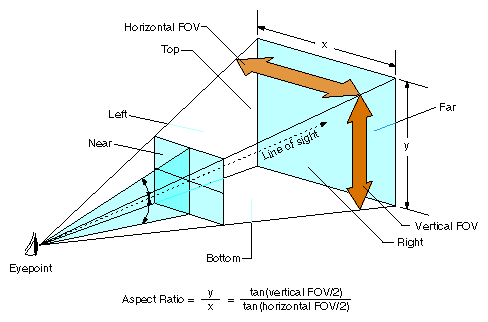
The viewing frustum is called symmetric when the vertical half-angles are equal and the horizontal half-angles are equal.
The FOV is the angular width of view. Use pfChanFOV(chan, horiz, vert) to set up viewing angles in IRIS Performer. The quantities horiz and vert are the total horizontal and vertical fields of view in degrees; usually you specify one and let IRIS Performer compute the other. If you're specifying one angle, pass any amount less than or equal to zero, or greater than or equal to 180, as the other angle. IRIS Performer automatically computes the unspecified FOV angle to fit the pfChannel viewport using the aspect-ratio preserving relationship
tan(vert/2) / tan(horiz/2) = aspect ratio
That is, the ratio of the tangents of the vertical and horizontal half-angles is equal to the aspect ratio. For example, if horiz is 45 degrees and the channel viewport is twice as wide as it is high (so the aspect ratio is 0.5), then the vertical field-of-view angle, vert, is computed to be 23.4018 degrees. If both angles are unspecified, pfChanFOV() assumes a default value of 45 degrees for horiz and computes the value of vert as described.
Clipping planes define the near and far boundaries of the viewing volume. These distances describe the extent of the visual range in the view, because geometry outside these boundaries is clipped, meaning that it isn't drawn.
Use pfChanNearFar(chan, near, far) to specify the distance along the line of sight from the viewpoint to the near and far planes that bound the viewing volume. These clipping planes are perpendicular to the line of sight. For the best visual acuity, choose these distances so that near is as far away as possible from the viewpoint and far is as close as possible to the viewpoint. Minimizing the range between near and far provides more resolution for distance comparisons and fog computations.
A viewpoint describes the position and orientation of the viewer. It is the origin of the viewing location, the direction of the line of sight from the viewer to the scene being viewed, and an up direction. The default viewpoint is at the origin (0, 0, 0) looking along the +Y axis, with +Z up and +X to the right.
Use pfChanView(chan, point, dir) to define the viewpoint for the pfChannel identified by chan. Specify the view origin for point in x, y, z world coordinates. Specify the view direction for dir in degrees by giving the degree measures of the three Euler angles: heading, pitch, and roll.
Heading is a rotation about the z axis, pitch is a rotation about the x axis, and roll is a rotation about the y axis. The value of dir is the product of the rotations ROTy(roll) * ROTx(pitch) * ROTz(heading), where ROTa(angle) is a rotation matrix about axis a of angle degrees.
Angles have not only a degree value, but also a sense, + or –, indicating whether the direction of rotation is clockwise or counterclockwise. Because different systems follow different conventions, it is very important to understand the sense of the Euler angles as they are defined by IRIS Performer. IRIS Performer follows the right-hand rule. According to the right-hand rule, counterclockwise rotations are positive. This means that a rotation about the x axis by +90 degrees shifts the +Y axis to the +Z axis, a rotation about the y axis by +90 degrees shifts the +Z axis to the +X axis, and a rotation about the z axis by +90 degrees shifts the +X axis to the +Y axis.
Figure 4-4 shows a toy plane (somewhat reminiscent of the Ryan S-T) at the origin of a coordinate system with the angles of rotation labeled for heading, pitch, and roll. The arrows show the direction of positive rotation for each angle.
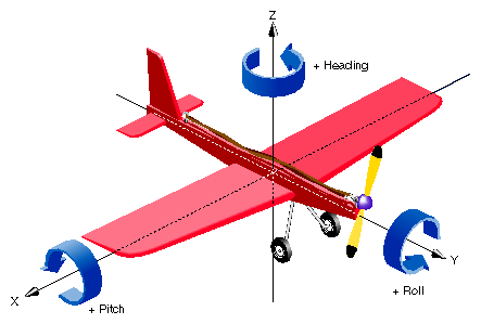
A roll motion tips the wings from side to side. A pitch motion tips the nose up or down. A yaw motion steers the plane, changing its heading. Accurate readings of these angles are critical information for a pilot during a flight, and a thorough understanding of how the angles function together is required for creation of an accurate flight simulation visual with IRIS Performer. The same is also true of marine and other vehicle simulations.
Alternatively, you can use pfChanViewMat(chan, mat) to create a 4x4 homogeneous matrix mat that defines the view coordinate system for channel chan. The upper left 3x3 submatrix defines the coordinate system axes, and the bottom row vector defines the origin of the coordinate system. The matrix must be orthonormal, or the results will be undefined. You can construct matrices using tools in the libpr library.
The origin and heading, pitch, and roll angles, or the view matrix, create a complete view specification. The view specification can locate the eyepoint frame-of-reference origin at any point in world coordinates. The gaze vector, the eye's +Y axis, can point in any direction. The up vector, the eye's +Z axis, can point in any direction perpendicular to the gaze vector.
You can query the system for the view and eyepoint-direction values with pfGetChanView(chan, point, dir), or obtain the view matrix directly with pfGetChanViewMat(chan, mat).
The view direction can be modified by one or more offsets, relative to the eyepoint frame-of-reference. View offsets are useful in situations where several channels render the same scene into adjacent displays for a wider field–of–view or higher resolution. Offsets are also used for multiple viewer perspectives, such as pilot and copilot views.
Use pfChanViewOffsets(chan, xyz, hpr) to specify additional translation and rotation offsets for the viewpoint and direction; xyz specifies a translation vector and hpr specifies a heading/pitch/roll rotation vector. Viewing offsets are automatically added each frame to the view direction specified by pfChanView() or pfChanViewMat().
For example, to create three different perspectives of the same scene as displayed by three windows in an airplane cockpit, use azimuth offsets of 45, 0, and -45 for left, middle, and right views. To create vertical view groups such as might be seen through the windscreen of a helicopter, use both azimuth and elevation offsets. Once the view offsets have been set up, you need only set the view once per frame. View offsets are applied after the eyepoint position and gaze direction have been established. As with the other angles, be aware that the conventions for measuring azimuth and elevation angles vary between graphics systems, so you should verify that the sense of the angles is correct.
Example 4-7 shows how to use various pfChannel-related functions. The code is derived from IRIS Performer sample programs.
main()
{
    pfInit();
    ...
    pfConfig();
    ...
    InitScene();
    InitPipe();
    InitChannel();

    /* Application main loop */
    while(!SimDone())
    {
        ...
    }
}

void InitChannel(void)
{
    pfChannel *chan;
    chan = pfNewChan(pfGetPipe(0));

    /* Set the callback routines for the pfChannel */
    pfChanTravFunc(chan, PFTRAV_CULL, CullFunc);
    pfChanTravFunc(chan, PFTRAV_DRAW, DrawFunc);

    /* Attach the visual database to the channel */
    pfChanScene(chan, ViewState->scene);

    /* Attach the EarthSky model to the channel */
    pfChanESky(chan, ViewState->eSky);

    /* Initialize the near and far clipping planes */
    pfChanNearFar(chan, ViewState->near, ViewState->far);

    /* Vertical FOV is matched to window aspect ratio. */
    pfChanFOV(chan, 45.0f/NumChans, -1.0f);

    /* Initialize the viewing position and direction */
    pfChanView(chan, ViewState->initView.xyz,
               ViewState->initView.hpr);
}

/* CULL PROCESS CALLBACK FOR CHANNEL*/
/* The cull function callback.  Any work that needs to be
 * done in the cull process should happen in this function.
 */
void
CullFunc(pfChannel * chan, void *data)
{
    static long first = 1;

    if (first)
    {
        if ((pfGetMultiprocess() & PFMP_FORK_CULL) &&
            (ViewState->procLock & PFMP_FORK_CULL))
                pfuLockDownCull(pfGetChanPipe(chan));
        first = 0;
    }
    PreCull(chan, data);

    pfCull();               /* Cull to the viewing frustum */

    PostCull(chan, data);
}

/* DRAW PROCESS CALLBACK FOR CHANNEL*/
/* The draw function callback. Any graphics functionality
 * outside IRIS Performer must be done here. I/O with pure  * IRIS GL devices must happen here.
 */
void
DrawFunc(pfChannel *chan, void *data)
{
    PreDraw(chan, data);     /* Clear the viewport, etc. */

    pfDraw();                /* Render the frame */

    /* draw HUD, read IRIS GL devices, or whatever else needs
     * to be done post-draw.
     */
    PostDraw(chan, data);
}
|
Each rendering pipeline can render multiple channels to multiple windows. Each channel represents an independent viewpoint into either a shared or an independent visual database. Different types of application can have vastly different pipeline-window-channel configurations. This section describes two basic extremes: visual simulation applications where there is typically one window per pipeline, and highly interactive uses that require dynamic window and channel configuration.
Often there will is a single channel associated with each pipeline, as shown in the top half of Figure 4-5. This section describes two important uses for multiple-channel support—multiple pipelines per system and multiple windows per pipeline—the second of which is illustrated in the bottom half of Figure 4-5.
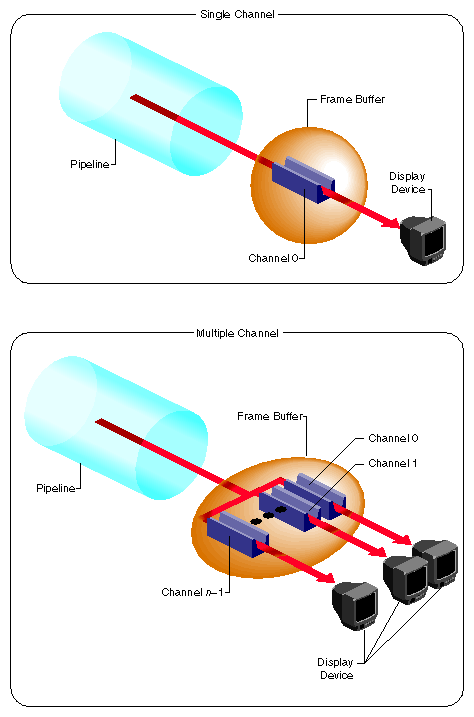
One situation that requires multiple channels occurs when inset views must appear within an image. A simple example of this application is a driving simulator in which the screen image represents the view out the windshield. If a rear-view mirror is to be drawn, it must overlay the main forward view to provide a separate view of the same database within the borders of the simulated mirror's frame.
Channels are physically rendered in the order that they are assigned to a pfPipeWindow on their parent pfPipe. Channels, upon creation, are assigned to the end of the channel list of the first window of their pfPipe. In the driving simulator example, creating pipes and channels with the following structure creates two channels on a single shared pipeline:
pipeline = pfGetPipe(0); frontView = pfNewChan(pipeline); rearView = pfNewChan(pipeline); |
In this case, IRIS Performer's actual drawing order becomes:
Clear frontView.
Draw frontView.
Clear rearView.
Draw rearView.
This default ordering results in the rear-view mirror image always overlaying the front-view image, as desired. You can control and re-order the drawing of channels within a pfPipeWindow with the pfInsertChan(pwin, where, chan) and pfMoveChan(pwin, where, chan) routines. More details about multiple channels and multiple window are discussed in the next section.
When the host has multiple Geometry Pipelines, as supported on Onyx RealityEngine2 systems, you can create a pfPipe and pfChannel pair for each hardware pipeline. The following code fragment illustrates a two-channel, two-pipeline configuration:
leftPipe = pfGetPipe(0); leftView = pfNewChan(leftPipe); rightPipe = pfGetPipe(1); rightView = pfNewChan(rightPipe); |
This configuration forms the basis for a high-performance stereo display system, since there is a hardware pipeline dedicated to each eye and rendering occurs in parallel.
The two-channel stereo-view application described in this example and the inset-view application described in the previous example can be combined to provide stereo views for a driving simulator with an inset rear-view mirror. The correct management of each eye's viewpoint and the mirror reflection helps provide a convincing sense of physical presence within the vehicle.
The third common multiple-channel situation involves support for multiple video outputs per pipeline. To do this, first associate each pipeline with a set of nonoverlapping channels, one for each desired view. Next, use one of the following video-splitting methods:
Use the Multi-Channel Option, available from Silicon Graphics for systems such as the Onyx RealityEngine2, where you can create up to six independent video outputs from a single Graphics Pipeline, with each video output corresponding to one of the tiled channels.
Connect multiple video monitors in series to a single pipeline's video output. Because each monitor receives the same display image, a masking bezel is used to obscure all but the relevant portion of each display surface.
The three multiple-channel concepts described here can be used in combination. For example, use of three RealityEngine2 pipelines, each equipped with the Multi-Channel Option, allows creation of up to 18 independent video displays. The channel-tiling method can also be used for some or all of these displays.
Example 4-8 shows how to use multiple channels on separate pipes.
Example 4-8. Multiple Channels, One Channel per Pipe
pfChannel *Chan[MAX_CHANS];

void InitChannel(int NumChans)
{
    /* Initialize each channel on a separate pipe */
    for (i=0; i< NumChans; i++)
        Chan[i] = pfNewChan(pfGetPipe(i));

    ...

    /* Make channel n/2 the master channel (can be any
     * channel).
     */
    ViewState->masterChan = Chan[NumChans/2];

    {
        long share;

        /* Get the default channel-sharing mask */
        share = pfGetChanShare(ViewState->masterChan);

        /* Add in the viewport share bit */
        share |= PFCHAN_VIEWPORT;

        if (GangDraw)
        {
            /* add GangDraw to channel share mask */
            share |= PFCHAN_SWAPBUFFERS_HW;
        }
        pfChanShare(ViewState->masterChan, share);
    }

    /* Attach channels */
    for (i=0; i< NumChans; i++)
        if (Chan[i] != ViewState->masterChan)
            pfAttachChan(ViewState->masterChan, Chan[i]);

    ...
    /* Continue with channel initialization */
}
|
For some interactive applications, you may want to be able to dynamically control the configuration of Channels and Windows. IRIS Performer allows you to dynamically create, open, and close windows, as described in the previous section, “pfPipeWindows in Action“. You can also move channels amongst the windows of the shared parent pfPipe, and re-order channels within a pfPipeWindow. Channels can be appended to the end of a pfPipeWindow channel list with pfAddChan() and removed with pfRemoveChan(). A channel can only be attached to one pfPipeWindow — no instancing of pfChannels is allowed. When a pfChannel is put on a pfPipeWindow, it is automatically deleted from its previous pfPipeWindow. A channel that is not assigned to a pfPipeWindow is not drawn (though it may still be culled).
You can control and re-order the drawing of channels within a pfPipeWindow with the pfInsertChan(pwin, where, chan) and pfMoveChan(pwin, where, chan) routines. Both of these routines do a type of insertion: pfInsertChan() will add chan to pwin's channel list in front of the channel in the list at location where. pfMoveChan() will delete chan from it's old location and move it to where in pwin's channel list.
In many multiple-channel situations, including the examples described in the previous section, it is useful for channels to share certain attributes. For the three-channel cockpit scenario, each pfChannel shares the same eyepoint while the left and right views are offset using pfChanViewOffsets(). IRIS Performer supports the notion of channel groups, which facilitate attribute sharing between channels.
pfChannels can be gathered into channel groups that share like attributes. A channel group is created by attaching one pfChannel to another, or to an existing channel group. Use pfAttachChan() to create a channel group from two channels or to add a channel to an existing channel group. Use pfDetachChan() to remove a pfChannel from a channel group.
A channel share mask defines shared attributes for a channel group. The attribute tokens listed in Table 4-3 are bitwise OR-ed to create the share mask.
Table 4-3. Attributes in the Share Mask of a Channel Group
Token | Shared Attributes |
|---|---|
Horizontal and vertical fields of view | |
View position and orientation | |
(x, y, z) and (heading, pitch, roll) offsets of the view direction | |
Near and far clipping planes | |
All channels display the same scene | |
All channels display the same earth/sky model | |
All channels use the same stress filter | |
All channels use the same LOD modifiers | |
All channels swap buffers at the same time |
Use pfChanShare() to set the share mask for a channel group. By default, channels share all attributes except PFCHAN_VIEW_OFFSETS. When you add a pfChannel to a channel group, it inherits the share mask of that group.
A change to any shared attribute is applied to all channels in a group. For example, if you change the viewpoint of a pfChannel that shares PFCHAN_VIEW with its group, all other pfChannels in the group will acquire the same viewpoint.
Two attributes are particularly important to share in adjacent-display multiple-channel simulations: PFCHAN_SWAPBUFFERS and PFCHAN_LOD. PFCHAN_LOD ensures that geometry that straddles displays is drawn the same way in each channel. In this case, all channels will use the same LOD modifier when rendering their scenes so that LOD behavior is consistent across channels. PFCHAN_SWAPBUFFERS ensures that channels refresh the display with a new frame at the same time. pfChannels in different pfPipes that share PFCHAN_SWAPBUFFERS will frame-lock the pipelines together.
Example 4-9 illustrates the use of multiple channels and channel-sharing.
pfChannel *Chan[MAX_CHANS];

main()
{
    pfInit();
    ...
    /* Set number of pfPipes desired.  THIS MUST BE DONE
     * BEFORE CALLING pfConfig().
     */
    pfMultipipe(NumPipes);
    ...
    pfConfig();
    ...
    InitScene();

    InitChannels();

     pfFrame();

    /* Application main loop */
    while(!SimDone())
    {
        ...
    }
}

void InitChannel(int NumChans)
{
    /* Initialize all channels on pipe 0 */
    for (i=0; i< NumChans; i++)
        Chan[i] = pfNewChan(pfGetPipe(0));

    ...

    /* Make channel n/2 the master channel (can be any
     * channel).
     */
    ViewState->masterChan = Chan[NumChans/2];

    ...

    /* Attach all Channels as slaves to the master channel */
    for (i=0; i< NumChans; i++)
        if (Chan[i] != ViewState->masterChan)
            pfAttachChan(ViewState->masterChan, Chan[i]);

    pfSetVec3(xyz, 0.0f, 0.0f, 0.0f);
    /* Set each channel's viewing offset. In this case use
     * many channels to create one multichannel contiguous
     * frustum with a 45˚ field of fiew.
     */
    for (i=0; i < NumChans; i++)
    {
        float fov = 45.0f/NumChans;

        pfSetVec3(hpr, (((NumChans - 1) * 0.5f) - i) * fov,
                  0.0f, 0.0f);
        pfChanViewOffsets(Chan[i], xyz, hpr);
    }

    ...

    /* Now, just configure the master channel and all of the
     * other channels will share those attributes.
     */

    chan = ViewState->masterChan;
    pfChanTravFunc(chan, PFTRAV_CULL, CullFunc);
    pfChanTravFunc(chan, PFTRAV_DRAW, DrawFunc);
    pfChanScene(chan, ViewState->scene);
    pfChanESky(chan, ViewState->eSky);
    pfChanNearFar(chan, ViewState->near, ViewState->far);
    pfChanFOV(chan, 45.0f/NumChans, -1.0f);
    pfChanView(chan, ViewState->initView.xyz,
               ViewState->initView.hpr);
    ...
}
|