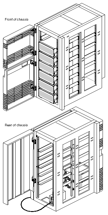
This chapter describes the product controls and connectors on the SCSIBox 2 and Vault.
Figures 4-1 through 4-4 and the following sections describe the major components of the SCSIBox 2.
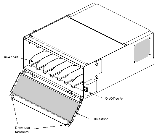
The front of the SCSIBox 2 chassis has these major components (see Figure 4-1):
| Drive door | opens and closes using two quarter-turn wing-nut fasteners near the top corners of the box. To open and close the door, push in on the fastener and turn partway. Do not overturn the fasteners, they can snap off and break.
| |||
| On/Off switch | controls power to all drives. This green switch illuminates when turned on. | |||
| Drive shelves | house the SCSI drives and drive sled. The shelves are removable to accommodate full-height drives. See Section 5.3.5, "Removing a Drive Shelf to Install a Full-Height Drive."
|
 | Caution: Do not overturn the quarter-turn door fasteners or else they may break. |
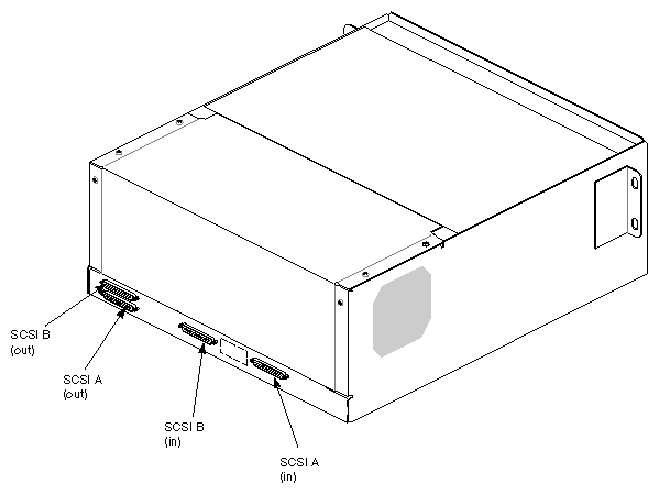
These major components are located on the back of the SCSIBox 2 (see Figure 4-2):
| SCSI In (A/B) | provides a 68-pin SCSI-2 differential connector.
| |||
| SCSI Out (A/B) |
|
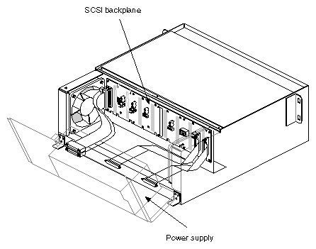
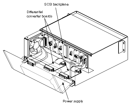
These parts are located inside the SCSIBox 2 (see Figures 4-3 and 4-4):
| Power supply | provides 5 and 12 volts of power to all drives and fans in the box, respectively. | |||
| Differential converter boards |
| |||
| SCSI backplane |
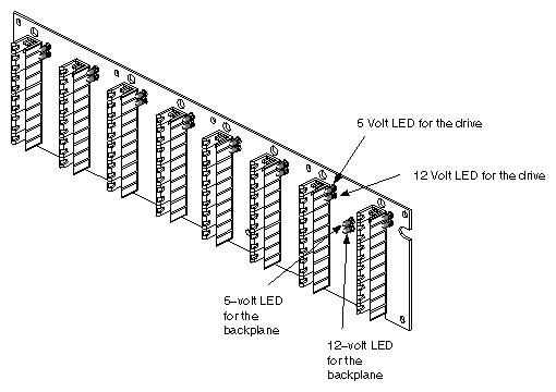
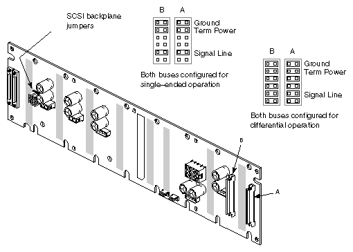
Figure 4-5 shows the front view of the SCSI backplane. Note the pair of green LEDs associated with each drive bay. When illuminated, the top LED signifies that the drive is receiving 5 volts, and the lower LED signifies that the drive is receiving 12 volts. Figure 4-6 shows the rear view of the SCSI backplane and the required jumper settings. |
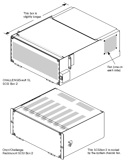
As stated in Chapter 1, "General Information," the Vault SCSIBox 2 and the Onyx and CHALLENGE rackmount SCSIBox 2 (also known as the stubbi-SCSI box) are two different SCSI boxes and are not interchangeable. The Vault SCSIBox 2 can install only into a Vault peripherals rack and the other SCSIBox 2 can install only into an Onyx and CHALLENGE rackmount system. The differences between these two drive boxes are: (see also Figure 4-7).
The Vault SCSIBox 2 has a self-contained power supply that directly converts the
220 VAC input to 5 and 12 VDC. The other SCSIBox 2 contains a 512S power board that converts the 48 VDC from the off-line switching (OLS) power supply in the Onyx and CHALLENGE rackmount system to the required voltages.The Vault SCSIBox 2 has two internal fans; the other SCSIBox 2 is cooled by two large, central fans in the Onyx and CHALLENGE rackmount chassis.
The Vault SCSIBox 2 is a slighter longer box.
 | Note: Other than these differences, the Vault SCSIBox 2 and the Onyx and CHALLENGE SCSIBox 2 are essentially the same. Drives are directly interchangeable between the two boxes. No drive sled or drive shelf modification is required. |
The SCSIBox 2 is available in three configurations:
single-ended
differential
RAID
Note: For information on RAID installation, see the Raid Hardware Installation and Upgrade Instructions (P/N 108-0104-xxx) as required.
The single-ended configuration enables you to use single-ended devices in the rack. This box contains two differential converter boards.
| Caution: The total cable length from the IO4 board to the last device in this configuration cannot exceed 81 feet (25 meters). |
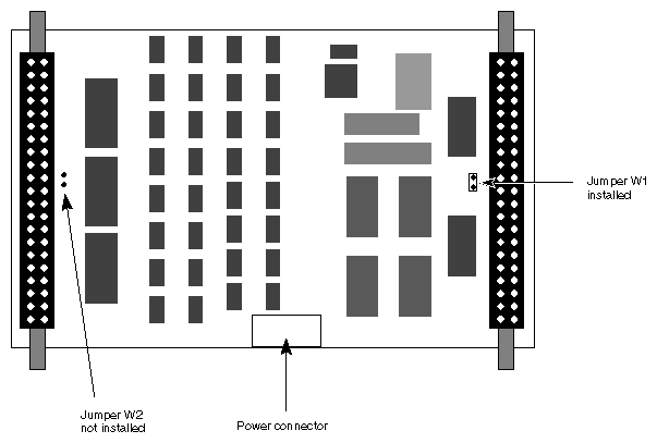
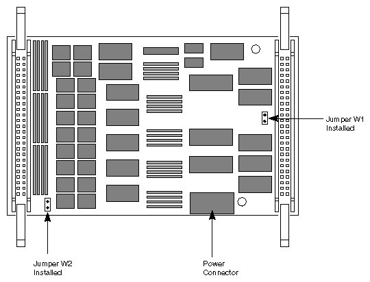
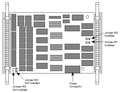
The single-ended SCSIBox 2 uses three versions of the converter board. Two are manufactured by Rancho and the third board is produced by NCR. If you are replacing a converter board in the SCSI box, ensure that the replacement board is jumpered according to Figure 4-8 through Figure 4-10.
Unlike previous peripheral racks such as the POWER Store™ (Tallboy/Julius), the Vault contains preinstalled drive rails for easier installation in the field. Figure 4-11 shows the front of rear view of the Vault.