This chapter covers the following procedures:
installing a SCSIBox 2
installing devices into the drive box
connecting the Vault to the host system
connecting multiple Vaults
Perform the following before you actually begin the installation:
Check the number of available differential SCSI ports on the host system. Do you have the sufficient number of channels to support the rack configuration?

Note: Each drive box requires at least one dedicated channel and two channels for disk striping. Ensure that you are using only differential SCSI channels on the I/O panel.
Check that you have the required cabling. Do you have enough external SCSI cables (P/N 9290053) to handle your configuration? Are you planning to daisy-chain between boxes? If so, do you have enough 2-ft cables (P/N 9290055)?
Note: There are also a few rules to follow when daisy-chaining between drive boxes. See 5.5.2, "Daisy-chaining between SCSIBox 2s," for more information.
This section describes how to install a single-ended or differential SCSIBox 2 into a Vault.
 | Caution: Do not attempt to install a SCSI Box 1 into a 12-drive box Vault (front- and back-loading chassis). The SCSI Box 1 is too long and will not fit properly into a 12-drive box Vault as they will bump against the boxes on the other side of the chassis. In addition, do not install a 1/2-inch tape drive into a Vault rack. This will violate the UL, TUV, and CSA agency approval rating of the Vault rack. |
The following installation procedure applies to only the Challenge Vault SCSIBox 2 and not the SCSIBox2 that installs into a Challenge or an Onyx rackmount system. See Section 4.1.4, "Comparing SCSIBox 2s," for more information.
These instructions apply to both the single-ended and differential SCSIBox 2.
| Caution: The SCSIBox 2 weighs 35 lb (16 kg) without drives. For easier loading, it is recommended that the drives be inserted after the box is installed. |
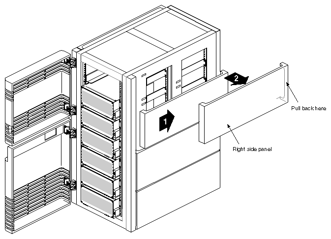
Remove the side panels on both sides of the chassis by tugging hard on the panel (towards the rear) and pulling them straight out and away. See Figure 5-1. This allows you to gain better access for cabling.
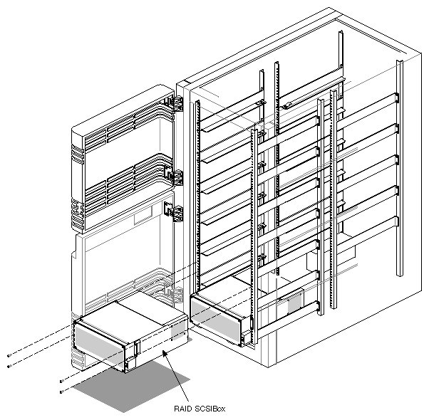
Note: You can remove the panels just about anytime during the procedure, but it's recommended that you do it at the beginning to ease installation. Lift up the first SCSIBox 2 and install it into the rails at the bottom. Always start with the lowest set of rails, then work your way up. See Figure 5-2.
Caution: If you install the drive boxes in only the top portion of the Vault, the rack can tip over or the drive boxes can fall out when you try to remove them. See Figure 5-3. Note: The SCSIBox 2 is held in place by four screws and gravity. There is no additional holding mechanism to keep the boxes from falling after they have been pulled away from the rack. Secure the SCSIBox 2 to the vertical rails on the chassis using two screws on each side. Refer to Figure 5-2.
Use filler plates as required to cover open areas on the chassis.
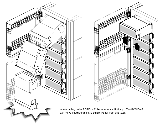
| Caution: The Vault chassis does not have special support mechanisms to hold the SCSIBox 2 in place while the drive box is pulled out from the chassis. The top two SCSIBox 2s, especially, can easily fall to the ground and cause equipment damage or bodily injury, if they are pulled too far out and left sitting on the rails. |
This section describes how to install and remove drives for the SCSIBox 2; however, before you install drives into the SCSIBox 2, you need to perform these tasks:
select the SCSI ID for the drives
select the correct channel (A or B) on the drive sled
ensure that the drive sled jumpers are set correctly
| Note: A set of jumpers is also located on the SCSI backplane of the SCSIBox 2; however, these jumpers should already be properly set at the factory. See Chapter 4, "Chassis Tour," for more information. |
Jumper the SCSI ID for each drive to avoid addressing conflicts. For complete drive jumpering information, refer to the Peripherals Guide.
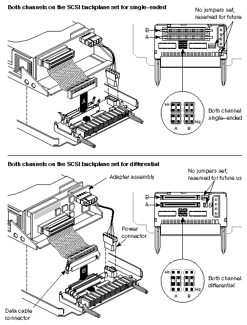
Determine which channel (A or B) you want the drive to occupy, then plug the SCSI cable from the drive into the proper channel connector. See Figure 5-4.
Depending on the SCSIBox 2 type, the drive sled board jumpers should be set for either single-ended or differential operation. See Figure 5-4 for the jumper configurations.
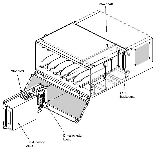
The SCSIBox 2 uses front-loading drives mounted on drive sleds for easy installation and removal. To install or remove a drive, follow these instructions and see Figure 5-5.
Hold the drive sideways, with the top of the drive facing right and the bottom of the drive sled facing left.
Install the drive module into the drive shelf and slide the module all the way into place, then push the drive lever down. The drive module should click into place, flush with the slot, and should not come out when you pull it.
Close and screw in (one quarter-turn) the SCSI box door after you install all of the drives. Be careful not to over tighten the fastener; it could break off.
Caution: The front door must be closed during operation to comply with FCC regulations. To remove the drive, push the drive lever up and then slide the module out.
Caution: The SCSIBox 2 does not have a set of safety rails to hold it in place. If you have drives installed, do not pull the drive box too far out on the rails. The drive box and drives may fall to the ground and become damaged. See Figure 5-3. Note: The SCSI box can safely be pulled out a short distance (about 5 to 6 inches or 13 to 15 cm) on the rails without direct support.
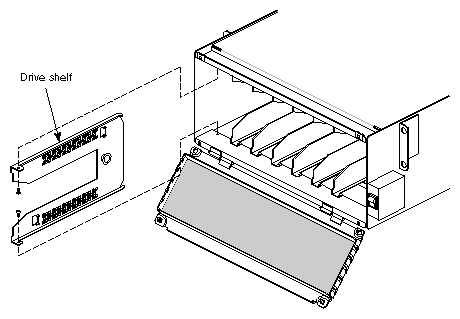
Full-height drives require two half-height drive slots. To accommodate the greater size of the full-height drive, you must remove a drive shelf from the SCSIBox 2 by following these instructions:
Open the front door of the SCSIBox 2.
Select a drive shelf, then remove the two Phillips screws (No. 0 or 1) that secure the drive shelf to the top and bottom of the SCSIBox 2 chassis (see Figure 5-6).
Pull the drive shelf out of the chassis and store it for later possible use.
The physical differences between single-ended and differential SCSI devices may sometimes be obscure. Other than by the drive part number and description, there is no sure-fire way to always tell the difference between single-ended and differential devices.
Fortunately, most Silicon Graphics single-ended drives currently have the 50-pin, 8-bit, narrow SCSI connector, and all differential drives, such as the 3-1/2 inch IBM 2 GB hard disk, use the 68-pin, 16-bit, wide SCSI connector; however, this will not always be the case.
Future single-ended devices will also use the 68-pin, wide SCSI connector. So, while all 50-pin SCSI connectors will invariably be single-ended devices, not all 68-pin connectors will be differential devices.
| Note: The only major difference between a 68-pin single-ended SCSI drive and a 68-pin differential drive is that the differential drive has a differential converter board and the single-ended drive does not. |
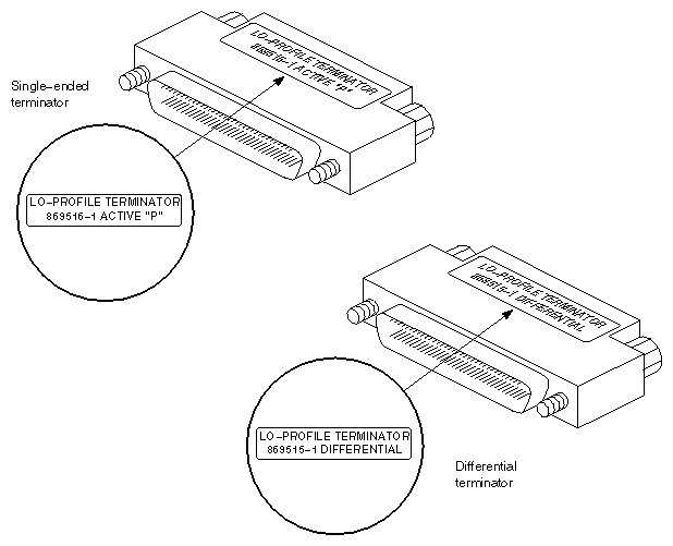
SCSI terminators must be matched to the protocol of the SCSI channel. There are two different terminators: one for single-ended protocol and one for differential protocol.
These terminators are visually identical, except for the manufacturing part numbers. See Table 5-1 and Figure 5-7.
Table 5-1. Identifying SCSI Channel Terminators
Component | SGI Part Number | Distinguishing Marks |
|---|---|---|
Single-ended terminator | 9660008 | AMP 869516-1 ACTIVE "P" |
Differential terminator | 9660006 | AMP 869515-1 DIFFERENTIAL |
| Caution: Never use a single-ended SCSI terminator on a differential channel. Connecting a single-ended terminator to a differential channel shorts power to ground. |
This section describes the following cabling:
connecting the SCSI cables from the Vault to the host system
daisy-chaining between SCSIBox 2s
| Caution: Make sure that the system power is turned off before beginning these steps. |
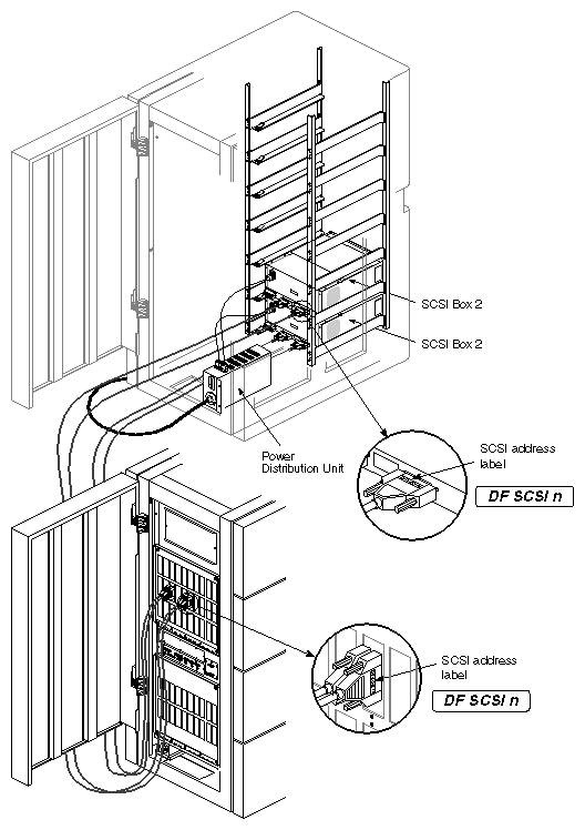
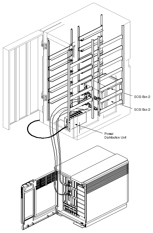
Follow these instructions and see Figure 5-8 to cable the rack to the host system.
| Note: The SCSIBox 2 has two SCSI channels (A and B) to help provide disk striping throughput capability. |
Open the back door of the Vault.
Find the SCSI A or B connector on the SCSIBox 2.
Note: You should have already selected an A or B channel for each drive in the SCSIBox 2 before getting to this stage. See Section 5.3, "Installing and Removing SCSIBox 2 Drives," for more information. Attach one end of the external 68-pin SCSI cable to the A or B connector.
Note: If you are cabling between the host and the drive box, use the 68-pin 50-foot cable (P/N 9290053). If you are cabling between drive boxes, use the 2-foot cable (P/N 9290055). For more information on daisy-chaining, see Section 5.5.2, "Daisy-Chaining Between SCSIBox 2s." After installation, make sure you properly label all the drives and SCSI cables. See Section 5.7, "Labels on a SCSI Channel," for more information.
Note: On SCSI cables, use matching labels on each end of the connector to help identify these cables. An extra set of SCSI labels (P/N 024-0640-001) are provided for this purpose. Open the front door of the deskside host system or rear door of the rackmount host system to access the I/O door. Attach the other end of the SCSI cable to a SCSI port on the I/O panel and also be sure to place a label on the SCSI connector for identification.
Note: The SCSIBox 2 in the Vault requires a differential SCSI connection. Ensure that the SCSI channel is set for differential operation. Connect a terminator into the unused SCSI port on the SCSIBox 2.
Note: If you are connecting boxes to both sides of the Vault rack, be sure to complete the cabling on one side of the rack before you begin SCSIBox 2 installation on the other side of the rack. Use the openings on the side of the rack (created after you have removed the side panels) to cable the other side of the rack.
| Note: If you have RAID drives, see the Raid Hardware Installation and Upgrade Instructions (P/N 108-0104-xxx) for installation information as required. |
Here is a list of do's and don'ts regarding SCSIBox 2 daisy-chaining:
You cannot daisy-chain between racks.
You cannot daisy-chain more than 15 drives on one channel.
You can daisy-chain between SCSIBox 2s, but only if all of the drives in the SCSIBox 2s are 2.0 GB disks.
Follow these instructions to daisy-chain between drive boxes:
Use a 2-foot cable (P/N 9290055) to cable between the SCSIBox 2s.
Plug one end into an A or B channel on one SCSIBox 2. Plug the other end into the same channel on the other SCSIBox 2.
Plug a terminator into each unused A or B channel on the SCSIBox 2s.
The host system can support up to two Vault racks. This section describes how to connect two racks to the host.
| Caution: Each rack requires a direct connection to a SCSI channel on an IO4 or mezzanine board. You cannot daisy-chain drive boxes between Vault racks. |
Follow these procedures to connect two racks to the system:
Open the back door of the Vault.
Find the SCSI A or B connector on the SCSIBox 2.
Attach one end of the external 68-pin SCSI cable to this connector.
Access the I/O panel of the host system.
Attach the other end of the SCSI cable to a SCSI port on the I/O panel.
Connect a terminator into the unused SCSI port on the SCSIBox 2.
To simplify SCSI channel identification, labels are on the I/O panel SCSI connectors, cables, SCSI devices, SCSI boxes, and terminators. Depending on the component in question, a label may provide:
a channel number to identify the I/O board that provides the SCSI signal
a channel protocol to identify whether the channel is single-ended or differential
a bus number to identify the bus inside a SCSI box that supplies the SCSI channel, either A or B
This section describes the SCSI channel labels for individuals who need to determine the configuration of a SCSI channel or modify the SCSI labels for a deskside, rackmount, or Vault chassis.
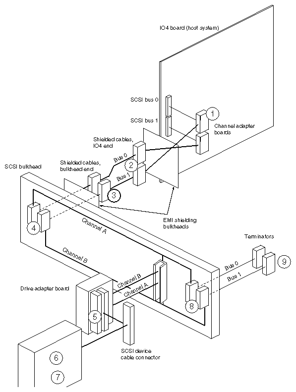
To determine the protocol of a SCSI channel with missing or unreadable labels, check the configuration of one or more components on the channel using the information in the system's installation instructions. The easiest component to reach is the drive adapter board. Also, channel adapter boards are color-coded to simplify identification. Single-ended channel adapter boards are green, and differential channel adapter boards are red. See Table 5-2 through Table 5-11 and Figure 5-9 through Figure 5-24 for additional information.
| Note: The "key" number listed in the left column of Table 5-2 through Table 5-11, references callout numbers shown in Figure 5-21. |
Table 5-2. Channel Adapter Board Label
Key | Description | Procedure |
|---|---|---|
1 | Identifies SCSI protocol (SE or DF) and the bus number (0-7); SE SCSI 0 label is part number 024-0637-xxx; DF SCSI 1 label is part number 024-0640-xxx (see Figure 5-22). Secondary SCSI boxes are labeled from label set part numbers 024-0610-xxx through 024-0654-xxx. | Select label based on the slot and bus number of the I/O board. For example, bus 0 on an IO4 board in slot 13 gets the label DF SCSI 130. Place label on the flat face of the cable connector, aligning the bottom of the text along the outer long edge of the connector. |
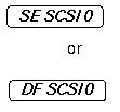
Table 5-3. SCSI Cable Label, Board End
Key | Description | Procedure |
|---|---|---|
2 | Identifies SCSI protocol (SE or DF) and the bus number (0-7); SE SCSI 0 label is part number 024-0637-xxx; DF SCSI 1 label is part number 024-0640-xxx (see Figure 5-23.) Secondary SCSI boxes are labeled from label set part numbers 024-0610-xxx through 024-0654-xxx. | Select label based on the slot and bus number of the I/O board. For example, bus 0 on an IO4 board in slot 13 gets the label DF SCSI 130. Place label on the flat face of the cable connector, aligning the bottom of the text along the inner long edge of the connector. |
Table 5-4. SCSI Cable Label, Bulkhead End
Key | Description | Procedure |
|---|---|---|
3 | Identifies SCSI protocol (SE or DF) and the bus number (0-7); SE SCSI 0 label is part number 024-0637-xxx; DF SCSI 1 label is part number 024-0640-xxx (see Figure 5-24). Secondary SCSI boxes are labeled from label set part numbers 024-0610-xxx through 024-0654-xxx. | Select label based on the slot and bus number of the I/O board. For example, bus 0 on an IO4 board in slot 13 gets the label DF SCSI 130. Place label on the flat face of the cable connector, aligning the bottom of the text along the inner long edge of the connector. |
Table 5-5. Bulkhead SCSI Cable Connector Markings
Key | Description | Procedure |
|---|---|---|
4 | In early revisions, no markings for channel connectors A and B; channel A is the bottom connector, and channel B is the top connector; in later revisions, the markings JIA_SCSI and JIB_SCSI are on the bulkhead next to the connectors. See Figure 5-25. | None required. |
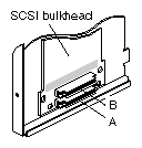
Table 5-6. Drive Adapter Board Markings for SCSI Channels A and B
Key | Description | Procedure |
|---|---|---|
5 | On 50-pin adapter boards (see Figure 5-26), the two selectable connectors are marked JA1 and JB1; on 68-pin adapters, the connectors are marked J1_A and J1_B. | None required. |
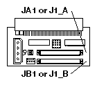
Table 5-7. SCSI Device Label for Devices with Large Front Bezels
Key | Description | Procedure |
|---|---|---|
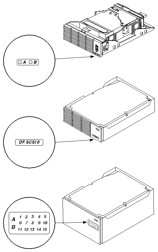
6a | Identifies the SCSI channel (A or B) and the device ID number (1-15), part number 024-0632-xxx. See Figure 5-27. | Place label on the inner face of the drive door, along the hinged edge of the door and as close as possible to the corresponding drive. |
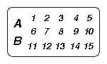
Table 5-8. SCSI Device Label for Devices with Restricted Space on the Front Bezel
Key | Description | Procedure |
|---|---|---|
6b | Identifies the SCSI protocol (SE or DF) and bus number (0-7): SE SCSI 0 label is part number 024-0637-xxx; DF SCSI 1 label is part number 024-0640-xxx (see Figure 5-28). Secondary SCSI boxes are labeled from label set part numbers 024-0610-xxx (shown) through 024-0654-xxx. | Select label based on the slot and bus number of the I/O board. For example, bus 0 on an IO4 board in slot 13 gets the label DF SCSI 130. Place label on the flat face of the cable connector, aligning the bottom of the text along the inner long edge of the connector. |
Table 5-9. SCSI Device Label for Devices with Minimal Space on the Front Bezel
Key | Description | Procedure |
|---|---|---|
6c | Identifies the SCSI channel (A or B), part number 024-0671-xxx. See Figure 5-29. | Place label directly on the face of the drive, ensuring that it does not block any airflow. Indicate whether the device is configured for channel A or B. |

Table 5-10. SCSI Box Base Label
Key | Description | Procedure |
|---|---|---|
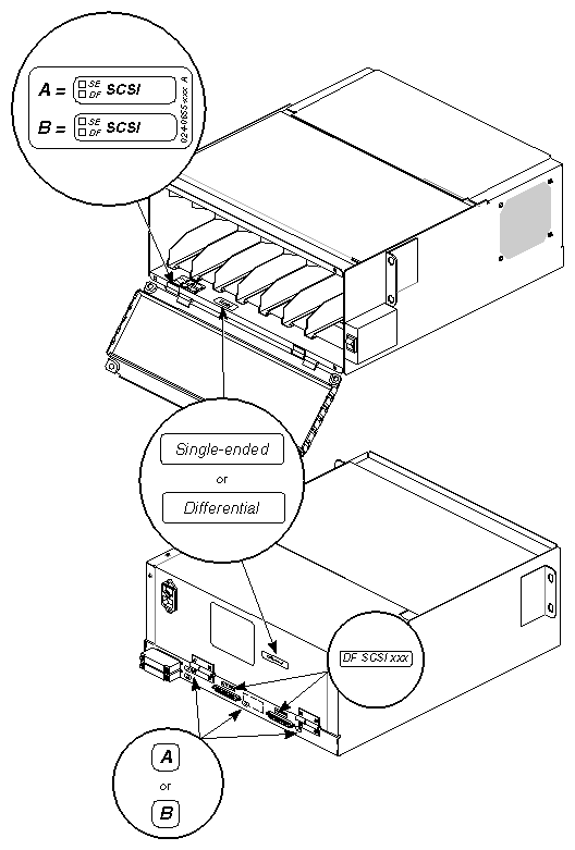
7a | SCSI box label, part number 024-0655-xxx. See Figure 5-30. | Place label on the inner face of the drive door in the upper left corner. For each channel, indicate the channel protocol (SE for single-ended, DF for differential) and the SCSI bus number (0 or 1). |
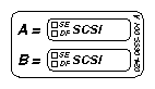
Table 5-11. SCSI Box Cover Label
Key | Description | Procedure |
|---|---|---|
7b | Identifies SCSI protocol (SE or DF) and bus number (0-7). See Figure 5-31. SE SCSI 0 label is part number 024-0637-xxx; DF SCSI 1 label is part number 024-0640-xxx. Secondary SCSI boxes are labeled from label set part number s 024-0610-xxx (shown) through 024-0654-xxx. | Select label based on the slot and bus number of the I/O board. For example, bus 0 on an IO4 board in slot 13 gets the label DF SCSI 130. Place label on the flat face of the cable connector, aligning the bottom of the text along the inner long edge of the connector. |
Table 5-12. Bulkhead Terminator Connector Markings
Key | Description | Procedure |
|---|---|---|
8 | SCSI bulkhead (see Figure 5-32). In early revisions, no distinction between connectors A and B; channel A is the bottom connector, and channel B is the top connector; in later revisions, the markings JTA_SCSI and JTB_SCSI are on the bulkhead next to the connectors. | None required. |
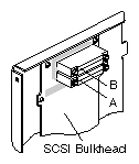
Table 5-13. SCSI Terminator Connector Label
Key | Description | Procedure |
|---|---|---|
9 | Identifies SCSI protocol (SE or DF) and bus number (0-7). See Figure 5-33. SE SCSI 0 label is part number 024-0637-xxx; DF SCSI 1 label is part number 024-0640-xxx. | Select label based on the slot and bus number of the I/O board. For example, bus 0 on an IO4 board in slot 13 gets the label DF SCSI 130. Place label on the flat face of the cable connector, aligning the bottom of the text along the inner long edge of the connector. |