This chapter discusses important connectors, jumpers, and status indicators on the FDDIXPress board. For additional discussion on the FDDIXPress board hardware, refer to Chapter 4, "Principles of Operation."
Table 1-1 describes the most important connectors on the board. Figure 1-1 shows their locations.
Table 1-1. Connector Descriptions
Connector Name | Function |
|---|---|
P1 and P2 | Provides interface to the VMEbus. |
A | Provides connection to fiber optic cable A. (For a dual-attached station, the cable consists of the primary ring input and secondary ring output.) |
B | Provides connection to fiber optic cable B. (For a dual-attached station, the cable consists of primary ring output and secondary ring input.) |
J3 (not used) | Serves as input connector to second FDDI controller board in dual MAC configuration. |
J4 (not used) | Serves as output connector to second FDDI controller board in dual MAC configuration. |
J7 | Provides control line to optical bypass switch (OBS). |
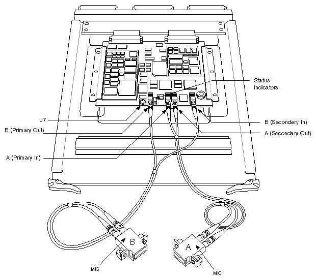
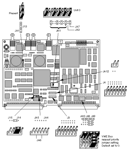
Table 1-2 summarizes the jumper blocks on the FDDIXPress motherboard. Figure 1-2 illustrates the jumper block locations and default settings.
Table 1-2. Jumpers on Main Board
Jumper | Default Setting | Instruction | Description |
|---|---|---|---|
JA1 | Jumper | Do not alter default. | No jumper = single PHY. |
JA2 | Not applicable | Not used. | Not interpreted. |
JA3 | No jumper | Do not alter default. | No jumper = single-MAC. |
JA4 | No jumper | Do not alter default. | No jumper = single-MAC. |
JA5 | No jumper | Do not alter default. | No jumper = host control of OBS. |
JA6 | No jumper | Do not alter default. | No jumper = host control of OBS. |
JA7 | Jumper | Do not alter default. | No jumper = early release (release at start of
last BBSY cycle). |
JA8 to JA10 | Level 0 | Alteration optional. | Sets VMEbus request priority level. Can be set to 0 (lowest), 1, 2, or 3. See Figure 1-4 for details. |
JA11 | Unit 0 | Must be changed when multiple boards are installed in one system. | Sets unit number for the board. Can be set to 0, 1, 2, or 3. See Figure 1-3 for details. Each FDDIXPress board in a system must have a unique unit number. |
JA12 | No jumper | Do not alter default. | Must not be jumpered. |
J13 | Jumper (pins 2 to 3) | Do not alter default. | When jumper is installed on pins 1-2,
interrupt is generated when a frame is
missed. |
J14 | Jumper (pins 2 to 3) | Do not alter default. | When jumper is installed on pins 1-2,
enables frame segmentation into 2 KB
segments. |
J15 | No jumper | Do not alter default. | No jumper = no interrupt when restricted
token is received. |
Note: Connectors J3 and J4 are not used. See Table 1-1 for more information. |
|
|
|
Jumper block JA11 sets the unit number for the board. Each FDDIXPress board in a system must have a unique number; two or more FDDIXPress boards with the same unit number will cause the system to function in an unpredictable manner. When a single FDDIXPress board is installed in a system, the default setting for unit 0 should be used. When two or more FDDIXPress boards are installed in a system, set the JA11 jumper on each board (as illustrated in Figure 1-3) so that the unit number is unique.
Up to four FDDIXPress boards can be used in each Challenge, Onyx, IRIS Crimson, Professional, or POWER Series workstation or server. The FDDIXPress boards in a system (unit 0, unit 1, unit 2, unit 3, as set by jumper block JA11) are controlled by drivers with similarly numbered interface names (ipg0, ipg1, ipg2, and ipg3). All FDDIXPress boards shipped from Silicon Graphics are configured as unit 0.
 | Note: See Section 1.4, "VMEbus Arbitration," regarding the arbitration scheme for single or multiple FDDIXPress board configurations. |
| Note: The request priority default setting of "0" applies to all Silicon Graphics systems with a VME bus such as the Challenge, Onyx, and POWER Series systems. See also Section 1.4, "VMEbus Arbitration," for bus arbitration information. |
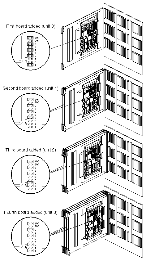
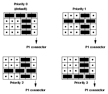
Table 1-3 describes the status indicators. Refer to Figure 1-1 for the locations of the LED status indicators.
Table 1-3. LED Status Indicators
LED Color | Status |
|---|---|
Red is on; green is off. | FDDI ring is down. |
Green is on; red is off. | FDDI board is operating, but network is quiet. |
Both red and green are on. | FDDI ring is up and the board is active. |
The VME bus has four bus request levels (BR3 through BR0) and supports three arbitration schemes.
| prioritized | If more than one bus request is in the queue, the arbitration logic automatically grants bus access to the highest-level request first. | |
| round-robin | If no priority request is present, the arbitration logic grants bus access on a daisy-chained basis, with VME boards closest to the left side of the card cage (as you face the system) receiving access first. For example, if a VME board resides in slot 5 and another resides in slot 8, the VME board in slot 5 receives bus access before the board in slot 8. Slot 5 is closer the left side of the card cage. | |
| single level | If all the requests are at the same level (BR3 through BR0), the requests are daisy-chained. |
In addition, the VME subsystem adheres to the following criteria:
VME bus request level 3 is always higher priority than 0, 1, and 2.
VME bus request levels 0, 1, and 2 are round robin.