The FDDIXPress™ is a network connection product (adapter board and software) that provides high-speed fiber distributed data interface (FDDI) network connections. This manual provides instructions for installing the FDDIXPress board into a VMEbus™ option slot on the following Silicon Graphics® platforms:
POWER Series™
Professional Series
IRIS Crimson™
Onyx™ (deskside and rackmount)
CHALLENGE L™ (also referred to as Challenge deskside)
CHALLENGE XL™ (also referred to as Challenge rackmount)
The FDDIXPress board processes the transmission and reception of data packets (frames) across a 100-megabit-per-second FDDI network and maintains communication by wrapping in the event of a break in the ring (as illustrated in Figure In-1 and Figure In-2). The board is a single media access control (MAC) dual-attachment FDDI board; it can be connected as a dual-attachment station to the dual ring, as a single-attachment station to a concentrator, or as a dual-homed station, where both ports are attached to concentrators and one connection acts as a backup.
The FDDIXPress board for the above-listed platforms is a single-slot 6U board that resides in a 9U adapter board. The FDDIXPress is a VMEbus-compatible board that is based on a subset of the AMD SUPERNET™ LSI chips.
For a detailed description on the board, refer to Chapter 4, "Principles of Operation."
There are a number of different FDDI products and documents that are available through Silicon Graphics. Some of these relate to the VMEbus version of the FDDIXPress and some do not. Table In-1 lists these different FDDI manuals and indicates if the manual is related to the VMEbus version of the FDDIXPress.
Document Number | Title | Related Document to VMEbus FDDIXPress? |
|---|---|---|
008-1837-050 | FDDIXPress 3.6 Release Notes | Yes |
007-0813-050 | FDDIXPress Administration Guide | Yes |
007-1588-020 | FDDIXPress for IRIS Indigo Installation Guide | No |
007-9046-010 | Installing the FDDI Board, Personal IRIS | No |
108-7028-010 | FDDIXPress Board Installation Guide (for Magnum) | No |
108-7038-010 | FDDIXPress Controller Board Installation Instructions | No |
007-2224-001 | FDDIXPress for Indy Installation | No |
007-2144-001 | FDDIXPress Administration Guide for Indigo2 and Challenge M | No |
This section describes the main features of the FDDIXPress board. The bulleted list points out the most important features of the board. Table In-1 highlights some of the specifications of the FDDIXPress controller board.
Intelligent VMEbus FDDI node controller, based on a subset of the AMD SUPERNET LSI chips. See Chapter 4, "Principles of Operation" for more information.
Custom buffer memory control.
VMEbus data transfer capable of up to 40 MB per second.
Support for DMA half-word aligned longword transfers.
Dual attachment board, single MAC (DAS-SM). It supports the following attachment schemes: connected to the dual-ring as a dual-attached station, connected to a single concentrator to perform as a single-attached station (SAS), or connected to two different concentrator ports. (The latter scheme is known as "dual-homed"; one concentrator connection provides "backup" while the other carries data.)
Optionally, support for an external optical bypass switch.
Specifications | Value |
|---|---|
Mechanical | Single high 6U VMEbus board that is mounted in a 6U-to-9U converter board. |
Maximum number of boards | Four |
Power | 7.2 Amps of +5 VDC and 1.0 Amp of 12 VDC at 25\xa1 C |
Environmental |
|
Operating temperature | 0 to 55° C |
Operating humidity | 0 to 90% (noncondensing) |
This section illustrates some of the more important FDDI terms and concepts. Figure In-1 illustrates an FDDI dual ring with a variety of types of stations: dual-attachment, single-attachment, dual-homed, and concentrators. Figure In-2 shows a how a ring wraps when there is a break.
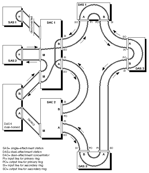
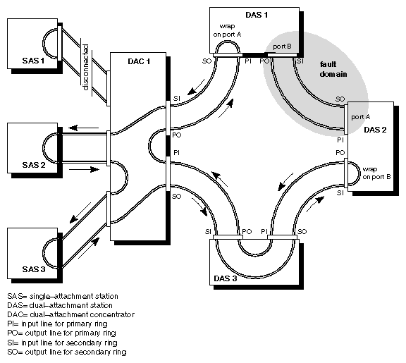
The break that is causing the fault domain illustrated in Figure In-2 could be a dysfunction of any of the following:
the cable lying between DAS1 and DAS2
the output connector for the primary ring (PO, one line of port B) at DAS1
the input connector for the primary ring (PI, one line of port A) at DAS2
a component on the adapter board for transmitting at DAS1 or for receiving at DAS2 on the primary ring
Notice that a powered-off or dysfunctional SAS (illustrated by SAS1 in both Figure In-1 and Figure In-2) does not cause the ring to wrap.