This chapter describes how to install the FDDIXPress controller board into a Silicon Graphics system. A separate section is dedicated to each platform.
 | Caution: This product is not customer installable. Installation of this product requires specific training and technical knowledge. These instructions have been provided for use by Silicon Graphics, Inc., System Support Engineers or other Silicon Graphics trained personnel only. This installation requires the installer to handle internal electrical power that is hazardous if the equipment is improperly disassembled or reassembled. |
This section describes the steps for installing FDDIXPress into a POWER Series or Professional Series workstation or server. A maximum of four FDDIXPress boards can be installed into these systems.
 | Note: If you are installing the FDDIXPress board into the VMEbus-B of a Predator 3 (R2-4D POWER Center), you must have FDDIXPress 2.0 (or higher) and IRIX 4.0.1 or higher since this configuration is not supported in the earlier release. |
Verify that the system's operating system version (IRIX or eoe1) matches the version of FDDIXPress that you are going to install. Software compatibility information is located in the FDDIXPress Release Notes. If necessary, upgrade the operating system.
Once the system is ready to install FDDIXPress, perform a system backup and verify the saved files.
Use this command to check if the FDDIXPress software has been installed:
% /usr/sbin/versions FDDIXPress
I FDDIXPress 03/02/93 FDDIXPress 3.1 Option
If the software is installed and the version is correct, proceed to the next step.
If the message Nothing satisfies the selection criteria is displayed or if the version is not correct, install FDDIXPress software using the IRIX installation method and the Inst commands install FDDIXPress and go.
Configure the FDDI network interface, as explained in the FDDIXPress Release Notes or in Chapter 2 of the FDDIXPress Administration Guide.
If installing more than one FDDIXPress board, verify that each board's JA11 jumper is set to a unique unit number. Refer to Figure 1-2 for details.
Attach the board's cables (1 optical bypass switch cable and two fiber optic cables) to the board.
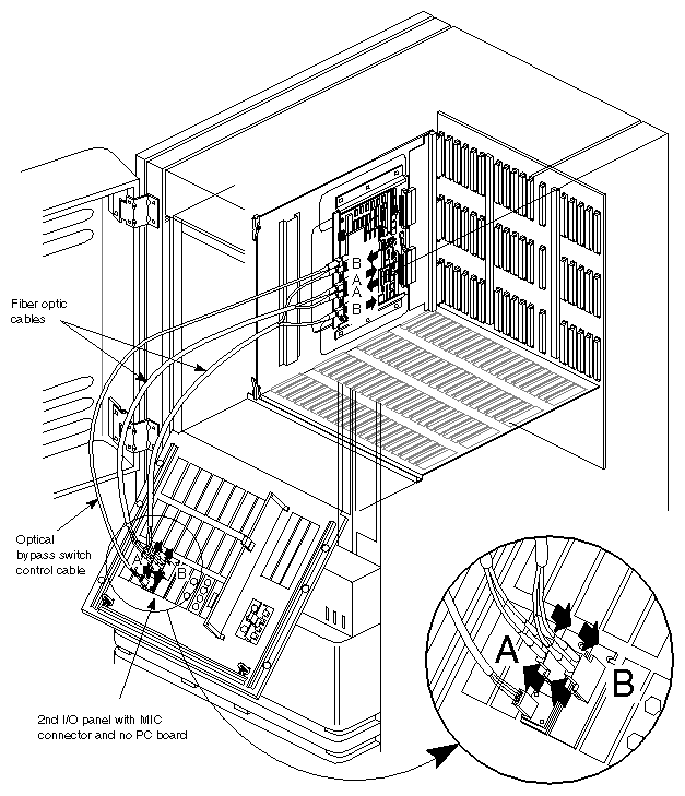
Each of the two fiber optic cables has a pair of ST™ connectors (each marked with an arrow indicating the direction of its signal). The ST connectors must be attached as illustrated in Figure 1-1, making sure to match cable A to the board's port A receptacles and cable B to the board's port B receptacles.
Caution: If the ST connectors are not connected properly, the FDDI connection will not work. Attach the optical bypass switch cable to the board and to the panel plate, as illustrated in Figure 2-2.
| Caution: The components are extremely sensitive to ESD (electrostatic discharge). Use proper antistatic procedures while handling all components. |
Shut down the system according to the operating system instructions.
Turn off the power switch and unplug the power cable.
Remove the keyboard, Ethernet, SMD, ESDI, monitor or RGB cables, and any other cables from the I/O door.
Open the I/O door on your system.
Caution: On a Twin Tower (POWER Station system) remove the bottom screw located on the I/O door between the hinges. If you do not remove this screw, the sheet metal could be damaged during disassembly. Select a VMEbus slot for the FDDIXPress board. It is recommended that you select the first available VMEbus slot. (If you leave any VMEbus slots empty, you must jumper them as explained in Section 2.1.5.1, "Backplane Considerations.") Refer to Table 2-1 through Table 2-6 to help determine the proper slot.
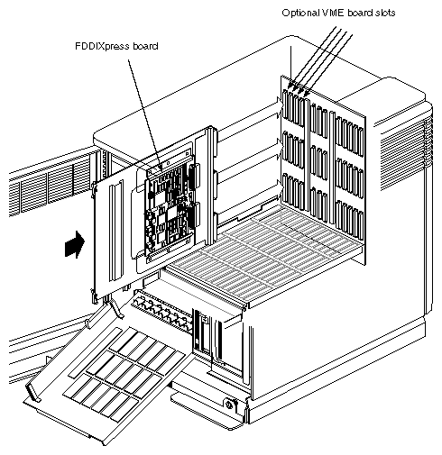
Install the FDDIXPress board and extender board into the VMEbus slot. See Figure 2-1 for an example of installing an FDDIXPress board into a system.
Attach the two mounting panel plates to two different openings in the I/O panel door.
Finish the installation by following the instructions in Section 2.5, "Completing Board Installation."
Table 2-1. Professional Series or Omni IRIS-4D/85GT(Diehard1) VMEbus Slot Allocations
Slot
IRIS-4D 60G 12-Slot Multi-Board Computer (MBC)
IRIS-4D 7/80 GT 12-Slot Single-Board Computer (SBC)
IRIS 4-D 85GT 13-Slot Chassis
1
CPU board only
CPU board only
CPU board only
2
FPP board only
Memory board (pre-empted VMEbus slot)
Memory board (or optional VMEbus board)
3
Memory board only
Memory board (pre-empted VMEbus slot)
Memory board (or optional VMEbus board)
4
Memory board only
ESDI Controller board (pre-empted VMEbus slot)
ESDI Controller board
5
Memory board only
CMC Ethernet Controller (pre-empted VMEbus slot)
CMC Ethernet Controller
6
Optional VMEbus board
ISI tape controller (or optional VMEbus board)
ISI tape controller (or optional VMEbus board)
7
Optional VMEbus board
Optional VMEbus board
Optional VMEbus board
8
Optional VMEbus board
GE4
GE4
9
Optional VMEbus board
GM1
GM1
10
GF3
RM1
RM1
11
DE3
RV1
RM1
12
TB2
RM1
RV1.5
13
N/A
N/A
Optional Video Board (for example VP1)
| Note: The Omni IRIS-4D/85GT backplane adheres to the same practice as prior Silicon Graphics backplanes. All unused slots must have jumpers H71, HUB3, H7B2, H7B1 and H7BG pinned. |
Table 2-2. Single Tower (Diehard II) VMEbus Slot Allocations
Slot Number | Slot Type |
|---|---|
1 | Optional VMEbus board |
2 | Optional VMEbus board |
3 | Optional VMEbus board |
4 | Optional VMEbus board |
5 | I/O board |
6 | CPU board |
7 | Optional CPU board |
8 | MC2 board |
9 | GM board |
10 | GE board |
11 | RM board |
12 | RM board |
13 | DG1 board |
14 | Optional video board |
Table 2-3. Twin Tower VMEbus Slot Allocations
Slot Number | Slot Type |
|---|---|
1 | Optional VMEbus board |
2 | Optional VMEbus board |
3 | Optional VMEbus board |
4 | Optional VMEbus board |
5 | I/O board |
6 | CPU board |
7 | Optional CPU board |
8 | MC2 board |
9 | MC2 board |
10 | GM board |
11 | GE board |
12 | RM board |
13 | Optional RM board |
14 | DG1 board |
15 | Optional video board |
Table 2-4. POWER Center (Predator) VMEbus Slot Allocations
Slot Number | Slot Type |
|---|---|
1 | Optional VMEbus board |
2 | Optional VMEbus board |
3 | Optional VMEbus board |
4 | Optional VMEbus board |
5 | Optional VMEbus board |
6 | Optional VMEbus board |
7 | I/O board |
8 | 1st CPU board |
9 | 2nd CPU board (if applicable) |
10 | 3rd CPU board (if applicable) |
11 | 4th CPU board (if applicable) |
12 | MC2 board |
13 | MC2 board |
14 | GM board |
15 | GE board |
16 | RM board |
17 | Optional RM board |
18 | DG1 board |
19 | Optional video board |
Table 2-5. R2-4D POWER Center (Predator 3) VMEbus Slot Allocations
Slot Number | Slot Type |
|---|---|
1 | Optional VMEbus-A board |
2 | Optional VMEbus-A board |
3 | Optional VMEbus-A board |
4 | Optional VMEbus-A board |
5 | Optional VMEbus-A board |
6 | Optional VMEbus-A board |
7 | 1st IO3 board |
8 | 1st CPU board |
9 | 2nd CPU board (if applicable) |
10 | 3rd CPU board (if applicable) |
11 | 4th CPU board (if applicable) |
12 | 1st MC2 board |
13 | 2nd MC2 board (if applicable) |
14 | 2nd IO3 board |
15 | Optional VMEbus-B board |
16 | Optional VMEbus-B board |
17 | Optional VMEbus-B board |
18 | Optional VMEbus-B board |
19 | Optional VMEbus-B board |
Table 2-6. SkyWriter VMEbus Slot Allocations
Slot Number | Board |
|---|---|
1 | Optional VMEbus board |
2 | Optional VMEbus board |
3 | Optional VMEbus board |
4 | Optional VMEbus board |
5 | Pipeline 1 optional video board |
6 | Pipeline 1 DG1 board (optional EV1 board) |
7 | Pipeline 1 RM3 board |
8 | Pipeline 1 RM3 board |
9 | Pipeline 1 GE6 board |
10 | Pipeline 1 GM3 board |
11 | IO2 or IO3 board |
12 | IP board |
13 | IP board |
14 | MC2 board |
15 | Pipeline 0 GM3 board |
16 | Pipeline 0 GE6 board |
17 | Pipeline 0 RM3 board |
18 | Pipeline 0 RM3 board |
19 | Pipeline 0 DG1 board with VX1 board |
20 | Pipeline 0 Optional video board |
This section contains information about special installations such as backplane considerations when you skip a VMEbus slot, configuration instructions when you install into a second card cage, and information specific for a particular platform.
After you have inserted the FDDI board into an empty VMEbus slot, you may need to add jumpers to the backplane. You may also need to reconfigure the /usr/sysgen/system file if you are installing the board into the VMEbus B channel (indicated as VMEbus-B) of a dual VMEbus R2-4D rackmount chassis.
When the POWER Series IRIS-4D boots after power-on, it probes its I/O channels to identify the hardware that is plugged into each VMEbus slot. The power-up sequence probes each VMEbus slot sequentially until reaching the last used slot in each
I/O channel. It must find either a VMEbus I/O controller or jumpers in each VMEbus slot location. If the slots aren't properly jumpered, the workstation or server will hang before booting or never enable the new hardware.
Whether or not you need to add jumpers to the backplane is determined by two factors:
the VMEbus slot chosen
the backplane of the workstation or server
You need to reconfigure the /usr/sysgen/system file only if you are installing the FDDI board into the VMEbus-B channel of a dual VMEbus R2-4D rackmount chassis.
When you are adding VMEbus boards into several chassis, keep the following general rules in mind:
For the IRIS-4D Professional Series (which includes the IRIS-4D 60, 70, 80, and 85 models), remove the existing VMEbus backplane jumpers from the slot when you add a VMEbus board. All unused slots must be jumpered.
For the IRIS-4D POWER Series (IRIS 120/GTX and later), add the VMEbus board into the first available VMEbus in numerical sequence without leaving any gaps. Jumpering the unused slots is unnecessary. However, if VMEbus boards are added out of numerical sequence leaving gaps, you must add jumpers to the slots that were skipped.
For the R2-4D dual VMEbus model 19-slot rackmount chassis, the /usr/sysgen/system file must be reconfigured for new VMEbus boards.
There is no prescribed sequence of VMEbus boards that is necessary. In the past, SSEs were advised to add disk controllers first, then add Ethernet controllers second. These sequences were designed for consistency, not electronic necessity. All VMEbus boards are serviced by the backplane according to the board's priority interrupt level, not by the slot order.
| Note: If you need to skip a slot to fit oversized VMEbus boards or to improve airflow in a chassis, make sure that you jumper only the slots corresponding to empty slots; don't jumper slots that actually house VMEbus boards! |
When a R2-4D system is configured with dual IO3s, the VMEbus boards can be added either to the VME bus A or to VMEbus B. Add the VMEbus boards into the lowest slot number for each of VMEbus-A and VMEbus-B. See Table 3-5. As Table 3-5 shows, slot 1 is the first slot location for VMEbus-A and slot 15 is the first slot location for VMEbus-B.
If you are adding FDDIXPress boards into the VMEbus-A (slots 1-6), you won't have to edit the system configuration file /usr/sysgen/system file; the default settings allow you to add to up to four FDDIXPress boards into VMEbus-A. However, once you start adding FDDIXPress boards into VMEbus-B, the base and probe values in the /usr/sysgen/system must be edited to locate those devices on VMEbus-B. Once the file has been edited, a new kernel must be generated and booted. Information on how to do so is included in the comments in the /usr/sysgen/system file, and a summary of this information as it applies to an FDDIXPress board installation follows.
The FDDIXPress board appears in the /usr/sysgen/system file as module=if_ipg. The default entries for the FDDIXPress board cover four FDDIXPress boards on VMEbus-A. Each FDDIXPress board has a base VMEbus address specified by the lower 16 bits of supervisor space. These addresses are the same whether the FDDIXPress board is on VMEbus-A or VMEbus-B. These values are indicated in bold italicized text. The file presents the fourth FDDIXPress board first, and it is designated as unit=3. Truncated versions of the VMEbus-A entries (so that you can see what numbers remain the same) are shown below:
unit=3 base=0xB7C1B400 exprobe=(r, 0xB7C1B402,2,0xfdd1,0xffff) unit=2 base=0xB7C1B200 exprobe=(r, 0xB7C1B202,2,0xfdd1,0xffff) unit=1 base=0xB7C1AE00 exprobe=(r, 0xB7C1AE02,2,0xfdd1,0xffff) unit=0 base=0xB7C1AC00 exprobe=(r, 0xB7C1AC02,2,0xfdd1,0xffff) |
The lines shown above are for VMEbus-A FDDIXPress boards. To add an FDDIXPress board into VMEbus-B, the high order bits for the base and probe locations must be changed for each board added into the chassis. The changes are shown below in bold text:
unit=3 base=0xB781B400 exprobe=(r, 0xB781B402,2,0xfdd1,0xffff) unit=2 base=0xB781B200 exprobe=(r, 0xB781B202,2,0xfdd1,0xffff) unit=1 base=0xB781AE00 exprobe=(r, 0xB781AE02,2,0xfdd1,0xffff) unit=0 base=0xB781AC00 exprobe=(r, 0xB781AC02,2,0xfdd1,0xffff) |
To add three FDDIXPress boards to a dual VMEbus R2 rackmount chassis, follow these steps:
After unpacking the FDDIXPress boards, check the JA11 jumper on the first board to make sure that it has the correct jumper settings for the first board, shown in Figure 1-3 as unit 0.
Change the jumper settings on the second FDDIXPress board to the unit 1 settings, as shown in Figure 1-3.
Change the jumper settings on the third FDDIXPress board to the unit 2 settings, as shown in Figure 1-3.
Add unit 0 into slot 1.
Add unit 1 into slot 15.
Add unit 2 into slot 16.
Become superuser and open the /usr/sysgen/system file under the vi screen editor.
Caution: Always make a copy of files before making any line changes. Locate the appropriate vector lines corresponding to the device (or board) name. Find this line for the unit 0 FDDI board:
VECTOR: module=if_ipg vector=0xc7 ipl=4 unit=0 base=0xB7C1AC00 exprobe=(r, 0xB7C1ACO2,2,0xfdd1,0xffff)
Since the first board is going to be part of VMEbus-A bus, you don't have to change this line.
The entries for unit=1 and unit =2 must be changed for VMEbus-B. In each of the unit=1 and unit=2 lines, replace the 0xB7C in the base address and probe address to 0xB78, as shown in bold italicized text:
VECTOR: module=if_ipg vector=0xc5 ipl=4 unit=2 base=0xB781B200 exprobe=(r, 0xB781B202,2,0xfdd1,0xffff)
VECTOR: module=if_ipg vector=0xcd ipl=4 unit=1 base=0xB781AE00 exprobe=(r, 0xB781AE02,2,0xfdd1,0xffff)
VECTOR: module=if_ipg vector=0xc7 ipl=4 unit=0 base=0xB7C1AE00 exprobe=(r, 0xB7C1AC02,2,0xfdd1,0xffff)
Save your changes and exit the file.
Reboot to rebuild the kernel.
Note: When updating a kernel using Inst, a new /usr/sysgen/system file is created with all base and interrupt addresses in the default (VMEbus-A) range. Before executing autoconfig to configure a new kernel, the relevant VMEbus-B addresses must be merged into /usr/sysgen/system from /usr/sysgen/system 0. If it is not, the operating system will not find any of the I/O devices on VMEbus-B when the system boots.
| Caution: Remember, the fiber in the cable is made of glass and is therefore breakable. Do not overly bend, flex, or tug on a fiber cable. |
Remove the plate coverings from two connector cutouts from the back of the I/O panel.
Note: Two I/O panel connectors are used per FDDI board. For example, if you are installing two FDDI boards, you need four I/O panel slots. Install the media interface connectors (MICs) into the exposed slots. See Figure 2-2.
Attach the fiber optic cables to the connectors on the FDDI board. Make sure that the direction of the arrow on each cable matches the connector and that cable A is connected to the board's port A connectors and cable B is connected to the board's port B connectors, as illustrated in Figure 1-1.
Attach the Optical Bypass Switch (OBS) to the board by following the instructions that accompanied the OBS.
Attach the other ends (the MICs) of each cable to the appropriate A and B panel plates.
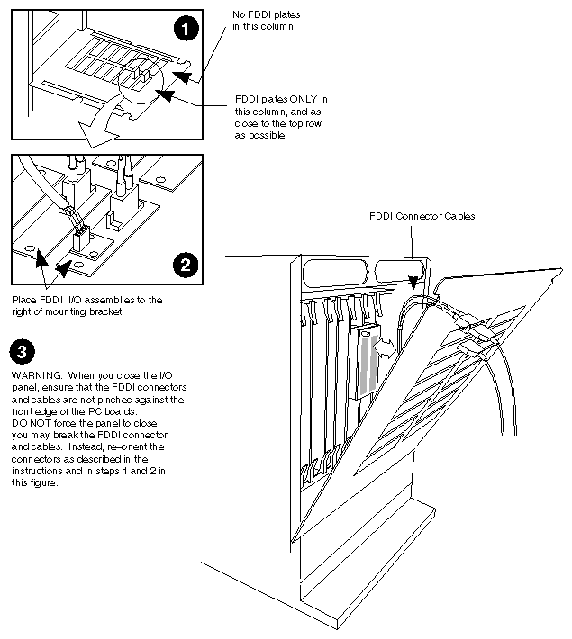
Because of the narrow distance between the PC board and the back of the I/O panel on the Twin Tower chassis, special I/O plate assembly installation is required. See Figure 2-3.
Always install the I/O plate assemblies in the left column panel slots. Never install the plate assemblies in the right column in the top two slots.
If possible, place the plate assemblies in the top two slots.
Ensure that the fiber optic cables are attached to the A and B connectors on the FDDI board. Make sure that the direction of the arrows on the cable match up with the connector. In addition, ensure that the Optical Bypass Switch cable is attached. See Figure 2-2.
Caution: The FDDI connector and cable may push against the front of the PC boards; be careful when closing the I/O panel after installation. Close the panel carefully to see if the FDDI connector and cables come in contact with the front edge of the PC boards. See Figure 2-3. Ensure that the connector and cables do not pinch against the boards.
This section describes the steps for installing FDDIXPress into an IRIS Crimson workstation or server. A maximum of four FDDIXPress boards can be installed into a Crimson system.
Verify that the system's operating system version (IRIX or eoe1) version matches the version of FDDIXPress that you are going to install. Software compatibility information is located in the FDDIXPress Release Notes. If necessary, upgrade the operating system.
Once the system is ready to install FDDIXPress, perform a system backup and verify the saved files.
Use this command to check if the FDDIXPress software has been installed:
% /usr/sbin/versions FDDIXPress
I   FDDIXPress   date   FDDIXPress version Option
If the software is installed and the version is correct, proceed to the next step.
If the message Nothing satisfies the selection criteria is displayed or if the version is not correct, install FDDIXPress software using the IRIX installation method and the Inst commands install FDDIXPress and go.
Configure the FDDI network interface, as explained in the FDDIXPress Release Notes or in Chapter 2 of the FDDIXPress Administration Guide.
If installing more than one FDDIXPress board, verify that each board's JA11 jumper is set to a unique unit number. Refer to Figure 1-2 for details.
Attach the board's cables (1 optical bypass switch cable and two fiber optic cables) to the board.
Each of the two fiber optic cables has a pair of ST connectors (each marked with an arrow indicating the direction of its signal). The ST connectors must be attached as illustrated in Figure 1-1, making sure to match cable A to the board's port A receptacles and cable B to the board's port B receptacles.
Caution: If the ST connectors are not connected properly, the FDDI connection will not work. Attach the optical bypass switch cable to the board and to the panel plate, as illustrated in Figure 2-2.
Shut down the system according to the operating system instructions.
Turn off the power switch and unplug the power cable.
Remove the keyboard, Ethernet, SMD, ESDI, monitor, or RGB cables, and any other cables from the I/O door.
Open the I/O door on your system.
Caution: The components are extremely sensitive to ESD (electrostatic discharge). Use proper antistatic procedures while handling all components. Select a VMEbus slot for the FDDIXPress board. It is recommended that you select the first available VMEbus slot. (If you leave any VMEbus slots empty, you must jumper them as explained in Section 2.1.5.1, "Backplane Considerations.")
Install the FDDIXPress board and extender board into the VMEbus slot. See Figure 2-1 for an example of installing an FDDIXPress board into a system.
Attach the two panel plates to two different openings in the I/O panel door.
Finish the installation by following the instructions in Section 2.5, "Completing Board Installation."
This section describes the steps for installing FDDIXPress into a Challenge L (also known as Challenge deskside) or Challenge XL (also known as Challenge rackmount) system. A maximum of four FDDIXPress boards can be installed into a Challenge system.
Verify that the system's operating system version (IRIX or eoe1) matches the version of FDDIXPress that you are going to install. Software compatibility information is located in the FDDIXPress Release Notes. If necessary, upgrade the operating system.
Once the system is ready to install FDDIXPress, perform a system backup and verify the saved files.
Use this command to verify that the FDDIXPress software has been installed:
% /usr/sbin/versions FDDIXPress
I   FDDIXPress   date   FDDIXPress version Option
If the software is installed and the version is correct, proceed to the next step.
If the message Nothing satisfies the selection criteria is displayed or if the version is not correct, install the FDDIXPress software, using the IRIX installation method and the Inst commands install FDDIXPress and go.
Configure the FDDI network interface, as explained in the FDDIXPress Release Notes or in Chapter 2 of the FDDIXPress Administration Guide.
If installing more than one FDDIXPress board, verify that each board's JA11 jumper is set to a unique unit number. Refer to Figure 1-2 for details.
Attach the board's cables (1 optical bypass switch cable and two FDDI cables) to the board.
Each of the two FDDI cables has a pair of ST connectors (each marked with an arrow indicating the direction of its signal). The ST connectors must be attached as illustrated in Figure 1-1, making sure to match cable A to the board's port A receptacles and cable B to the board's port B receptacles.
Caution: If the ST connectors are not connected properly, the FDDI connection will not work. Attach the optical bypass switch cable to the board, as illustrated in Figure 2-2.
Disconnect the MIC connectors (on the FDDI cables) from their previous panel plates (two). Then, attach both MICs to the new Challenge panel plate (only one). Be sure to match the MICs to the labels on the plate.
Attach the optical bypass switch cable to the new mounting plate.
Shut down the system according to the operating system instructions.
Turn off the power and unplug the power cable.
Remove all cables from the I/O door.
Open the I/O door on the system.
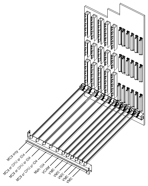
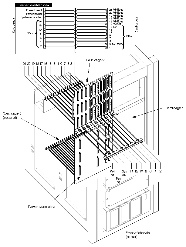
Caution: The components are extremely sensitive to ESD (electrostatic discharge). Use proper antistatic procedures while handling all components. Select a VMEbus slot for the FDDIXPress board. It is recommended that you use the first available VMEbus slot. For a Challenge L (deskside) system, see Table 2-7 and Figure 2-4 for additional information. For a Challenge XL (rackmount) system, see Table 2-8 and Figure 2-5.
Verify that a power supply board has been installed for the VMEbus slot(s) you have selected. On a Challenge L (deskside) system, VMEbus power supply boards are installed at the back of the system, on the other side of the VMEbus connectors. On a Challenge XL (rackmount) system, VMEbus power supply boards are installed in card cage 1.
Install the FDDIXPress board and extender board into the VMEbus slot. The side of the board with most of the components faces to your right, as illustrated in Figure 2-1.
If you decide not to use the first available VMEbus slot, follow the instructions in the system's installation instruction manual to jumper the empty slots.
Attach the panel plate to the I/O panel door.
Close the I/O door on the system.
Finish the installation following the instructions in Section 2.5, "Completing Board Installation."
Table 2-7. Challenge L Board Slot Allocation
Slot Number
Board Type
1
Not to be used for VMEbus boards
2
Not to be used for VMEbus boards
3
Not to be used for VMEbus boards
4
Not to be used for VMEbus boards
5
Not to be used for VMEbus boards
6
IO4 and VCAM (VMEbus Channel Adapter Module)
7
First VMEbus Board
8
Second VMEbus Board
9
Third VMEbus Board
10
Fourth VMEbus Board
11
Fifth VMEbus Board
Table 2-8. Challenge XL Board Slot Allocations
Slot Number, Card Cage
Board Type
1, Card Cage 2
Not to be used for VMEbus boards
2, Card Cage 1
Not to be used for VMEbus boards
3, Card Cage 2
Not to be used for VMEbus boards
4, Card Cage 1
Not to be used for VMEbus boards
5, Card Cage 2
Not to be used for VMEbus boards
6, Card Cage 1
Not to be used for VMEbus boards
7, Card Cage 2
Not to be used for VMEbus boards
8, Card Cage 1
Not to be used for VMEbus boards
9, Card Cage 2
Not to be used for VMEbus boards
10, Card Cage 1
Not to be used for VMEbus boards
11, Card Cage 2
Not to be used for VMEbus boards
12, Card Cage 2
Not to be used for VMEbus boards
13, Card Cage 2
Not to be used for VMEbus boards
14, Card Cage 2
Not to be used for VMEbus boards
15, Card Cage 2
Main IO4
16, Card Cage 2
VCAM
17, Card Cage 2
First VMEbus board
18, Card Cage 2
Second VMEbus board
19, Card Cage 2
Third VMEbus board
20, Card Cage 2
Fourth VMEbus board
21, Card Cage 2
Fifth VMEbus board
This section describes the steps for installing FDDIXPress into an Onyx deskside or Onyx rackmount system. A maximum of three FDDIXPress boards can be installed into an Onyx deskside system; a maximum of four FDDIXPress boards can be installed into an Onyx rackmount system.
Verify that the system's operating system version (IRIX or eoe1) matches the version of FDDIXPress that you are going to install. Software compatibility information is located in the FDDIXPress Release Notes. If necessary, upgrade the operating system.
Once the system is ready to install FDDIXPress, perform a system backup and verify the saved files.
Use this command to verify that the FDDIXPress software has been installed:
% /usr/sbin/versions FDDIXPress
I   FDDIXPress   date   FDDIXPress version Option
If the software is installed and the version is correct, proceed to the next step.
If the message Nothing satisfies the selection criteria is displayed or if the version is not correct, install the FDDIXPress software, using the IRIX installation method and the Inst commands install FDDIXPress and go.
Configure the FDDI network interface, as explained in the FDDIXPress Release Notes or in Chapter 2 of the FDDIXPress Administration Guide.
If you are installing more than one FDDIXPress board, verify that each board's JA11 jumper is set to a unique unit number. Refer to Figure 1-2 for details.
Attach the board's cables (one optical bypass switch cable and two fiber optic cables) to the board.
Each of the two fiber optic cables has a pair of ST connectors (each marked with an arrow indicating the direction of its signal). The ST connectors must be attached as illustrated in Figure 1-1, making sure to match cable A to the board's port A receptacles and cable B to the board's port B receptacles.
Caution: If the ST connectors are not connected properly, the FDDI connection will not work. Attach the optical bypass switch cable to the board, as illustrated in Figure 2-2.
Disconnect the MIC connectors (on the fiber optic cables) from their previous mounting plates (two plates). Then, attach both MICs to the Challenge mounting plate (only one). Be sure to match the MICs to the labels on the plate.
Attach the optical bypass switch cable to the new mounting plate.
Shut down the system according to the operating system instructions.
Turn off the power key and unplug the power cable.
Remove all cables from the I/O door.
Open the I/O door on the system.
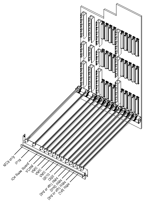
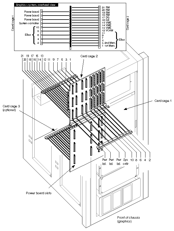
Caution: The components are extremely sensitive to ESD (electrostatic discharge). Use proper antistatic procedures while handling all components. Select a VMEbus slot for the FDDIXPress board. It is recommended that you use the first available VMEbus slot. For an Onyx deskside system, refer to Table 2-9 and Figure 2-6 for VMEbus slot information. For an Onyx rackmount system, refer to Table 2-10 and Figure 2-7.
Verify that a power supply board has been installed for the VMEbus slot(s) you have selected. On an Onyx deskside system, VMEbus power supply boards are installed at the back of the system, on the other side of the VMEbus connectors. On an Onyx rackmount system, VMEbus power supply boards are installed in card cage 1.
Install the FDDIXPress board and extender board into the VMEbus slot. The side of the board with the majority of the components faces to your right, as illustrated in Figure 2-1.
If you decide not to use the first available VMEbus slot, follow the instructions in the system's installation instruction manual to jumper the empty slots.
Attach the mounting plate to the I/O panel door.
Close the I/O door on the system.
Finish the installation following the instructions in Section 2.5, "Completing Board Installation."
Table 2-9. Onyx Deskside Board Slot Allocations
Slot Number
Board
1
Not to be used for VMEbus boards
2
Not to be used for VMEbus boards
3
Not to be used for VMEbus boards
4
IO4 and VCAM (VMEbus Channel Adapter Module)
5
First VMEbus board
6
Second VMEbus board
7
Third VMEbus board
8
Not to be used for VMEbus boards
9
Not to be used for VMEbus boards
10
Not to be used for VMEbus boards
11
Not to be used for VMEbus boards
12
Not to be used for VMEbus boards
13
Not to be used for VMEbus boards
Table 2-10. Onyx Rackmount Board Slot Allocations
Slot Number / Card Cage
Board
1 Card Cage 2
Not to be used for VMEbus boards
2 Card Cage 1
Not to be used for VMEbus boards
3 Card Cage 2
Not to be used for VMEbus boards
4 Card Cage 1
Not to be used for VMEbus boards
5 Card Cage 2
Not to be used for VMEbus boards
6 Card Cage 1
Not to be used for VMEbus boards
7 Card Cage 2
Not to be used for VMEbus boards
8 Card Cage 1
Not to be used for VMEbus boards
9 Card Cage 2
Not to be used for VMEbus boards
10 Card Cage 1
Not to be used for VMEbus boards
11 Card Cage 2
Not to be used for VMEbus boards
12 Card Cage 2
IO4 and VCAM (VMEbus Channel Adapter Module)
13 Card Cage 2
First VMEbus option board
14 Card Cage 2
Second VMEbus option board
15 Card Cage 2
Third VMEbus option board
16 Card Cage 2
Not to be used for VMEbus boards
17 Card Cage 2
Not to be used for VMEbus boards
18 Card Cage 2
Not to be used for VMEbus boards
19 Card Cage 2
Not to be used for VMEbus boards
20 Card Cage 2
Not to be used for VMEbus boards
21 Card Cage 2
Not to be used for VMEbus boards
Once you have installed the board(s), follow these steps. It is important to verify that each board is working properly before you connect the new FDDI station to the site's ring.
Ensure that the I/O door is closed.
Connect the main power cord.
Attach all previously removed cables to the I/O panel.
Turn on the main power switch.
If the Power On tests pass, access the System Maintenance Menu; type 1 to start the operating system.
When prompted with Automatically rebuild the operating system?, respond yes. This step builds the FDDIXPress driver (ipg driver) into the kernel.
When the system comes up again, access the System Maintenance Menu and again start the operating system. This second restart boots from (starts using) the newly built operating system.
Log on.
If you are using a graphical display monitor, open a window shell. For nongraphics systems, go to the next step.
At the prompt, type /bin/hinv. You should get a display similar to the following:
1 50 MHZ IP17 Processor
FPU: MIPS R4010 Floating Point Chip Revision: 0.0
CPU: MIPS R4000 Processor Chip Revision: 2.2
On-board serial ports: 4
Data cache size: 8 KBytes
Instruction cache size: 8 KBytes
Secondary unified instruction/data cache size: 1 MByte
Main memory size: 16 MBytes
I/O board, slot F: IO3B
Integral Ethernet: et0, IO3
FDDIXPress Controller; ipg0, Version 1
FDDIXPress Controller; ipg1, Version 1
IRIS TokenRing controller fv0: 16 Mbit
VGX Graphics option installed
Integral SCSI controller 1: Version WD33C93A, revision 9
Tape drive: unit 2 on SCSI controller 0: QIC 150
Disk drive: unit 1 on SCSI controller 0
Integral SCSI controller 0: Version WD33C93A, revision 9
Note: You must issue the /bin/hinv command from the operating system, not the PROM monitor. Verify that the FDDIXPress Controller line is displayed.
Connect the MICs on the I/O panel to the site's matching MICs (A-to-A and B-to-B when connecting directly to the dual ring or B-to-S when connecting to one M port on a concentrator or A-to-S and B-to-S when connecting to two M ports).
Verify that the FDDI network connection is functional by following the instructions in Chapter 2 of the FDDIXPress Administration Guide.