This chapter contains the following sections:
This chapter provides an overview of the configuration requirements for each RAID box. It also explains how to properly extend or terminate the SCSI bus connected to each RAID box.
Figure 2-1 shows the proper configuration of the sled board for use in the RAID array.
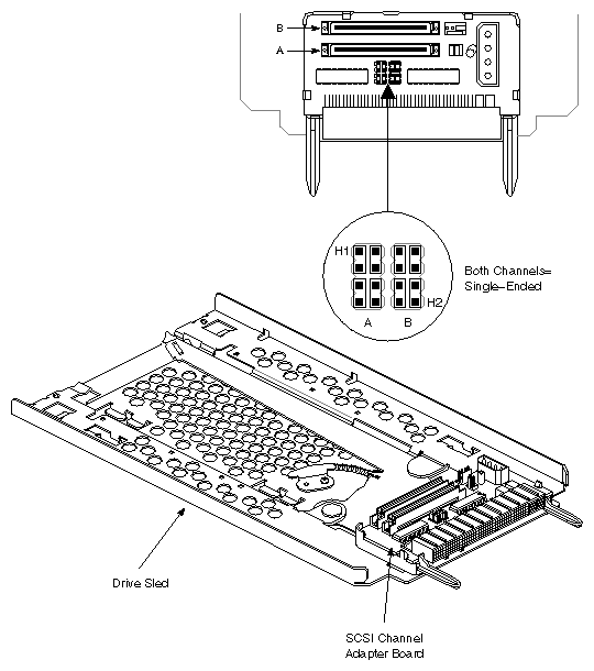
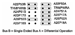
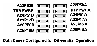
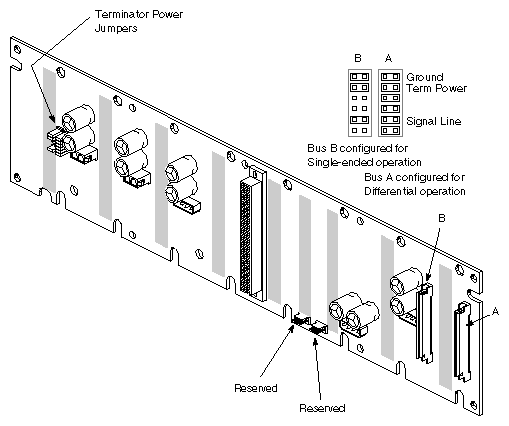
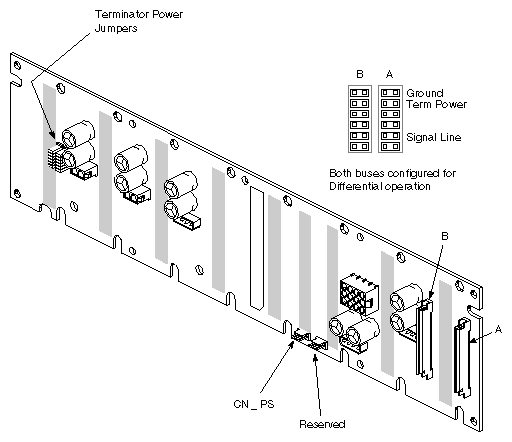
As noted in Chapter 1, "Introducing the RAID Hardware Options", the functionality of the SCSI backplane in the RAID box is different from the ones in the non-RAID SCSIBox 2 products. The jumpering concepts for the RAID backplane, however, are similar to those for the non-RAID box. Use Figure 2-2 and Figure 2-3 to configure the jumpers on a RAID box backplane to use single-ended or differential non-RAID drives in bays 0 and 1 in a RAID box.
Use of optional single-ended non-RAID devices in bay 0 or 1 requires a specific jumper configuration on the backplane in addition to proper RAID jumpering. See Figure 2-2.
The location of the backplane jumpers on the rear of the "stubby" box RAID backplane is shown in Figure 2-4. Note that the 512S power brick is not shown installed. To reset the backplane jumpers, you will probably have to remove the 512S.
Figure 2-5 shows the location of the backplane jumpers on the rear of the Vault RAID box backplane. The location of the CN_PS connector that links to the Vault box power supply is also indicated.
In a non-RAID SCSI-based system, each device on the bus must have an individual SCSI ID number. In a RAID application, the SCSI ID numbering is done in a two-tier configuration. The system's IO4 SCSI controller interface actually only "sees" the RAID controller ID number. The RAID controller in turn communicates with the five disks in the array in a specific disk identification pattern. All the disks "behind" the RAID controller SCSI ID are treated as one large SCSI disk.
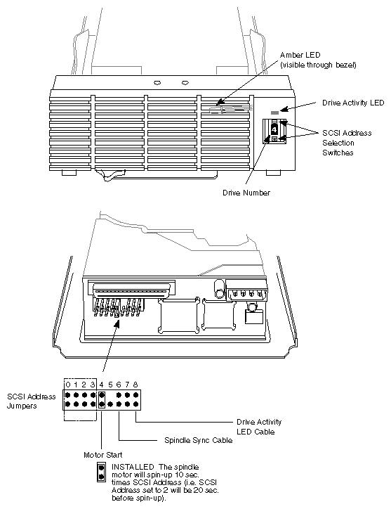
The five drives in each RAID must use 0 through 4 for their drive IDs. From left to right, the drives should be numbered 0, 1, 2, 3, and 4. Use the push buttons on either side of the ID panel to select the proper SCSI ID. See Figure 2-6.
After replacing a defective disk, be sure to select the proper SCSI ID (0-4) for the new device. The RAID controller will not recognize a disk that has a duplicate ID or an ID other than 0-4.
The RAID controller board has a rotary selection switch that allows you to designate IDs 0 through F as the target SCSI ID of the RAID array. Never set the RAID controller for SCSI ID 0, as this ID is reserved for the (IO4) SCSI controller board.
 | Note: If the RAID array is on the same SCSI bus as the system disk, you must not assign the RAID a SCSI ID of 1. SCSI ID 1 is always used for the system disk. |
The RAID controller assembly is always shipped from the factory with a default SCSI ID setting of 2. Use the hinv inquiry to the system to be sure of the SCSI IDs assigned to other devices on the SCSI bus. If an existing device on the bus has SCSI ID 2, you must either change the setting on that device or alter the setting on the RAID controller. For additional information on accessing the RAID controller, see Section 3.5.1, "Controller Assembly Removal and Replacement" in Chapter 3. Use the following information to set the ID:
Access the left side of the controller assembly and locate the rotary switch at position U87 in the upper middle section of the board. See Figure 2-7 for the exact location.
Set the SCSI ID for the controller by turning the arrow to the number you have selected. Do not select ID 0.
Reinstall the controller assembly.
There are four configuration jumper blocks on the RAID controller board that must be configured properly for the array to operate. See Table 2-1 for their proper configuration and functions. Refer to Figure 2-7 for their locations.
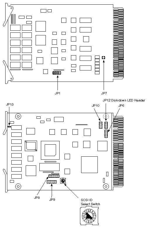
Table 2-1. RAID Controller Jumper Configurations and Functions
Location | Pin Numbers | Jumper In/Out | Function(s) |
|---|---|---|---|
JP-1 | 1-2 | In | RAID channel 0 termination |
| 3-4 | In | RAID channel 1 termination |
| 5-6 | In | RAID channel 2 termination |
| 7-8 | In | RAID channel 3 termination |
| 9-10 | In | RAID channel 4 termination |
| 11-12 | Out | Host SCSI termination enable |
JP-7 | 1-2 | Out | Local Host SCSI TERMPWR |
| 3-4 | Out | Remote Host SCSI TERMPWR |
JP-8 | 1-2 | Out | PRI/SEC, RS-232 Options (not supported) |
| 3-4 | Out |
|
| 5-6 | Out |
|
| 7-8 | Out |
|
| 9-10 | Out |
|
| 11-12 | Out |
|
| 13-14 | Out |
|
| 15-16 | Out |
|
JP-13 | 1-2 | In | Internal LED enable |
These restrictions apply to non-RAID devices that you install in a RAID box:
Non-RAID devices are only allowed in bay 0 or 1
The device(s) must be differential if they are controlled by the same SCSI bus as the RAID array or are in a Vault rack.
If the non-RAID devices are single-ended, they must be controlled by a separate SCSI bus (system rack only).
This section is concerned with cabling in both the drive assembly and the RAID box.
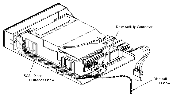
The SCSI ID and LED function cable is on the left-hand side of the disk and sled assembly (when viewed from the rear). This cable supports three separate functions, as shown in Figure 2-8. The cabling on the disk assembly should already be fully connected. If it is not, reference Section A.4, "Converting Existing Drives" in Appendix A.
The RAID channel (A) on either variation of the RAID box must be terminated with a differential termination plug. If channel B (the non-RAID channel) is not being used, it does not need to be terminated.
 | Caution: Using a single-ended terminator on the RAID channel termination plug will cause SCSI bus malfunction. |
Each drive assembly has an LED disk-down signal cable that connects from jumper block CN4 (pins 1 and 2 only) on the drive sled to the LED connection on the front panel. This cable must be connected with the red stripe closest to the power connector for the amber disk-down LED to light up when a disk-down event occurs. See Figure 2-8 for the location of the cable.
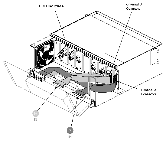
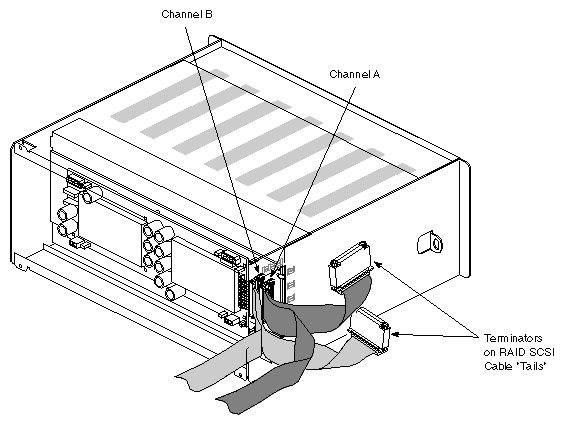
A significant difference between the standard SCSIBox2 and the RAID boxes is that the RAID SCSI box backplane does not have terminator plugs. On Vault-mounted RAID boxes, termination is supplied by continuing the incoming SCSI cable back out to the termination port.
In system rack "stubby" RAID boxes, the terminators connect directly to the "tail" of the incoming SCSI RAID cable and are routed back to a plastic retainer bracket on the outside of the system rack chassis. See Figure 2-9 for the Vault RAID box example and Figure 2-10 for the system-mounted "stubby" RAID box example.
The SCSI cable that connects to the "stubby" system rack RAID box backplane is different from the Vault RAID box because it uses a non-fixed termination point. Daisy chaining to another box or device from a "stubby" RAID box is not supported as it is in the Vault-mounted boxes.