This appendix contains the following sections:
The upgrade process from using non-RAID SCSI boxes to RAID boxes requires that the customer have five Silicon Graphics-supplied 2.0 GB IBM SCSI disks for each RAID upgrade. These disks use a 68-pin FAST (10 Megatransfers) and WIDE (16-bit) SCSI-2 interface and have special firmware parameters programmed. The RAID box will not work with other types of drives.
Each RAID upgrade kit should have the following:
A RAID SCSI box with RAID backplane and controller interface board assembly
System Rack box (P/N 013-0664-00x)
Vault Rack box (P/N 013-0665-00x)
A RAID controller assembly and disk-down LED cable (should be already installed in the RAID box)
Five 5-inch (12.7 cm) spindle sync connector cables (P/N 015-0151-00x)
A 1.5-foot (0.47 m) 68-pin daisy-chaining SCSI cable (P/N 9290051)
An 8.2-foot (2.5 m) power cord (P/N 9350053)
A 25-foot (7.6 m) SCSI cable for Vault-mounted boxes (P/N 9290102)
A 6-foot (1.8 m) internal RAID cable set for system racks (P/N 018-0415-00x)
For safety and electrostatic discharge (ESD) precautions, refer to the beginning of Chapter 3, "Installing the RAID Box" and follow the guidelines.
Fully back up or transfer information from all the 2.0 GB disks that will be used for the new RAID installation. During RAID formatting, all existing information will be overwritten. Shut down the system chassis or expansion rack and open the bottom outer door to access the SCSI boxes.
 | Note: If you are uncertain about the proper shutdown procedure, refer to Section 3.2, "Powering Down the Chassis" in Chapter 3. |
Tools you will need for this upgrade procedure include:
A medium size Phillips screwdriver
A medium size flat-bladed screwdriver
A number T7 Torx® driver
A 1/8-inch (3.2 mm) hex (Allen) wrench
If the 2.0 GB drives for the upgrade are already removed, go to Section A.4, "Converting Existing Drives" for instructions on converting them for use in the RAID box. If the 2.0 GB disks that will be converted to RAID use have not been removed from the existing SCSIBox 2, use the following steps to extract them:
Twist open the fasteners at the top of the box door and lower it into a fully open position.
Working from right to left, lift the drive-sled locking lever into the unlocked position on each of the drives you wish to remove.
Remove the drives and close and secure the SCSI box door.
The non-RAID 2.0 GB drive must be converted before being used in the RAID SCSI box. Use the instructions in Section A.4, "Converting Existing Drives" to convert each drive that you will install in the RAID.
If the customer wishes to continue using the SCSI box from which you have removed the 2.0 GB drives, it may be left in place. It can be used with remaining or additional non-RAID devices. The information in the following steps is aimed at removal of a Vault-mounted box; removal/replacement of a box in the system rack is a more complex procedure. Reference Chapter 3, Section 3.3, "Installing a RAID Box in the System Rack," for details on the "stubby" box.
If it is necessary to remove the non-RAID box in order to make room for installation of the new RAID box, use the following steps:
Push the SCSI box's front power switch to the Off position (Vault SCSI boxes only).
Note: You may want to remove any remaining drives from the box to make it easier to handle as you remove it. See steps one through three in the previous section for the procedure. The Vault-mounted SCSI box weighs approximately 37 pounds (16.8 kg) with all drives removed. Access the rear of the SCSI box and unplug the power cord and SCSI cable(s).
Use the 1/8-inch (3.2 mm) hex-head (Allen) wrench to remove the four screws (two on either side of the box) that connect the box to the front rails. Note that the "stubby" box has only one screw on each side.
Carefully pull the box out of the chassis and lift it free. See Figure A-1.
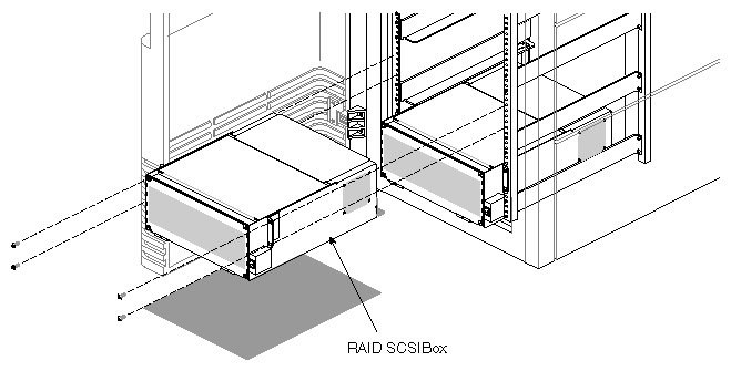
There are three basic processes that must be accomplished before a disk is ready for installation in a RAID box:
Moving the drive position back, placing it closer to the adapter board
Installation of cables between the drive and sled adapter board
Note: Use only the screws that came with the drive/sled assembly. Screws that are too long can short-circuit components on the drive.
You will need a number T7 Torx driver and medium-sized Phillips-head and flat-bladed screwdrivers to accomplish the conversion modifications on the disk/sled assembly. When you have completed the tasks listed in the following steps, you will be ready to install the disk and sled assembly into the RAID box:
Set the disk on a flat, non-conductive surface and remove the power and SCSI connectors from the differential converter board on the back of the disk.
Using the Torx driver, remove the two screws at either end of the differential converter board.
Unplug the converter board from the back of the 2.0 GB disk and set it aside. The converter board is the customer's property and should be left on-site.
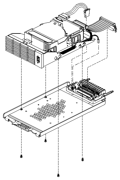
Undo the four Phillips-head screws (two on either side) that hold the disk to the sled assembly. See Figure A-2.
Unscrew the four slot-head screws (two on either side of the disk) and move the disk back (toward the sled board) approximately a half inch (12.5 mm) to the next set of screw holes and resecure the disk with the four screws.
Remount the disk assembly to the sled with the four Phillips-head screws.
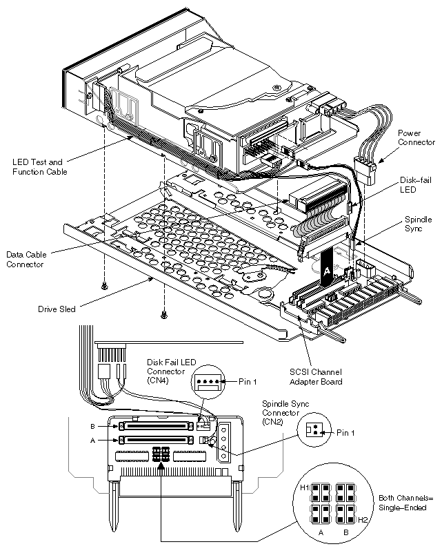
Plug one end of the 68-pin bridge cable into channel A on the adapter board and the other into the back of the disk, then reconnect the power plug to the disk. See Figure A-3.
Note: Be sure to plug the 68-pin cable into the channel A connector. The RAID array will not work if any of the disks are connected to channel B.
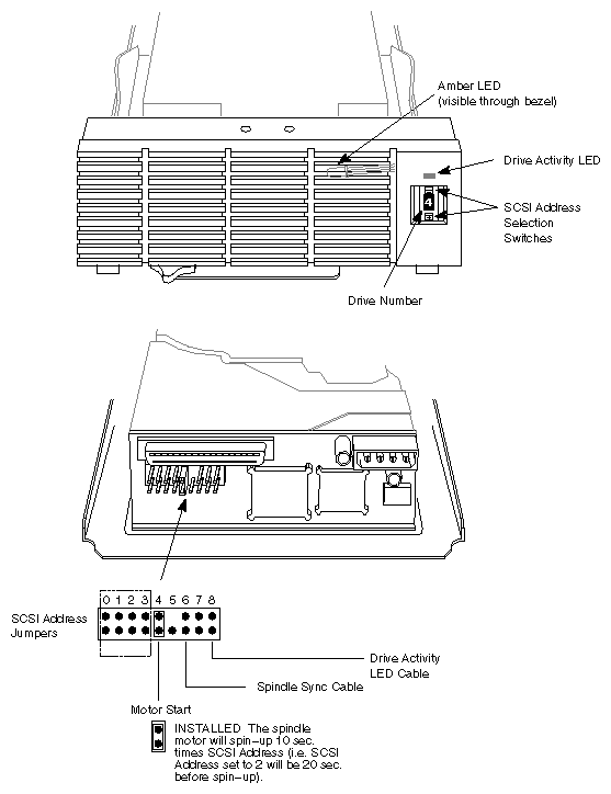
Plug a spindle sync cable onto position CN2 on the sled adapter board with the red wire on pin 2, closest to the disk drive. Refer to Figure A-3. Connect the other end to the row header at position 6 (third from the right) on the nine-row header on the rear of the 2.0 GB disk. The red wire must be in the lower position. See Figure A-4.
Confirm that the LED fault cable is plugged into pins 1 and 2 of header CN4 on the sled adapter board. The red wire should be on pin 1 (closest to the power connector).
This section contains a brief description of how to install the new RAID box and the controller and drives that go in it.
The following installation procedures apply mainly to the Vault-mounted RAID box. Installing and cabling a RAID box in a system rack is a more complex and time-consuming procedure than installing one in the Vault rack. The original non-RAID SCSI cables will have to be removed, and new system rack RAID cables installed and connected. Reference Chapter 3, Section 3.3, "Installing a RAID Box in the System Rack," for details on the "stubby" box.
Use the following basic steps to install the RAID box:
| Note: For easier loading, it is recommended that the drives be inserted after the box is installed. |
Lift up the SCSI drive box and install it into the first set of rails on the bottom. Always start with the lowest position available, then work your way up.

Caution: If you install the drive boxes in only the top portion of the Vault, the rack could tip over when you try to remove them. Secure the SCSI drive box to the vertical rails on the chassis using two screws for the box in the system rack and four on the Vault-mounted box.
If you have multiple drive boxes in a Vault chassis, install the second box directly above the first box, and so on.
Use filler plates as required to cover open areas on the front of the Vault chassis.
| Note: See the instructions and figures in Chapter 3, "Installing the RAID Box" if you need more detailed information on the procedures. |
After you have installed the RAID box(es) and attached all necessary cables, the RAID disks can be inserted.
Before installing drives, be sure that the following configuration requirements are met:
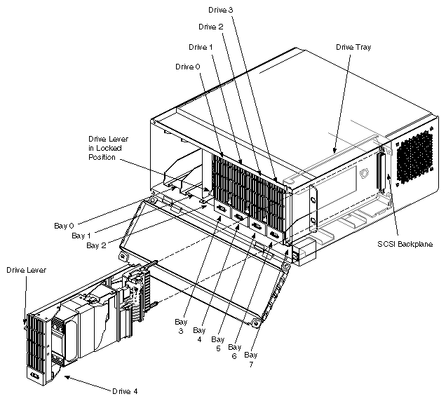
To install or remove a drive, follow these instructions and see Figure A-5.
Hold the drive sideways, with the top of the drive facing right and the bottom of the drive sled facing left. See Figure A-5.
Install the drive sled assembly into the drive tray in bay 3 and slide it all the way into place, then push the drive lever down. The drive module should click into place, flush with the slot, and should not come out when you pull it.
Repeat this process for drive bays 4 through 7 in the RAID box.
Install non-RAID devices only in bay 0 or 1. See Section 3.6, "Installing a Full-height Non-RAID Drive" in Chapter 3 if necessary.
Close and fasten shut the RAID SCSI box door after you install all of the drives.
Caution: The front door of the RAID box must be in place during operation for proper air flow to cool the drives and to comply with FCC and other regulatory requirements. To remove a drive, push the drive lever up and then slide the module out.
| Caution: The SCSI box does not have a set of safety rails to hold it in place. If you have drives installed, never pull the RAID box too far out on the railing. It may fall and cause damage to equipment or personnel. |
The RAID controller board assembly ships from the factory installed with the disk-down LED cable already connected. If you should need to replace a controller for any reason, use the information in Section 3.5.1, "Controller Assembly Removal and Replacement" in Chapter 3.
When all installation/upgrade work is completed, you should power on the system and check to see that the RAID drives are on line. Use the power on procedures in Section 3.7, "Powering On the System" at the end of Chapter 3.
| Note: After you have enabled power to the RAID box, push the small, square reset button at the bottom of the RAID controller board. Refer to Figure 1-5 if you are unsure of its location. When you push this reset button, the disk-down cable function is tested and all the amber fault LEDs should light up. The controller goes through a hardware reset. |
See Chapter 4 in the RAID System Administration Guide to configure and bring the new RAID drives on line.