This chapter contains the following sections:
This chapter provides an overview of the Silicon Graphics® implementation of a Redundant Array of Inexpensive Disks (RAID). If you are not familiar with RAID subsystems, or are not aware of the features and limitations of Silicon Graphics RAID products, read this chapter. For purposes of brevity, the term RAID in this manual refers to the Silicon Graphics functional implementation as defined in this chapter.
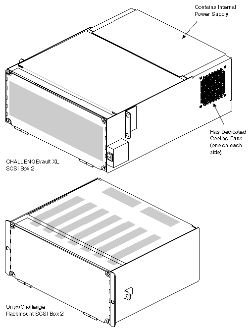
The SCSI RAID subsystems offered by Silicon Graphics are installed in a variation of the eight-bay SCSIBox 2 drive enclosure that was introduced with the CHALLENGE and Onyx products. The principal difference between a RAID box and non-RAID SCSIBox 2 is the backplane and the RAID adapter board and controller that plug into the backplane of the RAID SCSI box. The RAID version of the "stubby" SCSI box that installs only in the main system rack uses the same power brick as the non-RAID SCSIBox 2. Note that there is no internal RAID configuration for deskside systems. Deskside systems connect to RAID boxes installed in a Vault (T2) expansion rack. See Figure 1-1 for an example of the two.
Customers who wish to upgrade their installed CHALLENGE/Onyx systems to use RAID may keep and use existing 2.0 GB IBM SCSI disks purchased from Silicon Graphics. A new RAID SCSI box is required for the upgrade. See Appendix A, "RAID Hardware Upgrades"for details on upgrades to existing systems.
Silicon Graphics RAID subsystems offer the following features:
Choice of RAID 3 or RAID 5 implementation
A Vault rack filled with RAID boxes supportable by one SCSI channel
Two optional non-RAID 5 1/4" SCSI devices supportable in each RAID box
Hot unplugging/plugging of a defective RAID disk during system operation
Controller status and "disk-down" warning LEDs
Programmable stripe depth from 2KB to 64KB per disk
SCSI-2 FAST and WIDE host interface
The RAID subsystem is redundant only to the extent that a single disk failure will not cause loss of data. This presumes that a new disk is properly installed and software recovery is properly executed as soon as possible. There is no redundant power supply for the RAID box.
In the RAID implementation, a set of five disks is controlled by a disk array controller that resides in bay two of the RAID box. Bay zero is always reserved for a non-RAID device, and bay one can be an additional non-RAID SCSI device. Future system software and hardware releases may support a second RAID controller in bay one. Note that a disk in bay 0 can share the same SCSI bus as the RAID array, but it must be a differential device. Any single-ended device installed in bay 0 or 1 has to be controlled by a separate single-ended SCSI channel. See Table 1-1 for an overview of the requirements for each bay in the RAID SCSI box.
Table 1-1. Use of Each Bay in the RAID SCSI Box
Bay Number | Use of the Bay |
|---|---|
0 | Optional Non-RAID SCSI Device |
1 | Optional Non-RAID SCSI Device |
2 | RAID Controller Assembly Location |
3 | RAID Disk 0 |
4 | RAID Disk 1 |
5 | RAID Disk 2 |
6 | RAID Disk 3 |
7 | RAID Disk 4 |
 | Note: Single-ended non-RAID devices can be installed only in RAID boxes that are in the main system chassis. They are not supported in the Vault (T2) expansion rack. |
Regardless of whether the implementation is RAID 3 or 5, the disk arrays will use the exclusive OR (XOR) process to generate parity and reconstruct lost data. When one of the disks in the array fails, an XOR strategy will be used to restore the information on the replaced disk. In an XOR strategy, the parity bit that is written to a disk will always be the bit that leaves the array write pattern in a "true" state. The array will only be in a true state if there is an even number of 1's written to the five disks. Figure 1-2 shows a very simple example of the XOR parity concept. Disk 4 contains the parity bit and disk 1 is a failed disk. For simplification, the bits shown below the disks represent the last bit written in each 2KB stripe written across a disk.
For example, suppose our RAID array (disks 0 through 4) experiences a failure of disk 1. Because there is now an odd number of ones (three), the array is in a non-true state. When the failed disk (disk 1) is replaced, the system can restore the proper bit (a one) to the new disk 1. The reconstruction program knows that the bit must be a one, because without the original disk 1, there is an odd number of ones written across that stripe subsection in the array.
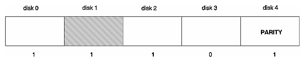
If the array in the previous example were a RAID 3 implementation, the parity bit would always be written to disk 0. Disk 0 would be the dedicated parity disk.
If the array in Figure 1-2 were a RAID 5 implementation, the parity bit could be written to any of the disks in the array. RAID 5 uses a section of each disk as a parity disk and spreads the parity bits across the array. See the following two subsections, Section 1.2.1, "RAID 3 Implementation," and Section 1.2.2, "RAID 5 Implementation,"for more on RAID 3 and 5.
In the RAID 3 application, one of the five disks in the array is reserved exclusively for parity data. This allows the performance improvement of disk striping while removing the problems related to data loss if a single disk in the stripe group fails. In a non-RAID group of striped disks, loss of a single disk would mean loss of all data.
The RAID 3 operation is different from RAID 5 in that the parity bits cannot be written to any but the designated parity disk. Note that Silicon Graphics uses a block-striped RAID 3 implementation.
The drawback to a RAID 3 implementation is that writing to a disk in the group means accessing all the disks in the group. Basically this means that the level 3 RAID can perform only one I/O at a time. RAID 3 striping provides fewer I/O's per second than either straight disk striping or RAID 5 implementations.
Use of the dedicated parity disk has drawbacks when multiple write operations are requested at the same time. The parity has to be written to the dedicated disk on each requested write, which can produce an I/O bottleneck.
In a RAID 5 application, the concept of striping with parity redundancy is expanded by spreading out the parity information to all the disks in the array rather than having a dedicated parity disk as in RAID 3. Using a section of each disk as a parity disk means the writing of parity bits will be spread out relatively evenly across the disk array.
A performance improvement results because a user can write a segment to disk 0 and parity to disk 1, while another user writes a segment to disk 2 and parity to disk 3. This improves what is called the "transactional" speed of the RAID subsystem. Transactional processing speed is important when many users want access to the disks to read and write data quickly. Since RAID level 5 allows almost tandem accesses, bottleneck problems with I/O are less likely than in RAID level 3.
A RAID 5 array cannot produce write performance that equals straight disk striping, since other operations are needed to make and store the parity bits. When any part of a stripe is modified, the non-modified parts must also be read and parity generated for the entire stripe. After parity generation, the modified data and parity information must be written to the disk; this is generally called a read/modify/write strategy.
| Note: RAID 5 is not supported in IRIX release 5.0.1. |
Each Silicon Graphics RAID subsystem always consists of a five-disk array and one RAID controller. Future system software and hardware releases are expected to support a second controller. The features offered with Silicon Graphics RAID have been discussed, but it is also important for the system support engineer (SSE) to understand what features are not offered.
The following RAID features are not supported in the Silicon Graphics RAID subsystem:
Disk mirroring
Hot plugging (removal and replacement) of an active controller
Hot plugging of more than one disk at a time
Use of an on-line "hot spare"
Fewer than five disks in the RAID array
More than five disks in the RAID array
Note: The RAID array cannot be used as the system disk and the system cannot boot from the RAID array.
The most important concept to remember when hot unplugging/plugging a disk in the RAID array is to be absolutely sure you are removing the failed disk. If one disk has failed and a different one is removed, the system will experience a double point of failure. The probable result of this will be loss of data across the entire RAID array. Reloading and reformatting from tape backups will probably be necessary.
There will be a noticeable decrease in performance after a failed disk has been replaced. This is due to the overhead required by the reconstruction program to rebuild the information that was on the failed disk onto the replacement disk. See Chapter 4 in the RAID System Administration Guide P/N 007-2113-001.
| Note: A disk that is signaling imminent failure or needs to be removed for other reasons should always be marked "down" before it is removed. Verify the disk ID and slot number using the information in this chapter. See the RAID System Administration Guide for specific instructions on how a disk is marked down. |
There are four methods for determining which disk in the RAID array is malfunctioning.
You should check at least two of the following indications of failure before hot plugging a replacement disk:
A lit disk-down LED on the disk's front panel
A lit disk-down LED on the RAID controller
A direct inquiry to the IRIX™ shell
A disk failure message in /var/adm/SYSLOG
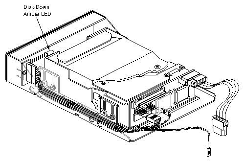
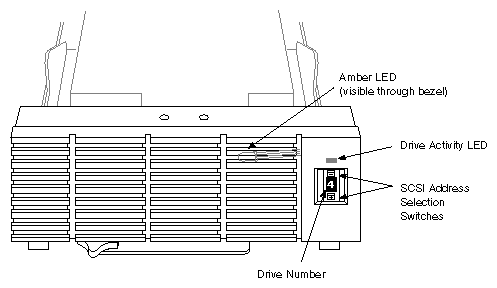
The RAID controller lights the amber disk-down indication LED that is visible behind the plastic and metal front panel of each disk. This LED will light when the disk experiences a failure. Figure 1-3 shows the location of the disk-down indication LED behind the disk's front panel. Figure 1-4 shows the disk-down LED from the front of the drive.
There are a set of eight LEDs on the forward edge of the RAID controller board. The error indication on the RAID controller LED should reflect the error indication shown on the individual disk. If it does not, use one of the procedures in the following two subsections to reconfirm the failure.
See Table 1-2 for a description of all the functions of the RAID controller's eight LEDs.
Table 1-2. RAID Controller LEDs
LED | Lit Means | Off Means | Flashing Means |
|---|---|---|---|
1 | The RAID is processing commands. | The RAID is not processing commands. | The RAID is processing commands. |
2 | The RAID has failed. | The RAID has failed. | The RAID is operating normally. |
3 | A maintenance command such as building a disk drive or checking parity is active. | The RAID is operating normally. | A maintenance command such as building a disk drive or checking parity is active. |
4 | Disk drive 0 is down. | Disk drive 0 is operational. | N/A |
5 | Disk drive 1 is down. | Disk drive 1 is operational. | N/A |
6 | Disk drive 2 is down. | Disk drive 2 is operational. | N/A |
7 | Disk drive 3 is down. | Disk drive 3 is operational. | N/A |
8 | Disk drive 4 is down. | Disk drive 4 is operational. | N/A |
See Figure 1-5 for location and identification of the RAID controller board disk-down LEDs.
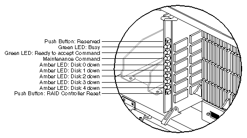
You can check on the status of all RAIDs connected to the system by using a direct command to the IRIX shell. Enter the following in any functional IRIX shell:
% raid -c |
If the command line returns no information, there are no down disks.
If you just need to check on the status of a particular RAID array, become superuser and enter:
# raid -c /dev/rdsk/radcontrollerdunitvh |
This returns information on only the specified device. No information is returned if there is no down disk found.
Note that when the system is rebooted, all RAIDs are checked for failed disks automatically using the command:
% raid -c -m -L |
The -m option tells the raid command to check for disks that were replaced while the system was off. If it finds new disks, it marks them as down and any data on them is not used. The -L writes any messages to /var/adm/SYSLOG and the console window. See the rebuild information in Chapter 4 of the RAID System Administration Guide.
Remember that a standard hinv inquiry from the IRIX shell sees the RAID array as a single disk. A response from the hinv inquiry regarding a RAID might look like the following:
Disk drive: unit 1 on controller 1: RAID |
If you are in the PROM "Command Monitor" level on the system, hinv is unable to distinguish between RAID and non-RAID disks. The response you would receive to an hinv inquiry is similar to:
Disk drive: unit 1 on controller 1 |
The fact that unit 1 is a RAID array is not specified as it is when IRIX is operational.
You can check in /var/adm/SYSLOG for information on failed disks. The information written to SYSLOG should indicate that disk XX attached to RAID array XX and controller XX failed on a given day and time.
If the system has more than one RAID array connected, you should always check carefully to be sure there is not more than one failure.
Each RAID disk monitors its internal statistical information. The RAID controller monitors the soft error rate on each disk in the array and can use the information to predict an imminent disk failure. The RAID subsystem uses sophisticated predictive failure analysis (PFA) to provide warnings predicting that disks are statistically likely to fail within 24 hours. See the RAID System Administration Guide for more information on this topic.
When a disk reaches an error rate that indicates failure within 24 hours, a message is sent to /var/adm/SYSLOG and to the system console.
If /var/adm/SYSLOG contains warning messages that indicate both a failed disk and an imminent failure for another disk, it is imperative that the failed disk be replaced immediately. Replace the disk labeled as an imminent failure as soon after that as possible.
If the RAID box is experiencing multiple failures, the failures should be remedied in the following priority order:
A failed controller assembly
A down disk
A disk marked as an imminent failure
Each RAID SCSI box can be daisy chained to the next until the Vault rack is filled and they can be connected to a single SCSI controller. This is the allowed maximum number of RAIDs on a single SCSI controller. In practice, the customer will probably want far fewer RAIDs connected to each controller in order to maintain maximum throughput on the SCSI bus.
To promote the best system I/O throughput, the following guidelines are recommended for RAIDs:
The rated capacity of a fast and wide channel is 20 MB per second, but because of overhead, assume that the capacity is 18 MB per second.
A RAID 3 at maximum throughput uses most of the capacity of a channel.
A RAID 5 at maximum throughput uses about one quarter of the capacity of a channel.
For RAID 5, the sizes of the transfers and the number per second determine how many transfers (and therefore RAIDs) can fill the capacity of the channel.
A non-RAID disk at maximum throughput uses 3 MB to 4 MB per second.
Putting slow devices such as tape drives and CD-ROM drives on a channel with one or more RAID units can severely impact the performance of the RAIDs.
In general, RAID units should be put on channels with other RAID units and non-RAID disk drives only.
| Note: All SCSI controller connections made to RAID boxes must be from differential IO4 SCSI connectors. |
Do not attempt to use the following SCSI controllers to support RAID boxes:
The VME-based 4210 and 4220 differential SCSI controllers
Single-ended IO4 SCSI buses
IO2 or IO3 SCSI controller boards
Any third-party supplied SCSI controller
When connecting multiple RAID boxes in a Vault, be sure not to exceed the maximum differential SCSI cable length of 81 feet (25 meters). Be sure to include the following lengths when calculating SCSI bus distance from the controller: