This chapter contains the following sections:
This chapter provides information on installing RAID boxes into both the system rack and the Vault expansion rack. It is presumed that the installer has some experience with the Challenge/Onyx rackmounted products. Expanded background information on these chassis is available in the CHALLENGE/Onyx Rackmount Installation Instructions, part number 108-7042-0x0 and CHALLENGE Vault Rackmount and SCSIBox 2 Installation Instructions, part number 108-7044-0x0.
 | Caution: Installation of the RAID product requires specific training and technical knowledge. These instructions are provided for use by Silicon Graphics system support engineers or other Silicon Graphics-trained technical personnel. |
This equipment is susceptible to damage caused by electrostatic discharge (ESD). Use standard ESD precautions and the following preventive measures whenever possible:
Connect a ground strap to your wrist when connecting/disconnecting all peripherals.
Keep boards and drives in their antistatic bags until they are ready for installation.
This section covers the power-off procedure for the system rack and the Vault (T2) expansion rack. If the system is already powered off, proceed to the appropriate section and begin the RAID box installation.

The system rack should be completely powered down before installing the RAID box. Before beginning this procedure, log out and shut down the software using the instructions that follow:
To halt operating system activity and prepare the system for power-off, become superuser and enter /etc/halt in a functional IRIX shell. The /etc/halt command will gracefully shut down the system software and leave you at the firmware monitor level. If you are remotely logged in to the system, you will be prompted before the shutdown procedure is executed.
Turn the System Controller key switch to the Off position to eliminate all power to boards, peripherals, and (if applicable) the Vault expansion rack.
Switch the system circuit breaker to the Off position to eliminate power to the off-line switcher (OLS) and backplane.
Unplug the power cord from the socket to cut off all electrical power to the system.
Use the following instructions to install or remove the RAID SCSI box drive enclosures:
Power down the system as described in the previous section.
Unpack the RAID SCSI box and check for any obvious shipping damage.
Remove the side panels from the left side of the system chassis.

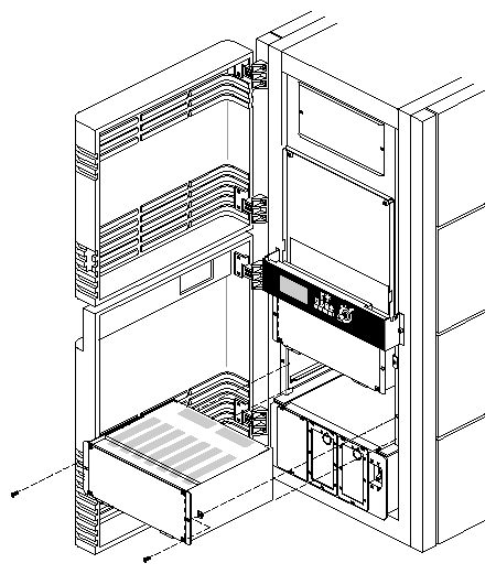
Note: Use care when handling the side panels. Store them in a safe place during this procedure to avoid scratching or marring them. Slide the RAID box into the enclosure until the flange on either side of the box contacts the system chassis. Fasten the box in place with one screw on each side. See Figure 3-1 for an example.
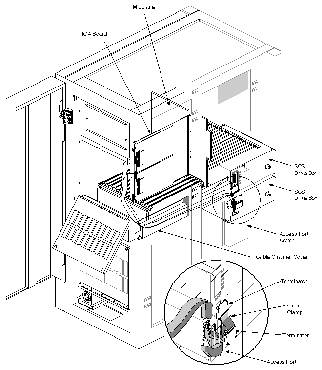
Remove the access port cover (12 nuts) and locate the two SCSI cables and the power cable for the optional RAID SCSI box. The SCSI cables run down the left side of the system chassis and exit from the cable routing box immediately to the rear of the RAID SCSI box access ports. The power cables are integral to the access port cover. Reference Figure 3-2.
Caution: You must use only a RAID SCSI cable (P/N 018-0415-00x) to connect a RAID box to a differential controller on the IO4. The RAID SCSI box cannot be terminated without use of the RAID SCSI cable. Use steps six and seven if you need to install a RAID SCSI cable, otherwise continue to step eight. Remove the Phillips-head screws securing the cable channel cover. Pull the non-RAID SCSI cable out and carefully install a new RAID SCSI cable set (if applicable).
Reinstall the cable channel cover.
Route the differential RAID SCSI cable past the unattached SCSI cable and into the lower access port and connect it to the channel A connector on the RAID box.
Attach the additional RAID SCSI cable to channel B if you want to support non-RAID devices in bay 0 or 1 of the RAID box using a separate SCSI channel.
Note: Verify that the bus designations on the cables and on the RAID box connectors they are attached to match. No daisy-chaining is allowed between RAID boxes in a system rack. Each box must be connected to a separate SCSI controller. Route the terminated "tails" of the RAID SCSI cables back out the access port.
Attach an adhesive plastic bracket to the sheet metal just above the access port and confine the terminated cable "tails" so that the shortest is in a vertical position flush with the chassis sheet metal. The longer "tail" should droop forward back over the front of the bracket and hang flush with the access port. If a second RAID box is installed in the upper bay, tuck the terminated SCSI cable "tails" into the horizontal cable channel box.
Connect cable A to a differential SCSI connector on the IO4.
If needed, connect cable B to a differential or single-ended SCSI connector on the IO4.
Connect the power cable to the pigtail attached to the 512S power board.
Install the RAID disks and controller, and any other drives intended for the RAID box. See Section 3.5, "Installing the Drives and Controller" later in this chapter. Be sure all hardware configuration has been implemented as discussed in Chapter 2, "Configuring the RAID Hardware."
Reinstall the access port cover and shielded power cables.
Reinstall the side panels.
Close up the unit and power on the system (use the information in Section 3.7, "Powering On the System").
The following installation procedure applies only to the Challenge Vault RAID box and not the "stubby" RAID box that installs into a Challenge or an Onyx rackmount system.
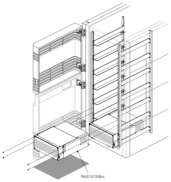
Lift up a SCSI drive box and install it into the first set of rails on the bottom. Always start with the lowest available set of rails, then work your way up. See Figure 3-3.
Caution: If you install the drive boxes in only the top portion of the Vault, the rack could tip over when you try to remove them. Secure the SCSI drive box to the vertical rails on the chassis using two screws on each side. The location of the screws is also shown in Figure 3-3.
If you have multiple drive boxes, install the second box on top of the first box, and so on.
Use filler plates as required to cover open areas on the front of the chassis.
Route the 25 foot (7.6 m) SCSI cable from the host system to the Vault rack.
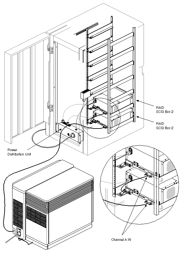
Connect the cable to channel A on the first (or only) RAID box. Daisy-chain additional boxes using the 1.5 foot (0.47 m) daisy-chain SCSI cable. See Figure 3-4 for a connection example.
After you have installed the RAID box(es) and attached all necessary cables, the RAID disks can be inserted.
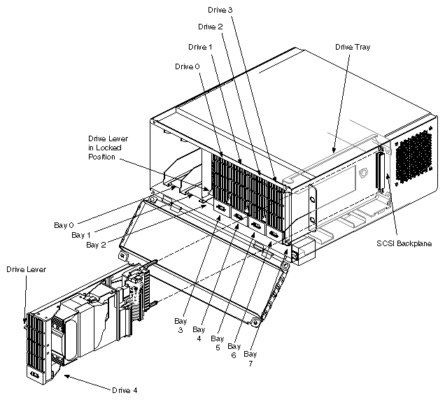
To install or remove a disk, follow these instructions and see Figure 3-5.
Hold the disk assembly sideways, with the top of the disk facing right and the bottom of the drive sled facing left.
Install disk and sled assembly 0 into the drive tray in bay 3 and slide it all the way into place, then push the drive lever down. The disk module should click into place, flush with the slot, and should not come out when you pull it.
Repeat this process for disk bays 4 through 7 in the RAID box (RAID disks 1-4).
Install non-RAID drives only in bay 0 or 1. See Section 3.6, "Installing a Full-height Non-RAID Drive" if necessary.
Close and fasten the RAID box cover after you install all of the drives.
To remove a disk, push the drive lever up and then slide the module out.
Caution: The SCSI drive box does not have a set of safety rails to hold it in place. If you have drives installed, never pull the drive box too far out on the railing. It may fall and cause damage to equipment or personnel.
The RAID controller board assembly ships from the factory already installed with the disk- down LED cable connected. If you should need to replace a controller for any reason, use the information in the next section.
Remove a controller board using the following steps:
Take all the drives in the RAID box off line and power off the box.
Use a small Phillips-head screwdriver to undo the screw at the front of the bent L- shaped metal retainer at the front of the controller.
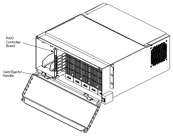
Remove the retainer and use the plastic ejector handles at the top and bottom of the assembly to carefully pull the controller out of the box. Try not to snag the disk-down LED cable on the left side of the assembly.
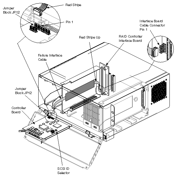
Locate and unplug the disk-down LED cable connected to the RAID controller board at plug location JP12. See Figure 3-6.
Install a new controller board using the following information:
Take the controller board assembly out of its antistatic packaging and align it so that the green LEDs are facing you and are in the top position.
Plug one end of the disk-down LED cable into jumper JP12 on the lower left portion of the board (furthest from the LEDs). The red stripe on the cable indicates which end of the connector has pin 1. The other end of the cable should already be plugged into the controller interface board on the backplane. See Figure 3-6.
Align the controller's boards in the two plastic guides and slide the controller assembly back into the RAID box until it seats firmly in the connector. See Figure 3-7.
Note: The RAID controller must be firmly seated for proper installation. The connection is a dual stage insertion; the first connection will require little force, but the final seating of the connector requires a firm push. Place the bent L-shaped metal retainer at the front of the controller. Its screw hole should be aligned over the hole in the RAID box frame. If you have difficulty installing the L retainer, see the note above.
Secure the metal retainer with the small Phillips-head screw while pushing the retainer against the lower card ejector handle.
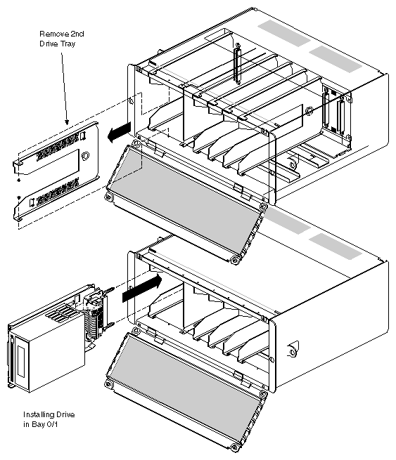
Full-height drives require two half-height drive slots. To accommodate the greater width of the full-height drive, you must remove the drive tray that separates bay 0 from bay 1 in the RAID box:
Open the front door of the RAID box.
Remove the two screws that secure the drive tray to the top and bottom of the RAID box chassis (see Figure 3-8).
Pull the drive tray out of the chassis.
Follow the drive installation instructions listed in the previous section.
Use the following procedure to power on the chassis after all installations are complete:
Plug in the power cords that feed into each component in the system. Make sure to connect the cords to properly rated grounded outlets only.
After you turn on the system power, the system begins the boot process.
Do not reboot the system during this time or you will continue to delay system initialization.
The System Controller begins the power-on sequence. As the system comes up, its progress is automatically displayed on the controller's front panel by using a series of boot messages. Pushing any of the function keys at this time will interrupt the sequence of boot messages that are appearing, see Table 3-1. Pushing a function key during the boot process may cause the following message to appear:
BOOT ARBITRATION ABORTED
Table 3-1. System Controller Boot Status Messages
Boot Status Message
Message Description
BOOT ARBITRATION NOT STARTED
The system CPU boards have not begun the arbitration process.
BOOT ARBITRATION IN PROCESS
The system CPU boards are communicating to decide which one will be the system master CPU.
BOOT ARBITRATION IS COMPLETE SLOT #0X PROC #0X
The chosen CPU master has identified itself to the Controller and communication is fully established.
BOOT ARBITRATION INCOMPLETE FAULT NO MASTER
The system was unable to assign a master CPU.
BOOT ARBITRATION ABORTED
An operator pushed one of the front panel buttons while the System Controller was searching for the master CPU.
Note: To better monitor and understand the boot process on the System Controller's front panel, see the system's installation guide or check Chapter 3 in the CHALLENGE/Onyx Diagnostic Roadmap P/N 108-7045-0x0. When the power-on diagnostic has completed, enter the PROM "Command Monitor."
The >> prompt is displayed.
Note: You should test the function of the disk-down LEDs on the drives and controller board at this point. Push the small square button at the bottom of the RAID controller board. Refer back to Figure 1-5 if you are unsure of its location. When you push this reset button, the fault cable function is tested and all the amber fault LEDs should light up. Type hinv, then press <Enter> to display the hardware inventory of your system. At the PROM level, the system will not differentiate between RAID and non-RAID SCSI drives. IRIX must be fully booted before hinv can report the drives as RAID devices.
Note: See Chapter 4 in the RAID System Administration Guide for information about configuring a new RAID disk array in the system. Quit the PROM monitor by typing Exit at the >> prompt.
The System Maintenance menu reappears. Type 1 to select the "Start System" command. The system will come up.