This chapter describes how to unpack, cable, and configure the Cardcage 2 InfiniteReality graphics upgrade for Onyx rackmount systems. The generic term Onyx is used unless there is a need to differentiate one type of system from another. InfiniteReality graphics are not supported in R8000 (IP21-based) systems.
The procedures in this chapter are written for an experienced field installer who is familiar with the rackmount Onyx system. You may wish to consult the CHALLENGE/Onyx XL Rackmount Installation Instructions (P/N 108-7042-0x0), if you need additional information. This chapter consists of the following sections:
Use the following steps as a quick installation checklist for the InfiniteReality graphics upgrade:
Read the safety precautions, then shut down the system and open the back door.
Undo the I/O panel to access the board slots in Cardcage 2.
Remove the F2-equipped IO4 board.
Remove all the graphics boards.
Remove the CC1 power boards.
Remove and replace the system midplane, if necessary (some systems are already InfiniteReality ready); see "Determining If the System Backplane Is InfiniteReality Ready" near the end of Chapter 1.
Install the InfiniteReality 303x2, 305x2, and 512Tx2 power boards.
Remove the two OLS units in the rack and replace them with 50-amp units.
Remove any mezz boards from the F2-equipped IO4.
Reinstall the mezz boards on the F3-equipped IO4 (013-1652-00x) or on another IO4 board.
Unpack the InfiniteReality upgrade boards, I/O panels, and cables.

Note: Do not reinstall non-master IO4s until after you have successfully booted the upgraded system. Install the new F3-equipped IO4 and VCAM assembly in slot 11.
Install the InfiniteReality graphics board set and all other applicable boards in the rack.
Remove and replace the main graphics I/O panel.
Connect internal cables to the graphics boards and I/O panel.
Close up and secure the I/O panel.
Connect the monitor cables.
Power on the system and verify normal operation.
Return the graphics boards and panels to Silicon Graphics.
 | Warning: Installation of this upgrade requires specific training and technical knowledge. These instructions have been provided for use by Silicon Graphics system support engineers (SSEs) or Silicon Graphics trained or certified personnel only. This equipment uses internal voltages that are hazardous if the equipment is improperly assembled or disassembled. Wait five minutes after powering off a rackmount system before working on any part of the power supply or midplane/backplane. Because of the large amount of capacitance in the system, a significant fraction of the operating voltage remains on the midplane/backplane for up to five minutes after the system is powered down. |
 | Caution: This equipment is sensitive to damage from electrostatic discharge (ESD) caused by the buildup of electrical potential on clothing and other materials. |
Follow these ESD preventive measures:
Attach a ground strap to your wrist when connecting or disconnecting boards.
Ensure that you and all electrical equipment that you handle during this installation are at ground potential to avoid damage from ESD.
Keep the boards in their antistatic bags until they are needed, and remove them only when you are properly grounded to the chassis ground.
Place the boards only on an antistatic mat. Do not place boards on top of an antistatic bag unless the outside of the bag also has antistatic protection.
Store removed boards in ESD-safe packing or storage boxes.
If you are servicing a system or installing a hardware upgrade, do not disconnect the power cord from the wall socket or the chassis. You will lose the system ground and could damage the equipment as a result.
Do not use an ohmmeter on the boards as it can damage sensitive ICs or other components.
Remove all finger, wrist, and arm jewelry before working on the system.
To successfully upgrade CC1 and 2 in the Onyx rackmount system to an InfiniteReality, you must have the parts in the following list:
CD-ROM with upgrade OS and/or patch (P/N is variable).
GE12 graphics board using GE11 geometry engines (P/N 030-0681-00x).
RM6 raster manager board with 16 MB of texture RAM (P/N 030-0683-00x) or 64 MB of texture RAM (P/N 030-0684-00x). One, two, or four RM6 boards are supported.
Replacement master IO4 with upgraded F3 ASIC (P/N 013-1652-00x).
DG4 display generator board, two channels (P/N 030-0686-00x), or the eight-channel DG4-8 board (P/N 030-0687-00x).
Internal graphics I/O interface cable for two-channel, 68-pin VIO2 board (P/N 9290129), or optional six-channel, 80-pin cable for the VIO6 I/O board (P/N 9290130).
FP1 frontplane board assembly (P/N 013-1596-00x).
InfiniteReality graphics VIO2 two-channel I/O board and panel with all graphics connectors (P/N 013-1342-00x).
303x2 power board for CC2 rackmount upgrades (P/N 030-0741-00x).
305x2 power board for CC2 rackmount upgrades (P/N 030-0743-00x).
512Tx2 power board for CC2 rackmount upgrades (P/N 030-0742-00x).
Rackmount "door strip" (P/N 024-0947-00x "generic") or (024-0963-00x "R10000").
Slot assignment label for CC2 (P/N 024-0953-00x).
Top board retainer bar for deskside systems (P/N 013-1615-00x).
Two 50-amp OLS units (P/N 013-1592-00x).
| Note: All three of the access covers to the rackmount chassis are held shut with magnetic strips; there are no latches. |
Gain access to Cardcage 2 and install the InfiniteReality graphics upgrade by following these steps:
Open the rear door of the system cabinet.
Determine if any of the cables attached to the I/O panel obstruct the panel's movement when opened. Remove cables as required.
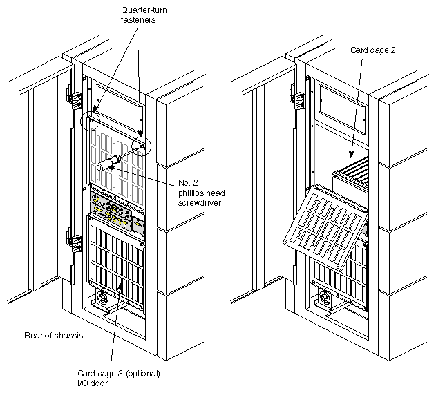
Release the two quarter-turn fasteners securing the I/O panel (see Figure 3-1) and lower the panel until it is horizontal.
Carefully remove any internal I/O cables that prevent the panel from pivoting down past horizontal.
Undo the cable supporting the I/O panel and gently allow the panel to pivot down toward the floor.
Undo the cables and remove the master IO4 board and VCAM assembly.
Note: If there is a short mezzanine board on the master IO4, it must be moved to another IO4 or to the new F3-equipped master IO4. Remove the existing RE2 slot assignment label from CC2 and replace it with the InfiniteReality slot assignment label (P/N 024-0953-00x).
Remove the GE10, DG2, and RM4 or RM5 graphics boards from Cardcage 2.
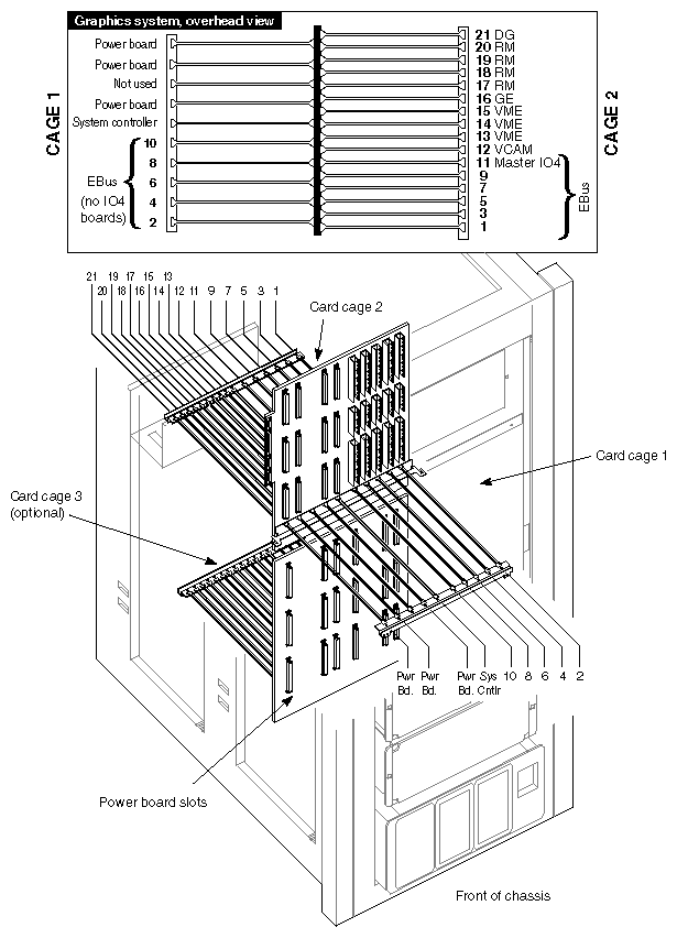
The slot assignments for the Onyx rackmount are shown in Figure 3-2. Be aware that in the field the original RE2 slot assignments (as indicated by the stick-on labels over the cardcages) are different.
In Cardcage 1, the only board with a dedicated slot is the System Controller power board. This restriction is due to the System Controller board's unique backplane connectors. There are no restrictions on any of the CC1 Ebus slots; CPUs and memory boards can be installed in any order. IO4 boards are not used in CC1.
In Cardcage 2, the only Ebus board having a dedicated slot is the master IO4 board. The first (or only) IO4 board must be installed in slot 11, with its mounted VCAM attached to the slot 12 backplane connectors. Additional IO4s (with no VCAMs) can be installed sequentially in slots 9 (second IO4), 7 (third IO4), and 5 (fourth IO4).
At this point you must determine if the Onyx system you are upgrading was shipped with an InfiniteReality ready midplane. If it was, then skip the following subsection and go directly to "Installing the InfiniteReality Graphics Boards."
Determine if the system is equipped with an InfiniteReality ready midplane by confirming the criteria listed in "Determining If the System Backplane Is InfiniteReality Ready." This section is located near the end of Chapter 1.
If the system is not equipped with a InfiniteReality ready midplane, then you must install the new midplane using the instructions in the next section.
This procedure describes how to remove and replace the system midplane.
Confirm that the system has been powered down for more than five minutes.
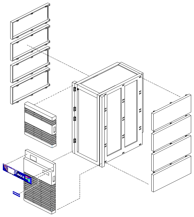
Remove the side panels from both sides of the cabinet by starting with one of the top panels. Grasp the panel with both hands through the access hole at the rear of the panel (see Figure 3-3).
While keeping your foot braced against the bottom of the chassis, tug backwards sharply on the side panel. It should pull free. If it does not, tug slightly harder. Be careful not to tip the chassis or strain your back.
Repeat this procedure for each of the eight panels (four per side of the chassis).
Working at the left side of the cabinet (as seen from the front of the system), unfasten the four cables attached to the midplane connectors (see Figure 3-4).
Access Cardcage 1 and 2, and remove all the boards from both cardcages.
Note: Remove the blower assembly to allow easier access to the upper card guide of either cardcage (see Figure 3-5 for an example). Working from the front of the cabinet, unfasten the two screws securing the upper card guides. Note that the guide assembly is positioned in the cardcage by four tabs that fit into four corresponding slots in the sides of the cardcage. Gently pull the guide assembly toward the front of the cabinet and away from the midplane. You may find it easier to manipulate the card guide if you remove the blower assembly. Removing the blower assembly allows better access to the upper card guide.
Caution: Do not allow the rear of the guide assembly to drop out of the two rear locating slots. If the rear of the guide assembly drops, it will contact the midplane and possibly damage it. Repeat the previous step for the bottom card guide assembly, and for the top and bottom card guides in the rear cardcage.
Remove the side panel SCSIBox cover plate and connection, then carefully remove the SCSIBox(es) from the cabinet, see Figure 3-6.
Remove the access panel that isolates the SCSIBox enclosure from the midplane jumper board. The access panel is positioned by two alignment pins at its top edge and secured by four quarter-turn screws.
Note: The quarter-turn screws used with the access panel are not spring-loaded like the ones used with the I/O panels and do not release positively when turned. You must turn each one back and forth slightly while pulling gently on the corner it secures in order to release it.
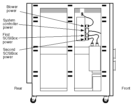
Working from inside the SCSIBox enclosure, unfasten the five power connectors at the lower edge of the midplane.
Verify that all of the connections to the midplane have been removed.
Loosen the ten screws securing the midplane access port cover on the right side of the cabinet. Lift the cover slightly and remove it from the cabinet.
Use a 3/32-inch hex (Allen) wrench to loosen the upper and lower wedgelocks (located at the top and bottom edges of the midplane).
Carefully slide the midplane out of the cabinet.
Caution: If you feel resistance, stop immediately and determine its cause. Verify that the card guides have been withdrawn from the midplane enough to give sufficient clearance.
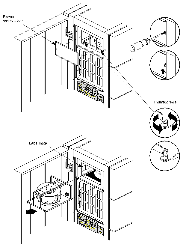
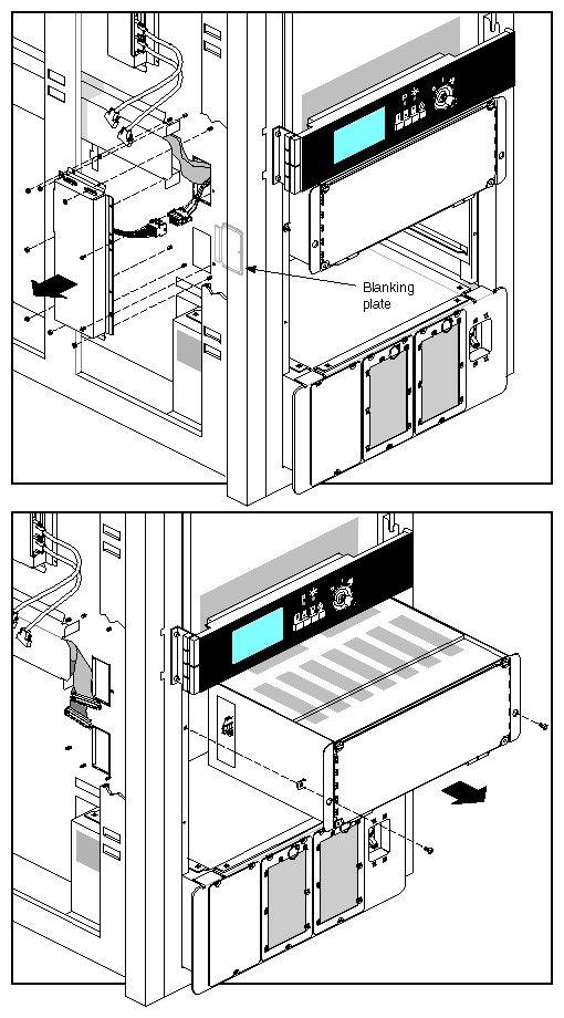
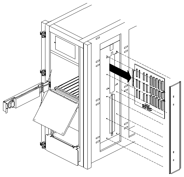
Reverse this procedure to install the InfiniteReality midplane.
The InfiniteReality graphics systems use more power than RE2. Each OLS used with RE2 rack systems produces approximately 40 amps of 48-V power for the system. InfiniteReality systems must use the newer 50-amp OLS units. The units are nearly identical. To tell them apart, look for stickers or tags identifying the 50-amp OLS. You must replace 40-amp units with 50-amp units during the InfiniteReality upgrade process.
With the lower front access door open, the two system OLS units are easy to access.
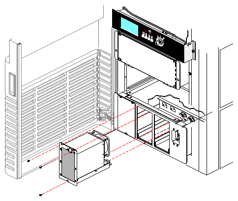
Remove the three screws securing each 40-amp OLS that you want to remove (see Figure 3-8).
Grasp the 40-amp OLS by the ring in the upper right corner, and pull it from the power supply enclosure.
Repeat steps 1 and 2 as necessary.
Install a 50-amp OLS by reversing the steps in this procedure. Ensure that the connector at the rear of the OLS mates correctly with the corresponding connector in the power supply enclosure.
The InfiniteReality ready midplane uses new x2 power boards that produce 3.45 volts, or a combination of 3.45 volts and 5 volts. These power boards are basically twice the size and output of the regular power boards. They are generically known as the 303x2 and 305x2. There is also a new 512Tx2 board. Even if you did not install a new backplane, you must install the new power boards to properly complete an InfiniteReality upgrade.
The non InfiniteReality graphics backplane employs two 505x2 power boards, one 512x2 board, and one System Controller board. Figure 3-9 shows the locations of the power boards as well as the graphics and other boards. The 505 board provides 5 volts for use by the boards. The 512 provides both 5 volts and 12 volts. The 12-volt supply gives power to the drives and VME.
| Note: The old 512 power board does not supply the same power levels as the newer 512T and should not be installed when a 512T is called for. |
The System Controller board provides 1.5 VDC for the Everest bus and also provides power for the system controller. This board can plug only in the rightmost power-board slot because the connectors are different from the other power boards. Refer to Figure 3-9 if you are unfamiliar with the proper CC1 power board locations.
Install the power boards in the InfiniteReality ready midplane by following these steps:
If you removed a non InfiniteReality backplane from the system, locate the System Controller board that was removed from the system.
Install the System Controller board in the rightmost power board slot on the CC1 side of the InfiniteReality midplane. The other power boards can install in any slot.
Install the 305x2 power board (P/N 030-0743-00x) in any available power board slot.
Install the 303x2 power board (P/N 030-0741-00x) in any available power board slot. Note that the 303x2 board requires more force to properly seat because of the large 3.45-V power pins.
Install the 512Tx2 power board (P/N 030-0742-00x) in the remaining power board slot.
Note: At this juncture you should stop and take a 3-V power reading on the new InfiniteReality backplane to confirm functionality. Section 1.12, "Checking 3-Volt Power on the InfiniteReality Backplane" in Chapter 1 provides information and procedural steps to accomplish this. Confirm that all boards are properly seated and electrical connections properly made.
Note that the new F3-equipped IO4 and VCAM assembly always goes in slot 11 of Cardcage 2. Additional non-master I04s that were previously installed can be removed from the chassis during the initial boot of the system.
It is probable that they will need a PROM code update to work properly in the upgraded system. See Appendix A, Section A.2.4, "Flashing an IO4 Through the Command Monitor (flash -T)" if you need additional information on this topic.
After you have reinstalled the CPU(s) and memory board(s), use the following information to install the InfiniteReality graphics boards, IO4, FP1 frontplane, and I/O panel:
Install the InfiniteReality graphics boards according to the patterns shown in Figure 3-9.
Place baffle boards in any empty slots after all existing and new boards are installed in CC2.
After reinstalling the CPU, memory, or new F3-equipped IO4 boards, replace the top board retainer bar with the InfiniteReality version (P/N 013-1623-00x).
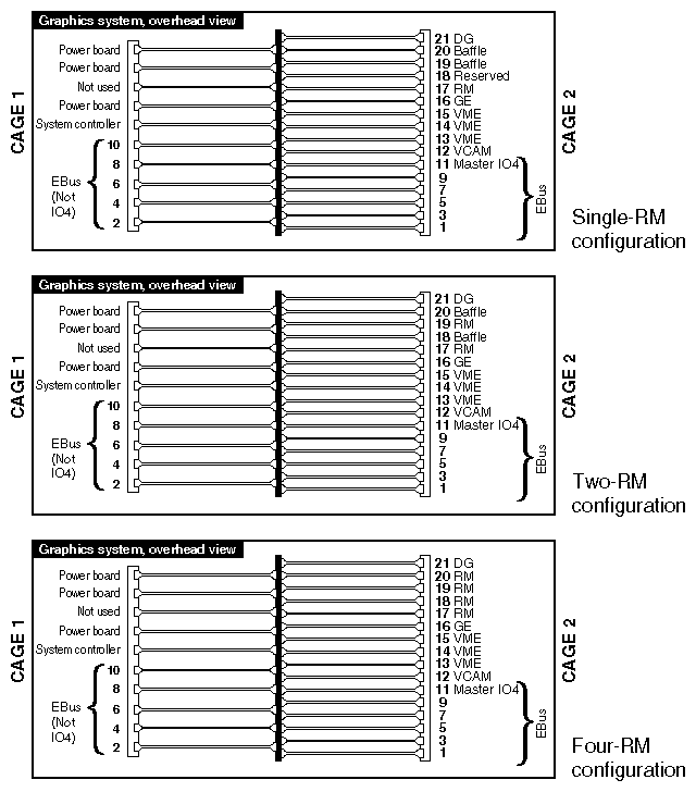
| Note: Never install RM6 boards in the same pipe that have different amounts of TRAM on board. There is an RM6 with 16 MB of texture RAM (P/N 030-0683-00x), and a version with 64 MB of texture RAM (P/N 030-0684-00x). Each InfiniteReality CC2 can support one, two, or four RM6 boards. See Chapter 1 for more technical detail on the RM6 boards. |
Install the new InfiniteReality video I/O panel, FP1 frontplane, and video cable(s), as shown in Figure 3-10. Use extra care when aligning the FP1 pins to the installed boards.
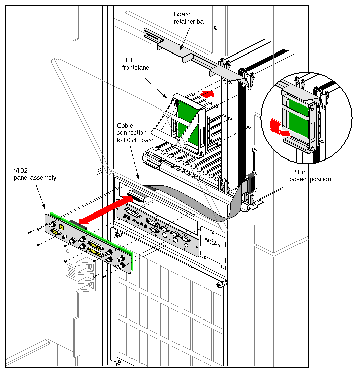
| Note: If the upgrade was ordered with the optional DG4-8 and VIO6 panel assembly, install them using the following steps; otherwise, go to the next section. |
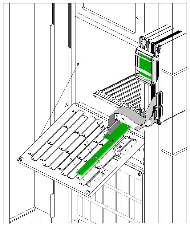
Install the optional VIO6 panel assembly by removing four I/O connector plates and replacing them with the assembly (see Figure 3-11 for an example).
Connect one end of the optional 80-pin VIO6 cable to the DG4-8 and the other end to the VIO6 panel connector.
Always close the I/O panel door carefully to avoid damage to the 80-pin cable or other cables present.
Card cage 2 has three available VME slots and supplies approximately 40 watts of +5-VDC power per VME slot (nominally) and also receives approximately 200 to 250 linear feet per minute (LFM) of air flow.
When using an InfiniteReality rackmount system with large numbers of processor, memory, graphics, and I/O boards, system power availability may limit the number of VME boards you can install. Table 3-1 gives examples of the number of VME boards usable in CC1 and CC2 maximum configuration InfiniteReality systems. Also, use the following basic exchange rules if you want to add or remove VME or other boards to a maximum configuration system:
One VO2 (Sirius) board = two VME boards
One CPU board = one memory board and one IO4 board
| Note: There are no VME slots in the card cage 1 in Onyx rackmount systems. |
Table 3-1. CC1 and CC2 InfiniteReality Maximum Configuration Examples
CPU Bds. | Memory Bds. | IO4 Bds. | RM Bds. | VO2 Bds. | VME Bds. |
|---|---|---|---|---|---|
6 | 2 | 1 | 4 | 2 | 1 |
6 | 4 | 1 | 2 | 2 | 1 |
6 | 4 | 1 | 4 | 1 | 0 |
5 | 3 | 2 | 4 | 2 | 1 |
5 | 2 | 3 | 4 | 2 | 1 |
5 | 4 | 1 | 4 | 2 | 1 |
4 | 2 | 4 | 4 | 2 | 1 |
Note that the InfiniteReality graphics upgrade does not automatically ship with a color monitor (monitors are listed as separate line items from the InfiniteReality upgrade bundle). Regardless of the monitor's origin, it must use a 13W3 connector. Refer to the end of Chapter 2 for an example of a 21-inch graphics monitor.
| Note: For additional information regarding monitor operation, see the user's guide for the monitor. |
Connect the color monitor to the 13W3 connector by following these steps:
Find the monitor video cable. It has large 13W3 connectors on each end.
Attach one end of the monitor video cable to the 13W3 connector on the back of the monitor. Secure the screws on either side of the connector.
Attach the other end of the monitor video cable to the 13W3 connector on the system's I/O panel. Secure the screws on either side of the connector.
See Chapter 1 for the VIO2 13W3 pinouts and all VIO6 13W3 connectors. The Stereoview and S-video connector pinouts are also shown.
For information on system software, power-on, and diagnostics, see Appendix A.