This chapter describes how to upgrade an Onyx rackmount system with a Cardcage 3 and the new InfiniteReality graphics boards. All the graphics pipes in the rack system must be InfiniteReality. You cannot have a VTX or RE2 graphics pipe in CC2 of the rackmount and an InfiniteReality pipe(s) in CC3. This chapter is made up of the following sections:
Use the following steps as a quick checklist for the Cardcage 3 InfiniteReality Graphics upgrade:
Read the safety precautions.
Shut down the system.
Take off the side panels and open the access to the backplane.
Install an FCI-equipped IO4 (with F3) in Cardcage 2 (one for each pipe).
Remove the side panels, access doors, SCSI box, and OLS cover.
Remove the plate covering the midplane power connectors and unplug them all.
Remove the old OLS units and OLS tray and the power cable.
Install the new tray and the 50-amp OLS units.
Install the new cage and backplane (note that previously installed CC3s may already have an InfiniteReality ready backplane).
Install the remote VCAM and cables.
Unpack the InfiniteReality boards and cables.
Install the new power boards into the InfiniteReality backplane.
Install the InfiniteReality graphics board set and air baffle boards.
Connect the internal cable to the graphics board and I/O plate.
Power on the system and verify normal operation.

Note: Using InfiniteReality CC3 graphics pipes with an RE2 or VTX pipe in CC2 is an unsupported configuration.
Read these safety statements carefully before you remove or install any components.
 | Warning: Installation of this upgrade requires specific training and technical knowledge. These instructions have been provided for use by Silicon Graphics system support engineers (SSEs) and Silicon Graphics trained or approved personnel only. This equipment uses electrical power internally that is hazardous if the equipment is improperly assembled or disassembled. Wait 5 minutes after powering off a rackmount system before working on any part of the power supply or midplane/backplane. Because of the large amount of capacitance in the system, a significant fraction of the operating voltage remains on the midplane/backplane for up to 5 minutes after the system is powered down. |
 | Caution: This equipment is sensitive to damage from electrostatic discharge (ESD) caused by the buildup of electrical potential on clothing and other materials. |
Follow these ESD preventive measures:
Attach a ground strap to your wrist when connecting/disconnecting boards.
Ensure that you and all electrical equipment that you handle during this installation are at ground potential to avoid damage from ESD.
Keep the boards in their antistatic bags until they are needed, and remove them only when you are properly grounded to the chassis ground.
Place the boards only on an antistatic mat. Do not place boards on top of an antistatic bag unless the outside of the bag also has antistatic protection.
Store all removed boards in antistatic bags or protective boxes.
If you are servicing a system or installing a hardware upgrade, make sure that you and the system chassis are at the same ground potential. When servicing or upgrading the OLS tray, find an alternate ground source.
Do not use an ohmmeter on the boards as it can damage sensitive ICs or other components.
Remove all finger, wrist, and arm jewelry before working on the system.
The InfiniteReality card cage 3 (CC3), uses different power boards and has limitations different from the RE2 CC3 version.
| Note: Each remote VCAM in the CC3 is only capable of supplying a maximum of 1 Amp of current in the -12 V and -5 V ranges. This may limit or restrict the number and/or type of VME boards installed in each CC3 VMEbus bank. |
The Infinite Reality graphics board set consumes more power than the RE2 board set. It obtains nearly all of its power from the 3.45-V power boards. A maximum graphics configuration with two pipes and four RMs per pipe requires five 3.45-V power boards.
This allows only one other power board in the CC3, a single 512T board which provides all of the available 5-V and 12-V VME power. This limits the power available for VME.
Table 4-1 shows the total available power for all VME boards in the CC3.
Table 4-1. InfiniteReality CC3 VME Power Availability
CC3 Power Boards | +5V VME Power Available | +12V VME Power Available |
|---|---|---|
Five 303s and one 512T | 50 amps (250 watts) | 15 amps (180 watts) |
Note that with only 250 total watts of (+5 V) VME power available, you can install a very limited number of VME boards in a fully loaded CC3.
Because the InfiniteReality graphics boards use more power than the RE2 boards, you must upgrade the rack with three 50-amp OLS units. This provides more power to the system, but system configuration limits are still neccesary. These "total system power" limits must be considered in addition to the limitations specific to CC3 VME boards as described in the previous section. Graphics or VME malfunctions may occur if the power capacity of the system or the CC3 is overtaxed.
The following four tables describe limitations on maximum board configurations in CC3 rack systems. The VME board limits in these tables are for all VME boards in the system, both CC2 and CC3. System configuration outside these limits must be balanced by removal of a board or boards requiring equal power. Use the following rules to make trade-offs:
one memory board and one IO4 board = one CPU board
one VO2 (Sirius) board = two VME boards
Table 4-2 shows the limits of a fully configured InfiniteReality system using three graphics pipes with four RM6s in each pipe. The power for a standard VME board is calculated as 40 watts.
Table 4-2. System Maximum (12 RM6s) Board Configuration
CPU Bds. | Memory Bds. | IO4 Bds. | RM Bds. | VO2 Bds. | VME Bds. |
|---|---|---|---|---|---|
4 | 4 | 3 | 12 | 0 | 0 |
3 | 4 | 3 | 12 | 1 | 0 |
3 | 2 | 3 | 12 | 2 | 1 |
2 | 2 | 3 | 12 | 3 | 0 |
Table 4-3 shows the limits of an InfiniteReality system using three graphics pipes, with four RM6s in two pipes, and two RM6s in the third pipe.
Table 4-3. System Maximum (10 RM6s) Board Configuration
CPU Bds. | Memory Bds. | IO4 Bds. | RM Bds. | VO2 Bds. | VME Bds. |
|---|---|---|---|---|---|
6 | 2 | 3 | 10 | 4 | 2 |
5 | 2 | 3 | 10 | 3 | 0 |
4 | 1 | 3 | 10 | 4 | 2 |
Table 4-4 shows the limits of an InfiniteReality system using three graphics pipes, with four RM6s in one pipe and two RM6s in the second and third pipes. Note that some configurations shown in the tables may require a 305 power board upgrade in CC3 to successfully support the large numbers of VO2 and VME boards listed in the examples.
Table 4-4. System Maximum (8 RM6s) Board Configuration
CPU Bds. | Memory Bds. | IO4 Bds. | RM Bds. | VO2 Bds. | VME Bds. |
|---|---|---|---|---|---|
6 | 2 | 3 | 8 | 4 | 2 |
5 | 2 | 3 | 8 | 5 | 2 |
4 | 2 | 3 | 8 | 6 | 2 |
Table 4-5 shows the limits of an InfiniteReality system using two graphics pipes, with four RM6s in each pipe.
Table 4-5. Two-Pipe System Maximum (8 RM6s) Board Configuration
CPU Bds. | Memory Bds. | IO4 Bds. | RM Bds. | VO2 Bds. | VME Bds. |
|---|---|---|---|---|---|
6 | 2 | 3 | 8 | 4 | 3 |
5 | 4 | 2 | 8 | 4 | 4 |
Before beginning the installation procedure, verify that all of the necessary parts are present. See the following parts list(s). The RealityEngine2 to InfiniteReality upgrade kit should include the items listed (unless a CC3 is already installed). Note that the rack-mounted InfiniteReality Cardcage 3 graphics system can contain up to two graphics pipes. Each of these pipes can use up to four RM6 boards. There are restrictions on the number of boards supported in each CC3 graphics application. Section 4.3, "InfiniteReality Cardcage 3 and System Power VME Guidelines," provides information on board usage and power available in maximum configurations.
The hardware upgrade kit contents should include
3-Phase offline switcher (OLS) tray (P/N 013-0513-00x) (when installing a new CC3)
3-Phase 50-amp offline switchers (Quantity 3) (P/N 013-1592-00x)
Cardcage 3 top card guide for graphics (P/N 013-0536-00x) (when installing a new CC3)
Cardcage 3 bottom card guide for graphics (P/N 042-0151-00x) (when installing a new CC3)
Cardcage 3 graphics I/O door panel (P/N 013-0832-00x) (when installing a new CC3)
Cardcage 3 board locking assembly (Top) (P/N 013-1623-00x)
Cardcage 3 board locking assembly (Bottom) (P/N 013-0537-00x)
Cardcage 3 InfiniteReality ready graphics backplane (P/N 030-0557-00x)
five 303 power boards (P/N 030-0677-00x)
one 512T power board (P/N 030-0739-00x)
remote VCAMs (P/N 030-0502-00x) (not needed when upgrading an existing CC3 graphics cardcage)
graphics system air deflector (P/N 013-0853-00x) (not needed when upgrading an existing graphics CC3)
jumper wire assembly (P/N 015-0133-00x)
OLS air cover (P/N 040-0750-00x)
Cardcage 3 graphics slot labels for InfiniteReality (P/N 024-0954-00x)
60-pin micro-strip cables (P/N 9290049)
North American 220-V 3-phase label (P/N 024-0635-00x)
international 400-V 3-phase label (P/N 024-0636-00x)
Cardcage 3 interrupt board (P/N 030-0516-00x)
F3-equipped non-master IO4 board assembly with F3-mezz daughter board (P/N 030-0815-00x) (one per pipe)
two 1900-RPM rotary fan assemblies (P/N 013-1650-00x)
This section describes the installation of the Cardcage 3 card guides and backplane, as well as the three-phase power supply tray.
Shut the system down and allow power to drain five minutes before starting with the upgrade.
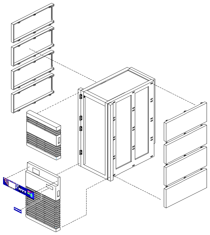
Remove the side panels from both sides of the system cabinet (four panels per side) by sliding them toward the rear of the cabinet and then lifting them off (see Figure 4-1).
Note: To avoid marring the panels, be careful when removing and storing them. Open the lower access door covering the rear of the Cardcage 3 enclosure by releasing the two quarter-turn screws located at the door's upper right and left corners.
Unfasten the screws securing the door hinge to the system chassis and remove the door.
| Warning: Avoid potential head injury during this upgrade. Make sure that the swing-down metal I/O panels that cover Cardcage 1 and 2 are always firmly secure. Screw in both locking screws when closing the cover(s). |
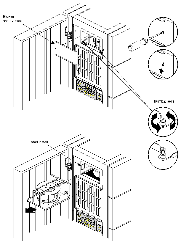
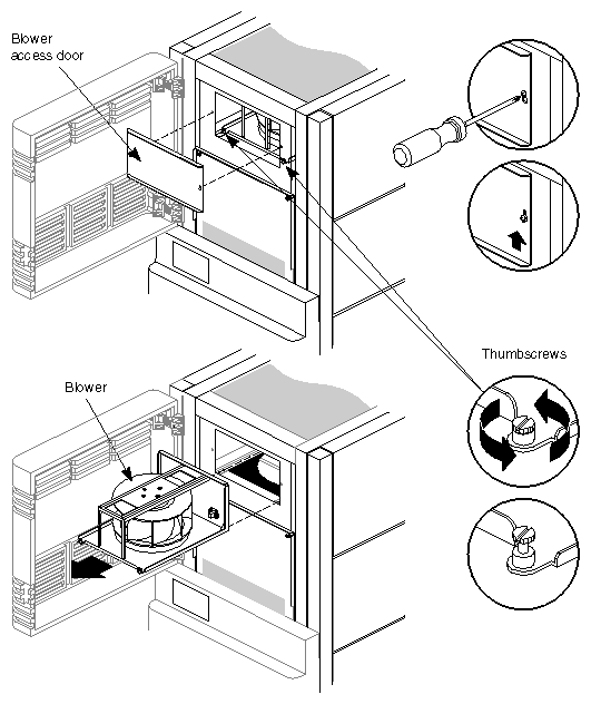
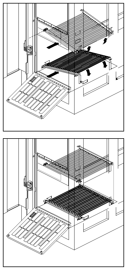
Replace the two blowers that sit above Cardcage 1 and 2 with the higher (approximately 1900-RPM) units shipped with the upgrade (P/N 013-1650-00x). Tighten all screws with a screwdriver. See Figure 4-2 and Figure 4-3 for examples.
Note: Always apply any identifying labels accompanying the new blowers.
Loosen the ten screws securing the midplane and Cardcage 3 backplane access port cover to the right side of the cabinet. Lift the cover slightly and remove it from the cabinet.
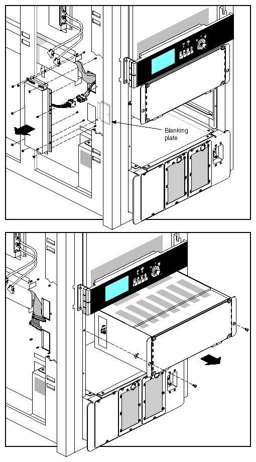
Remove the side panel SCSIBox cover plate and connection, then carefully remove the SCSIBox(es) from the cabinet. See Figure 4-4 for an example.
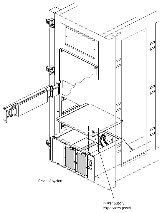
Remove the access panel from the top of the installed power supply tray by unfastening the two screws (see Figure 4-5).
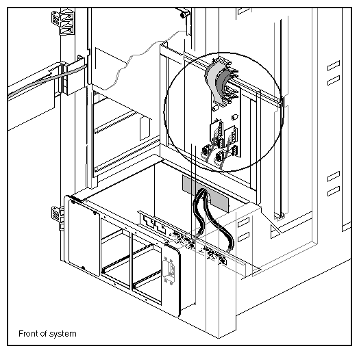
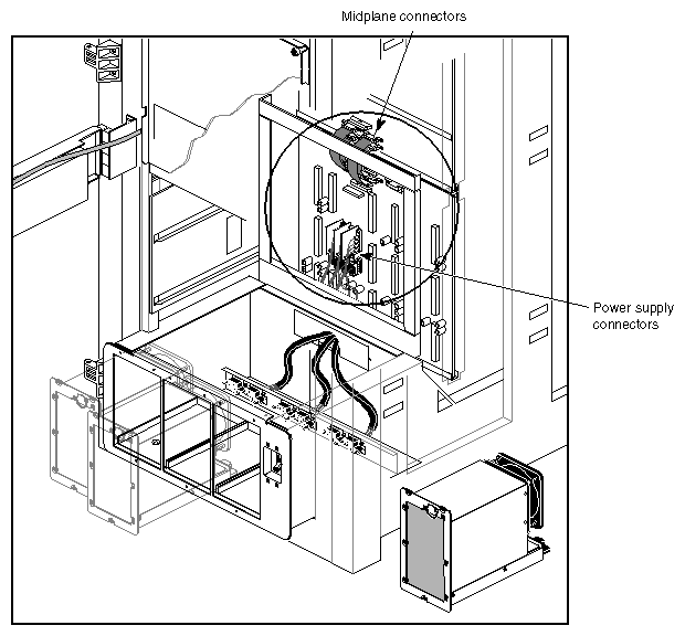
Remove the access panel that isolates the SCSIBox enclosure from the midplane jumper board or existing backplane (see the circled area in Figure 4-6).
Note: If the system already has the CC3 installed, you should confirm if it is an InfiniteReality ready backplane by reading Section 1.11, "Determining If the System Backplane Is InfiniteReality Ready," near the end of Chapter 1. If there is an IR ready backplane already installed in the rack, skip to step 12. Unfasten the five connectors at the top of the jumper board (or non IR backplane) from the upper midplane.
Unplug the four lower connectors that come from the power supply tray and connect to the jumper board or non IR backplane (see Figure 4-6).
Remove all of the OLS units installed in the power supply tray (three screws per OLS). If the rack already has a CC3 and 3-phase power tray, skip to step 20 and install the new 50-amp OLS units.
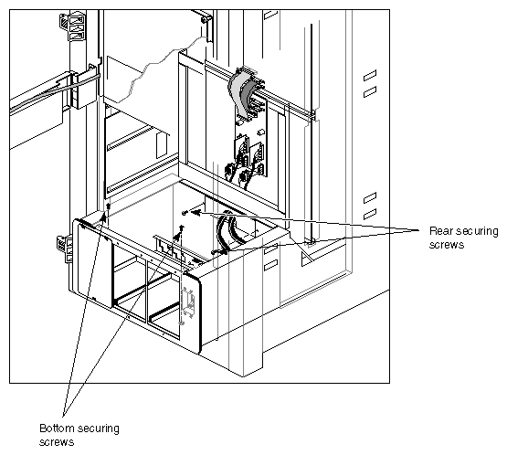
Locate and remove the four screws (two at the rear and two at the bottom) securing the power supply tray to the system cabinet (see Figure 4-7).
Disconnect and pull the four power supply cables (two bundles) back through the cable port and into the power supply tray.
Withdraw the power supply tray from the front of the system cabinet (see Figure 4-7).
Remove all OLSs and the access cover from the top of the new three-phase power supply tray that is part of the upgrade package.
Push the new power cable toward back of the rack and slide the new three-phase power supply tray into the front of the cabinet. Ensure that the rear of the tray engages the rails mounted to the floor of the cabinet.
Route the three power cable bundles through the tray's rear opening, then install the bulkhead cover using two screws.
Secure the tray's bottom to the system cabinet using the two screws you removed from the original two-phase power tray.
Install and secure the three new 50-amp OLS units in the power supply tray.
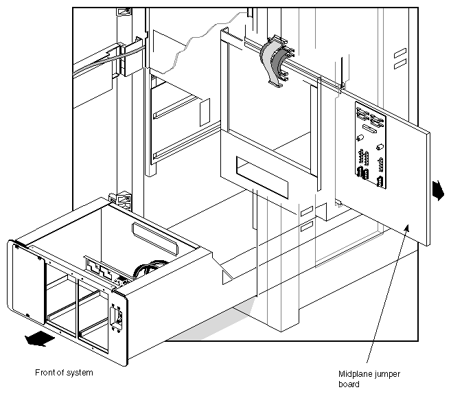
Note: Skip forward to step 30 if the system already has an IR ready CC3 backplane and cardcage installed. Withdraw the midplane jumper board or non IR backplane through the access port on the right side of the cabinet (see Figure 4-8).
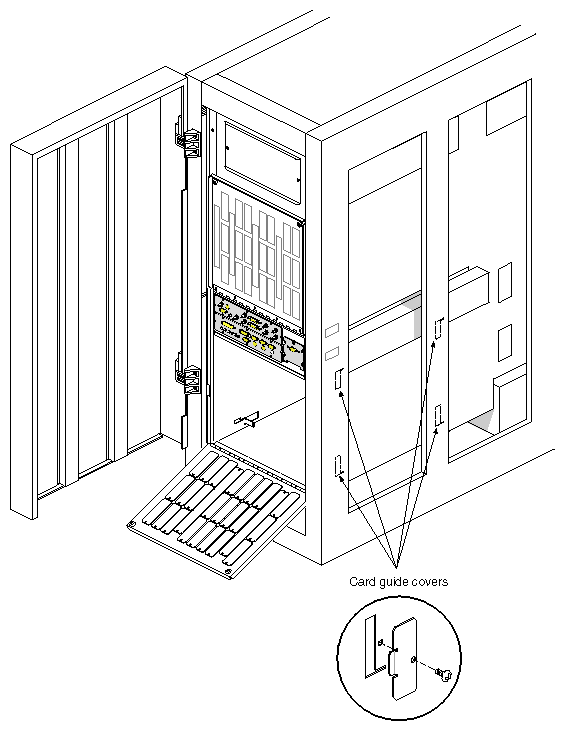
Note: If you are removing a jumper board, it is held in position by friction. There is no mounting hardware. Remove the four card guide covers from the left side of the cabinet. Each cover is mounted with a single screw (see Figure 4-9).
Note: On some systems, the card guide covers are equipped with copper EMI gaskets. Be sure to reinstall them along with the card guide covers.
Install the upper and lower Cardcage 3 card guides. Each card guide has four locating tabs (one in each corner). Make sure the tabs are perpendicular to the flange. The tabs fit into slots in the sides of the system chassis (see Figure 4-10).
Tip each guide so that the left-hand locating tabs (as seen from the rear of the system) engage the small slots in the left side of the chassis first. Insert the right-hand tabs into the larger openings on the right side of the chassis. Lower or raise the right side until the card guide is level. Then position each guide back as far as it will go in the locating slots.
Loosely reinstall the four card guide covers on the left side of the cabinet. This allows stability and flexibility for the card guides while the backplane is installed.
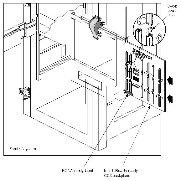
Slide the new IR Cardcage 3 backplane into the system chassis (see Figure 4-11). Feed the top and bottom wedgelocks into the U-shaped mounting tracks a section at a time, until the two locating pins on the backplane's left side engage the corresponding holes in the side of the system cabinet. Verify that the two locating pins on the right side of the Cardcage 3 backplane align with and fit through the slots in the sheet metal access cover.
Slide the top and bottom card guides forward until the guide's locating pins have mated with the corresponding holes in the new backplane. Tighten the four screws that hold the card guides in place.
Use a 3/32-inch hex (allen) wrench to tighten the wedgelocks located at the top and bottom corners of the backplane.
Tighten the card guide covers.
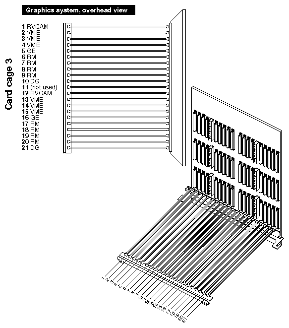
Attach the five connectors from the midplane and the six connectors from the new power supply tray to the IR Cardcage 3 backplane, as shown in Figure 4-12.
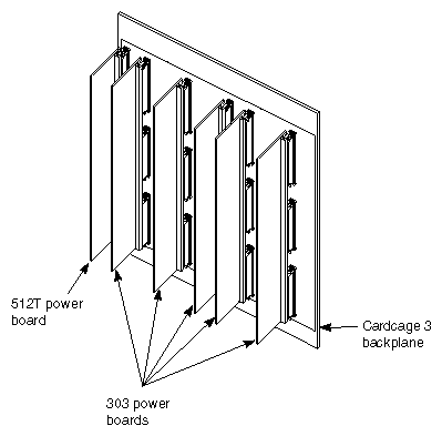
Install the new power boards in the Cardcage 3 backplane. See Figure 4-13 for an example. Because of clearance restrictions, you cannot use "double-size" (2x) power boards with Cardcage 3. The 303 power boards require more effort to seat properly than other types.
Note: The System Controller does not monitor the voltage levels on the CC3 backplane. At this juncture you should stop and manually check the +3.45, +5, -5 and -12 volt power readings on the new InfiniteReality backplane to confirm functionality. They should all measure at +/- 5% tolerance. Section 1.12, "Checking 3-Volt Power on the InfiniteReality Backplane" in Chapter 1 provides helpful information on this topic. Check your back for dirt and dust after installing the new power boards.
Install the graphics version power boards access panel. Verify that the two pins on the right side of the backplane engage the two corresponding slots in the cover. Tighten the screws that secure the power-board access cover.
Reinstall the SCSIBox(es) and reconnect the rear cable(s). Secure all screws.
Install the InfiniteReality graphics boards (see Figure 4-14), remote VCAM(s), and any other boards in the cardcage. Be sure to fill any two adjacent unused slots with a baffle board.
Caution: InfiniteReality rackmount systems with a Cardcage 3 upgrade require an additional, dedicated IO4 board with each graphics pipe. Each dedicated IO4 has a long mezz board mounted in the bottom position where the F3 controller is located. An InfiniteReality graphics pipe will not run if connected to an F2 mezz board in the top position.
Mount the long F mezz card to the bottom of the IO4 board that came as part of the Cardcage 3 upgrade. Use the standoffs and mounting hardware provided.
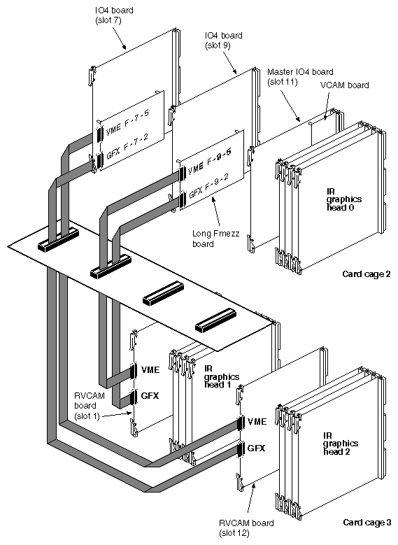
If the IO4 board that came as part of the Cardcage 3 upgrade will be the second IO4 in the system, install it in slot 9. If it will be the third IO4, install it in slot 7. The connection example shown in Figure 4-15 presumes that the installation starts in
slot 9. Note that the IO4 board must be equipped with the F3 ASIC (assembly 030-0815-001) or later.Caution: The cabling connections from the IO4's F mezz to the remote VCAM are exactly the opposite of those used in RE2. Use the cabling procedure as shown in Figure 4-15, or the InfiniteReality graphics will not function.
In configurations where a single graphics pipe (board set) will occupy Cardcage 3, connect the F mezz to the remote VCAM board in Slot 1. If the configuration calls for a second graphics pipe in Cardcage 3, install the second Remote VCAM in Slot 12.
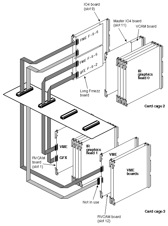
Note: In the case of a two-pipe system, place the graphics pipe in the left side of the CC3 enclosure. Use an F mezz board plugged into the top position on the IO4 to support only VME boards in the right-hand side of CC3 (see Figure 4-16). See Section 4.3, "InfiniteReality Cardcage 3 and System Power VME Guidelines," before installing VME boards in the CC3. Attach the ribbon cables to the IO4 board connectors as shown. Route each cable from CC2 down through the cable ports immediately behind the main I/O panel. Attach the remaining end of each cable to the corresponding connector on the remote VCAM.
Note: All cables are the 60-pin micro-strip cable (P/N 9290049). The I/O adapter labeling for each FCI connector changes with the location of the F mezz cards. Ensure that F mezz cards are installed in the locations shown. Install the top and bottom board lock assemblies and the FP1 frontplane(s).
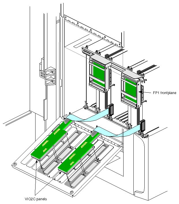
Install the VIO2C I/O panel(s) (see Figure 4-17 for an example).
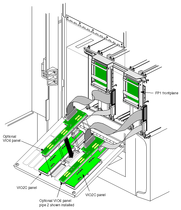
If you need to install the optional VIO6 assembly panel(s), see Figure 4-18.
Reinstall the access covers.
When the third cardcage (Cardcage 3) is populated with InfiniteReality graphics boards, a combination of system boards must be installed. These boards include
a second F3-equipped IO4 board in Cardcage 2 (one for each pipe)
long F mezz boards
remote VCAMs in Cardcage 3 (one per pipe)
Also, in order to use some of the additional I/O capabilities (such as additional Ethernet ports or serial ports), some system configuration is required. See the system(4) reference (man) page. Check the information in Section 4.3, "InfiniteReality Cardcage 3 and System Power VME Guidelines," before installing any optional VME boards in CC3.
See Chapter 3 if you need general information on monitor connections.
See Chapter 1 for 13W3 pinouts on the VIO2, and all VIO6 13W3 monitor connectors. The Stereoview and S-video connector pinouts are also shown.
For information on system power-on and diagnostics, see Appendix A.
Continue to the next section and ensure that all system power and ground requirements are met.
The following sections define the power, ground, and electrical outlet connection requirements for both North American and international versions of the Onyx rack.
All three-phase, four-wire versions of the Onyx rack products (CMN A010D) must be connected to electrical outlets rated as follows:
Nema L15-30R
187-264 V (208 V nominal)
30 amps
50 or 60 Hz
The socket outlet should be installed near the equipment and should be easily accessible.
All North American three-phase, four-wire versions of the Onyx rack products (CMN A010D) must meet the following specifications:
An insulating grounding conductor must be installed that is identical in size, insulation material, and thickness to the grounded and ungrounded branch circuit supply conductors.
It must be green and may or may not have yellow stripes.
The conductor must be installed as part of the branch circuit that supplies the unit or system.
The grounding conductor must be connected to ground at the service equipment or, if supplied by a separately derived system, at the supply transformer or motor-generator set.
The attachment-plug receptacles in the vicinity of the system must all be the grounding type and the grounding conductors serving the receptacles must be connected to the ground at the service equipment.
All 3-phase, 5-wire, European type "WYE" versions of the Onyx rack products (CMN A010Y) must be connected to electrical outlets rated as follows:
3/N/PE
AC 360-480 V
30 amps minimum
50 or 60 Hz
All three-phase, five-wire European type "WYE" versions of the Onyx rack products (CMN A010Y) must meet the following specifications:
The electrical outlet to which the system is connected must be a three-phase, five-wire, "WYE" connection with both neutral and earth ground terminals as well as terminals for each of the three-phase conductors.
The integrity of the neutral connection must be verified to avoid OLS damage.
For connection to "IT" power systems, a four-pole breaker must be available at the building site.
Included in the Cardcage 3 upgrade kit is a label that must be applied over the "MODEL NO:" section of the original system serial number label. This label was applied to the unit at the factory and is similar to: P/N 024-0603-001.
The label is located on the sheet metal base of the chassis, and is directly above the front right caster. It is visible when standing in front of the rack with the door open. Follow these steps to properly apply the regulatory labels:
Apply the new model number label so that it completely covers the original model number.
Apply the system rating label. It must be positioned on the lower right-hand corner of the system serial number label. This label should overlap the edges of the system label in order to avoid covering up any of the certification symbols.
Note: These labels must be applied to all systems that receive the Cardcage 3 upgrade in the field. They are required by regulatory and safety organizations for the installation of Cardcage 3.