This chapter describes how to unpack, install, cable, and configure the InfiniteReality graphics option for Onyx deskside systems. These instructions are written for trained service personnel, and presume the installer has some previous experience with Onyx deskside systems. InfiniteReality graphics are not supported in R8000 (IP21-based) systems.
This chapter is made up of the following sections:
Use the following steps as a quick installation checklist for the InfiniteReality graphics upgrade:
Read the safety and ESD precautions in the next section.
Shut down the system.
Open the I/O panel to access the board slots.
Remove the existing IO4 board and detach any mezz boards.
Unpack the new IO4 and VCAM assembly, InfiniteReality graphics boards, 50-amp OLS, SCSI fan assembly, backplane (if applicable), panels, and cables.
Reinstall the mezz boards on the new F3-equipped IO4 board.
Remove the existing graphics board set, frontplane, and I/O panel and replace the "SCSI stack" 5-inch fan assembly.
Partially remove the memory and CPU boards.
Remove the existing backplane (if necessary) and replace it with an "InfiniteReality ready" backplane. The InfiniteReality backplane should have yellow silkscreen and be marked "KONA Ready."
Install the new InfiniteReality power boards in the system backplane.
Install the new VIO2 (IR) graphics panel (you may also need to install the optional VIO6 graphics panel, if applicable).
Remove the old 40-amp OLS and replace it with the new 50-amp OLS.
Install the new F3-equipped IO4, GE12, RM6(s), and DG4 (install baffle boards in empty slots).
Connect the FP1 board and internal cables to the graphics boards and I/O panel(s).
Close up and secure the system.
Connect the monitor, keyboard and mouse.
Power on the system, load the applicable OS, and run the diagnostics to verify full graphics operation (see Appendix A).
Return the 40-amp OLS, backplane, graphics board set, and F2-equipped IO4 to Silicon Graphics.
Read these safety statements carefully before you install or remove the optional components.
 | Warning: Installation of this option requires specific training and technical knowledge. These instructions have been provided for use by Silicon Graphics system support engineers (SSEs) and Silicon Graphics trained personnel only. This equipment uses electrical power internally that is hazardous if the equipment is improperly assembled or disassembled. Wait five minutes after powering off the system before working on any part of the power supply or backplane. Because of the large amount of capacitance in the system, a significant fraction of the operating voltage remains on the backplane for several minutes after the system is powered down. |
 | Caution: This equipment is sensitive to damage from electrostatic discharge (ESD) caused by the buildup of electrical potential on clothing and other materials. |
Follow these ESD preventive measures:
Attach a ground strap to your wrist when connecting or disconnecting boards.
Ensure that you and all electrical equipment that you handle during this installation are at ground potential to avoid damage from ESD.
Keep the boards in their antistatic bags until they are needed, and remove them only when you are properly grounded to the chassis ground.
Place the boards only on an antistatic mat. Do not place boards on top of an antistatic bag unless the outside of the bag also has antistatic protection.
Store removed boards in ESD-safe packing or storage boxes.
If you are servicing a system or installing a hardware upgrade, disconnecting the power cord from the wall socket or the chassis means you have no system ground. In this case, use an alternate system ground, or you could damage the equipment.
Do not use an ohmmeter on the boards as it can damage sensitive ICs or other components.
Remove all finger, wrist, and arm jewelry before working on the system.
To successfully upgrade the deskside Onyx system to an InfiniteReality, you must have the parts in the following list:
CD-ROM with upgrade OS and/or patch (P/N is variable).
GE12 graphics board using GE11 geometry engines (P/N 030-0681-00x).
RM6 raster manager board with 16 MB of texture RAM (P/N 030-0683-00x) or 64 MB of texture RAM (P/N 030-0684-00x). One, or two RM6 boards are supported.
Replacement master IO4 with upgraded F3 ASIC (P/N 013-1652-00x).
Internal graphics I/O interface cable for two-channel, 68-pin VIO2 board (P/N 9290129), or optional six-channel, 80-pin cable for the VIO6 I/O board (P/N 9290130).
DG4 display generator board, two channels (P/N 030-0686-00x), or the eight-channel DG4-8 board (P/N 030-0687-00x).
FP1 frontplane board assembly (P/N 013-1596-00x).
InfiniteReality graphics VIO2 two-channel I/O board and panel with all graphics connectors (P/N 013-1342-00x).
303 power board for deskside upgrades (P/N 030-0677-00x).
305 power board for deskside upgrades (P/N 030-0740-00x).
512T power board for deskside upgrades (P/N 030-0739-00x).
InfiniteReality slot assignment label for deskside cardcage (P/N 024-0952-00x).
Top board retainer bar for deskside systems (P/N 013-1615-00x).
Deskside top hat plastic strip label (P/N 024-0945-00x).
Rear sheet-metal cover panel with air deflector (P/N 013-1546-001).
A 50-amp OLS unit (P/N 013-1592-00x).
Use the following steps to shut down the Onyx deskside system and remove the existing IO4 and graphics boards:
As superuser, enter /etc/shutdown in a functional UNIX® window. After reaching the system maintenance menu, turn the System Controller key switch to the Off position and switch the system circuit breaker to Off.
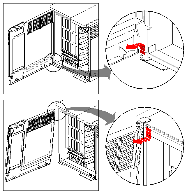
Open and remove the front door.

Note: Removal of the front door is highly recommended. The system is easier to work on and removal eliminates scratching or other damage potential. See Figure 2-1 for an example.
Unfasten the I/O panel.
Remove the old F2-equipped IO4 from the cardcage.
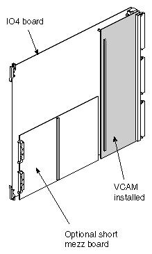
Note: If there is a short mezz board(s) on the IO4, move it/them to the new F3-equipped IO4. See Figure 2-2 for an example of the IO4 and VCAM assembly with optional mezz boards installed.
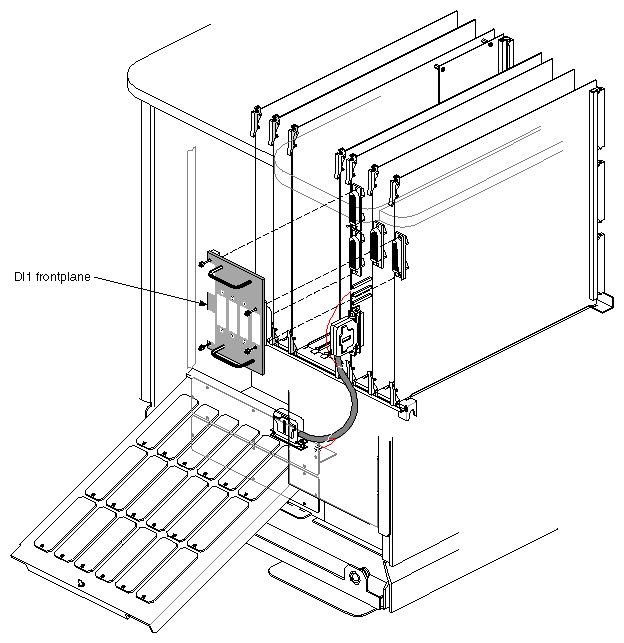
Unscrew and remove the DI1 frontplane (see Figure 2-3).
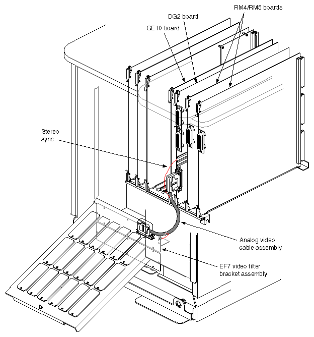
Remove the analog video cable assembly from the DG board and the video filter assembly (see Figure 2-4).
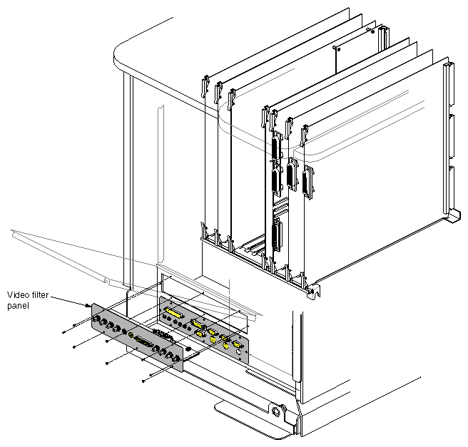
Remove the old GE10, RM4 or RM5, and DG2 graphics boards, and unscrew and remove the RE2 video filter I/O panel (see Figure 2-5).
If the system is equipped with a Sirius (VO2) board(s), refer to the Sirius Video Installation Instructions (P/N 108-0109-00x) for removal and replacement instructions.
Note: If the system has more than one VO2 or VME board installed, be sure to carefully read the information in Section 2.5.4, "Deskside InfiniteReality VME and Power Limits."
Don't install the new graphics boards until you have completed the steps in Section 2.7, "Removing and Replacing the SCSI Fan."
| Caution: Failure to replace the SCSI fan assembly can result in damage to DG4 PAB 2 paddle board components during installation or removal of the DG4 board. |
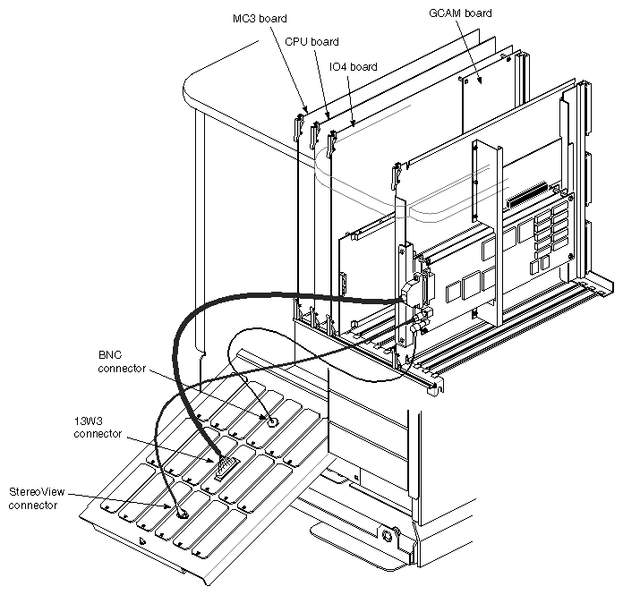
After you shut down the system and extract the IO4 and GCAM board assembly as described in Section 2.4, remove the graphics cables and board set as follows:
Disconnect the BNC, 13W3, and StereoView cables from the Extreme graphics board.
Remove the Extreme board set assembly, see Figure 2-6.
Remove the connector plates for the BNC, 13W3, and StereoView and replace them with blank connector plates.
Remove the blank I/O panel just above the standard connector set. Refer to Figure 2-5 for its location.
If the deskside Onyx system you are upgrading already has an InfiniteReality ready backplane installed, you must still install the new InfiniteReality power boards. Follow the steps in Section 2.5.3, "Installing the Power Boards on the InfiniteReality Backplane," then proceed to Section 2.6, "Replacing the Deskside OLS."
If you are unsure how to tell if the system has an InfiniteReality ready backplane, refer to Section 1.11, "Determining If the System Backplane Is InfiniteReality Ready."
| Note: The part number for a non InfiniteReality graphics backplane is 030-0310-00x The part number for the InfiniteReality ready backplane is 030-0555-00x. The 030-0555-00x board is also marked "KONA Ready." |
Prepare for removal of the old graphics backplane by disconnecting all remaining boards in the system from the backplane and pulling them out one quarter of the way. This would include the CPU, MC3, and any VME boards installed.
You should have already removed the old graphics boards and the top horizontal I/O panel from the front of the system.
In order to remove and replace the system backplane, you first remove the rear plastic panel and sheet-metal cover, as follows:
Undo the back plastic panel from the chassis by grasping the bottom of the panel and giving it a quick pull away from the chassis.
Pull the lower edge of the panel away from the chassis until it's stopped by the U-shaped metal bumper at the bottom of the chassis.
Drop the top edge of the panel down to clear the top hat.
Lift the panel away from the chassis.
Remove the sheet-metal panel from the chassis using the following procedures:
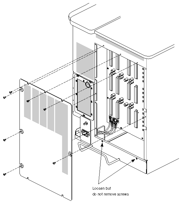
Loosen (but do not remove) the two Phillips-head screws at the bottom of the panel.
Completely remove the remaining seven Phillips-head screws holding the panel in place. Figure 2-7 shows the prepared back panel.
With the cover off, carefully remove and set aside the power boards.
After removing the outer plastic and sheet-metal covers (as detailed in the previous subsection), you can access and remove the exhaust divider, plastic baffle, and system backplane. Use the following instructions to complete the task:
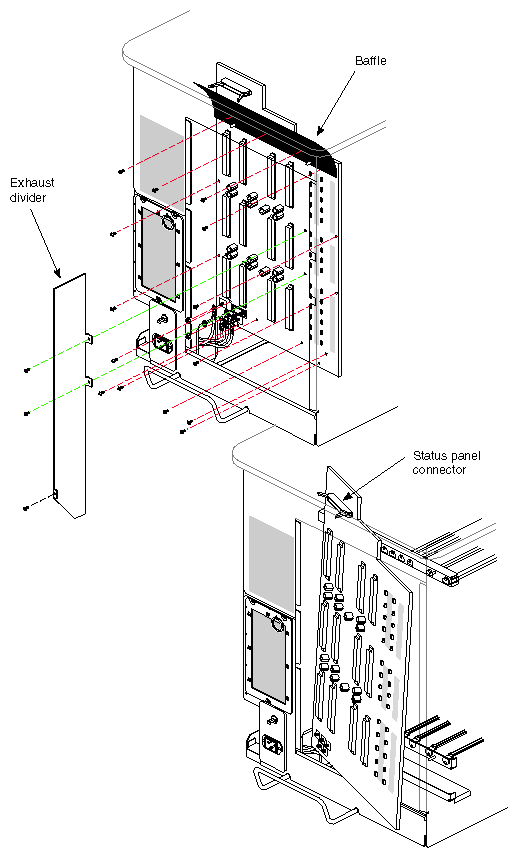
Remove the exhaust divider (P/N 040-0395-00x) by removing the three screws (see Figure 2-8). Two screws secure the middle of the divider to the backplane. The third screw can be found near the bottom of the chassis.
Lift the divider out of the chassis.
Remove the plastic baffle by prying up the bottom with your fingers (see Figure 2-8). The bottom of the baffle mounts onto two metal pins near the top of the backplane. The baffle covers the status panel connector located near the top left-hand corner of the backplane.
Disconnect the following items:
The status panel connector (top left).
48-volt connector wires (four total). Wires one and two are white and red in color, and wires three and four are solid red
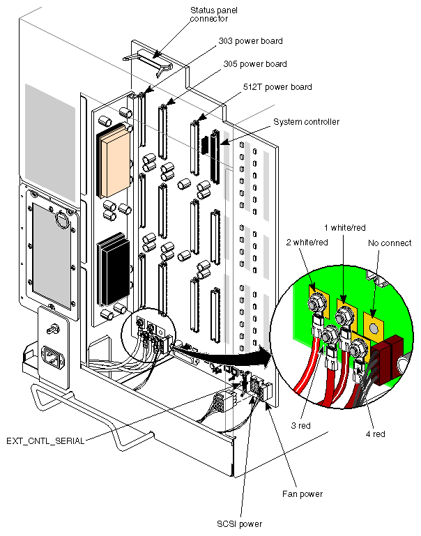
Note: These four power wires must be reinstalled in the proper order (see Figure 2-9 for the connection points). Don't push on the bolts during removal, and ensure the connectors do not touch each other when reinstalled. The 4-pin OLS controller cable.
The 2-pin SCSI power cable.
The 4-pin blower power cable.
The RS-232 system control cable.
Use a number 2 Phillips screwdriver to remove the 14 screws holding the backplane to the chassis and card guide pins.
Caution: Be careful not to damage the thermal sensor in the upper left section of the backplane area when removing or replacing the system backplane. Remove the backplane by sliding it off the four positioning tabs on the card guide shelves and angling the backplane to clear the chassis.
Install the InfiniteReality ready backplane by reversing the previous steps.
Go to the next subsection and install the three new InfiniteReality power boards (303, 305, and 512T) on the backplane. Note that the old 512 power board does not supply the same power levels as the newer 512T and should not be installed when a 512T is called for.
The InfiniteReality ready backplane uses new power boards that produce +3.45, +5, and +12 volts. The non InfiniteReality graphics backplane employs two 505 boards, one 512 board, and one System Controller board. The 505 board provides 5 volts for use by the older RE2 graphics boards. The 512 provides both 5 volts and 12 volts. The 12-volt supply gives power to the drives and VME.
The System Controller board provides 1.5 VDC for the Everest bus and also provides power for the system controller. This board can plug only in the rightmost slot because the connectors are different from the other power boards. See Figure 2-9 for an example of the power boards' installation locations.
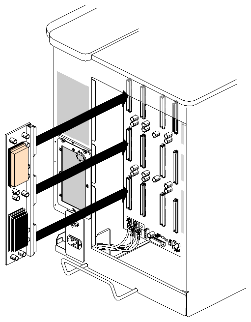
Install the power boards in the new InfiniteReality ready backplane (see Figure 2-10 for an example) by following these steps:
Install the System Controller board from the old backplane in the rightmost position on the new backplane.
Install the new 305 power board in any of the power board positions.
Install the 303 power board. Note that 303 boards take a bit more force to seat properly because of the large 3.45-V power pins.
Install the new 512T power board in the remaining power board slot.
Note: At this juncture you should stop and take a 3-V power reading on the new InfiniteReality backplane to confirm functionality. Section 1.12, "Checking 3-Volt Power on the InfiniteReality Backplane" in Chapter 1 provides information and procedural steps to accomplish this. Confirm that all electrical connections are made by visually inspecting the power boards to see if they are seated properly.
The VME power for the Onyx deskside InfiniteReality or i-Station system is variable. Depending on the line voltage and type of power boards used, the VME wattage available may be greater or less than that in RE2. All figures in Table 2-1 are based on use of the InfiniteReality 50-amp OLS.
| Note: Power output is insufficient for operation using 100-V Japanese line voltages. Only 220-V InfiniteReality or i-Station systems are supported in Japan. |
As listed in Table 2-1, there are two distinct power board configurations used in InfiniteReality deskside systems. The first configuration uses two 303s and one 512T. The second configuration uses one 303 (P/N 030-0677-00x), one 305 (P/N 030-0740-00x), and one 512T (P/N 030-0739-00x) power board. Confirm the power board configuration by removing the two rear panels. When a customer adds additional VME boards, it may be necessary to change the power board configurations. If the customer adds an RM6 the system voltage supply must be 220 VAC.
Table 2-1. Deskside Onyx InfiniteReality andi-Station VME Power
Configuration, Voltage, and Power Boards Used | Total +5V Available for VME and IO4 Mezz Boards | Total +12V Available for VME boards |
|---|---|---|
110VAC with 1 RM6 using two 303s and a 512T | 26 amps (130 watts) | 5.7 amps (68 watts) |
110VAC with 1 RM6 using a 303, a 305, and a 512T | 34 amps (170 watts) | 5.7 amps (68 watts) |
220VAC with 2 RM6s using two 303s and a 512T | 26 amps (130 watts) | 5.7 amps (68 watts) |
220VAC with 2 RM6s using a 303, a 305, and a 512T | 86 amps (430 watts) | 5.7 amps (68 watts) |
| Note: Assume an average use of 25 watts for each IO4 mezzanine board installed. |
Table 2-2 shows an example of wattage used by two different Silicon Graphics VME-based boards. Using both of these boards in the Onyx deskside system (at the same time) would exceed the allowed maximum VME wattage for most deskside InfiniteReality configurations. The exception to this rule is listed in the fourth row of Table 2-1.
Table 2-2. Deskside Onyx VME Power Use Example
System Volts and Power Board Config. | VME Board Type | Watts Used at +5 V | VME Watts Still Available |
|---|---|---|---|
110 VAC with 1 RM6 using a 303, a 305, and a 512T | VME HIPPI | 75 watts | 95 watts |
220 VAC with 2 RM6s using a 303, a 305, and a 512T | VME Sirius (VO2) | 110 watts | 320 watts |
Power used by the InfiniteReality graphics system exceeds RE2 by approximately 25%. To assure adequate system power margins, remove and replace the old 40-amp OLS using the following steps:
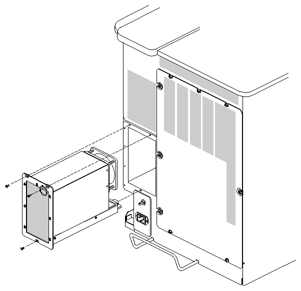
Undo the three screws holding the old OLS in place and pull it out of the system (see Figure 2-11).
Slide the new 50-amp OLS (P/N 013-1592-00x) carefully into place and confirm that it is fully connected. It should be appropriately marked or tagged as 50-amps.
Replace and tighten the retaining screws.
Install the new sheet-metal cover (P/N 013-1546-00x) and the original plastic panel that you removed to access the backplane and OLS. Do not reuse the old sheet-metal cover on an InfiniteReality system.
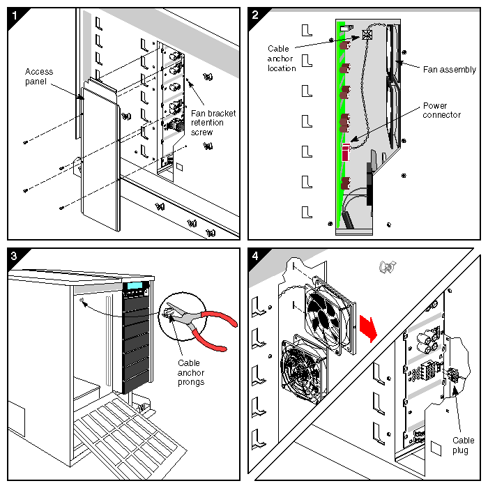
Replacement of the SCSI fan and cable assembly is required for InfiniteReality upgrades on all deskside Onyx systems. There are two metal "tongues" on the SCSI fan assembly. They protrude through the sheetmetal and into the mechanical area occupied by the DG4 board. Components on DG4 paddle boards may strike these tongues (or the plastic cable mount anchor) and cause component damage during installation or removal of a DG4. Extracting and replacing the SCSI fan is accomplished by the following steps:
Face the front of the system and remove the right-side plastic panel.
Remove the four screws holding the metal access panel and the single screw holding the fan bracket in place. Refer to Figure 2-12 for help with these steps.
Move to the front of the system, open the I/O panel, and use a pair of adjustable pliers to squeeze and push through the plastic cable mount.
Unplug the fan power cable from the SCSI backplane, then pull the fan assembly forward and out of the chassis.
Install the new fan, replace the screw, and stick the adhesive cable mount on the previous anchor point.
Plug the fan cable into the SCSI backplane, reinstall the metal access panel, and replace the plastic side panel.
After the new backplane and power boards have been properly installed, push the CPU, MC3, and any VME boards back into the system and firmly seat them in the new backplane.
The new IO4 and InfiniteReality boards should be installed next, and then the new InfiniteReality graphics I/O panel. Use the following steps to install the boards:
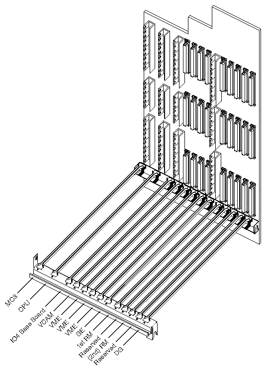
Install the new F3-equipped IO4 and VCAM (see Figure 2-13) in slot 3 to replace the old IO4 assembly. Make sure the new IO4 is properly seated into the backplane connectors and that the ejector tabs have engaged the top and bottom card guide.
Install the InfiniteReality graphics boards in the proper slots. See Figure 2-13 for the locations of all boards on the backplane connectors.
Install an air baffle in each instance where there are two unused board slots in the system cardcage. In single RM configurations, place the baffle next to the DG board.
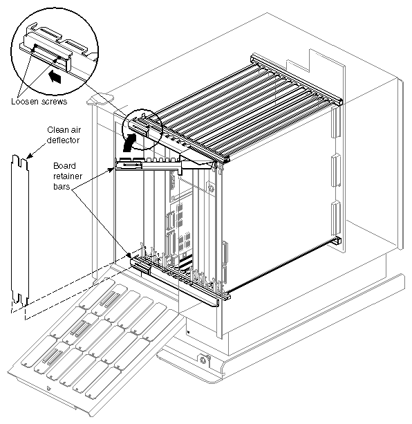
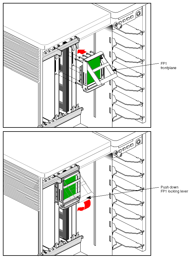
Note: Before installing the FP1 (as listed in the next step), align the pins on the front of the boards carefully with the connectors on the FP1. Install the new top board retainer assembly and frontplane (FP1) board (P/N 013-1596-00x), as shown in Figure 2-14; then install the original lower board retainer assembly.
Ensure that the FP1 locking lever is pushed all the way down (see Figure 2-15).
Install the new board placement label showing the InfiniteReality configuration.
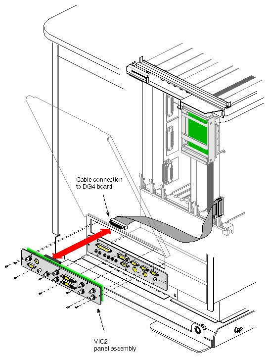
Install the new 68-pin flat video cable to the DG4.
Install the VIO2 I/O panel (see Figure 2-16) and connect the other end of the 68-pin cable to the VIO2's connector.
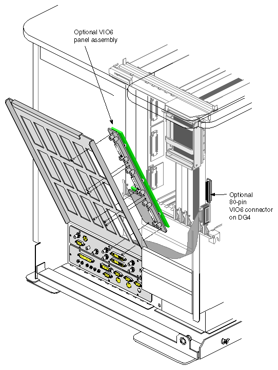
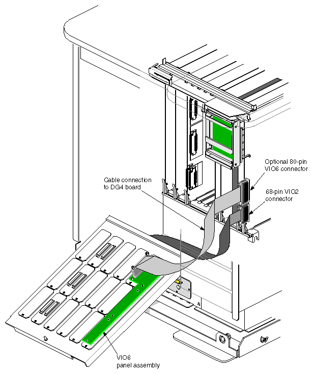
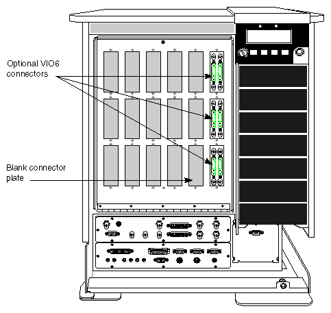
Note: If the system was ordered with the optional DG4-8, it uses an additional 80-pin I/O cable and panel (the VIO6). Use the following additional steps to install the VIO6 I/O panel and the 80-pin optional cable that connects it to the DG4-8. Remove four blank I/O panels from the rear I/O door (see Figure 2-17 for an example), and attach the optional VIO6 using eight screws.
Attach the optional 80-pin cable to the upper connector on the DG4-8 board (see Figure 2-18), and the connector on the back of the VIO6.
Close up the main I/O door taking care not to snag the 80-pin cable (see Figure 2-19).
Reinstall all screws holding the I/O door closed.
The InfiniteReality graphics upgrade does not automatically ship with a color monitor (monitors are listed as separate line items). Regardless of the monitor's origin, it must use a 13W3 connector.
See the end of Chapter 1 for 13W3 pinouts for the connectors on the VIO2, and all VIO6 13W3 connectors. The Stereoview and S-video connector pinouts are also shown.
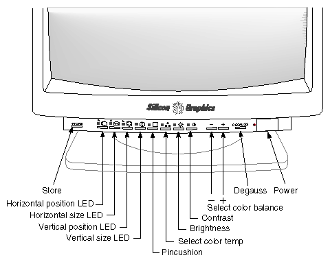
See Figure 2-20 for an illustration of a 21-inch monitor.
| Note: See the monitor's user guide for additional information on specific monitor settings and adjustments. |
Use the following steps to connect a monitor to the system.
Locate the monitor video cable. It has large 13W3 connectors on each end.
Attach one end of the monitor video cable to the 13W3 connector on the back of the monitor. Secure the screws on either side of the connector.
Attach the other end of the monitor video cable to the 13W3 connector on the deskside system's I/O panel. Secure the screws on either side of the connector.
Plug in the monitor's power connector to a properly rated power source.
For information on system power-on and diagnostics, see Appendix A.