This chapter introduces the InfiniteReality graphics upgrade hardware for Onyx IP25 and IP19-based systems. It discusses the differences between InfiniteReality and previous graphics systems used in Onyx, and provides the necessary safety and configuration information. This information is written for Silicon Graphics® system support engineers (SSEs), or other trained and authorized field personnel who are responsible for the installation, removal, or replacement of these hardware options.
Chapter 1 contains the following sections:
Section 1.3, "InfiniteReality Combiner Programming Overview"
Section 1.7, "Saving Video Format Combinations to the GE12 EEPROM"
Section 1.8, "Resizing a Single-Channel Combination Example"
Section 1.11, "Determining If the System Backplane Is InfiniteReality Ready"
Section 1.12, "Checking 3-Volt Power on the InfiniteReality Backplane"
The InfiniteReality graphics product is a next-generation graphics option that replaces RealityEngine2 as the high-end graphics board set in Onyx deskside and rackmount systems. Note that InfiniteReality upgrades are not supported in R8000® (IP21-based) systems.
If you are familiar with how the RealityEngine2 board set is installed and connected, it should be easier to upgrade an Onyx system to an InfiniteReality graphics system.
Note, however, that an InfiniteReality upgrade is far more than a "board swap" from RealityEngine2 to InfiniteReality boards. You should have some or all of the following components (depending on type of upgrade) in a basic InfiniteReality upgrade:
CD-ROM with upgrade OS and/or patch (P/N is variable).
GE12 graphics board using GE11 geometry engines (P/N 030-0681-00x).
RM6 raster manager board with 16 MB of texture RAM (P/N 030-0683-00x) or 64 MB of texture RAM (P/N 030-0684-00x). One, or two RM6 boards are supported in each deskside system and one, two, or four RM6 boards are supported in CC2 of the rack.
DG4 display generator board, two channels (P/N 030-0686-00x), or the eight-channel DG4-8 board (P/N 030-0687-00x).
FP1 frontplane board assembly (P/N 013-1596-00x).
InfiniteReality graphics VIO2 two-channel I/O board and panel with all graphics connectors (P/N 013-1342-00x), or VIO2C (P/N 013-1340-00x) for CC3 only.
The optional VIO6 six-channel output I/O board and panel (P/N 030-0765-00x).
Internal graphics I/O interface cable for two-channel, 68-pin VIO2 board (P/N 9290129), or optional six-channel, 80-pin cable for the VIO6 I/O board (P/N 9290130).
Deskside backplane (P/N 030-0555-00x), rackmount midplane (P/N 030-0556-00x), or Cardcage 3 backplane (P/N 030-0557-00x).
50-amp OLS units (P/N 013-1592-00x); one for deskside, two for CC2, and three for CC3 upgrades.
Two 1900-RPM blowers (P/N 013-1650-00x) are included with each CC3 upgrade.
Replacement master IO4 with upgraded F3 ASIC (P/N 013-1652-00x).
303 power board for rackmount CC3 and deskside upgrades (P/N 030-0677-00x).
305 power board for deskside upgrades (P/N 030-0740-00x).
512T power board for rackmount and deskside upgrades (P/N 030-0739-00x).
303x2 power board for CC2 rackmount upgrades (P/N 030-0741-00x).
305x2 power board for CC2 rackmount upgrades (P/N 030-0743-00x).
512Tx2 power board for CC2 rackmount upgrades (P/N 030-0742-00x).
Rackmount "door strip" (P/N 024-0947-00x "generic") or (024-0963-00x "R10000").
Slot assignment label for CC2 (P/N 024-0953-00x).
Slot assignment label for deskside cardcage (P/N 024-0952-00x).
Top board retainer bar for deskside systems (P/N 013-1615-00x).
Top board retainer bar for rackmount cardcages (P/N 013-1623-00x).
Deskside top hat plastic strip label (P/N 024-0945-00x).
 | Note: The 21-inch color monitor is a separate line item and is not included on the bill of material with the InfiniteReality option for Onyx systems. |
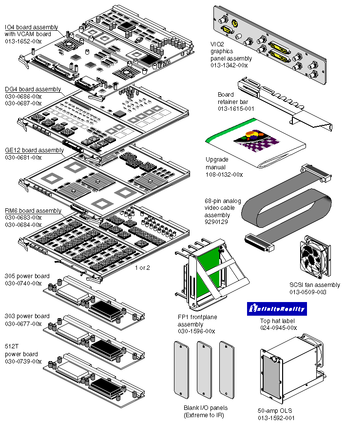
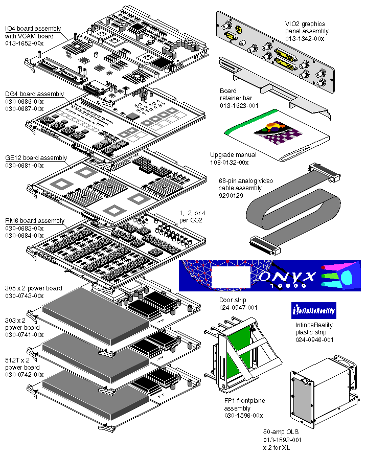
InfinteReality upgrade components for the deskside are shown in Figure 1-1. Card cage 1 and 2 InfiniteReality upgrade components for the Onyx rack are illustrated in Figure 1-2.
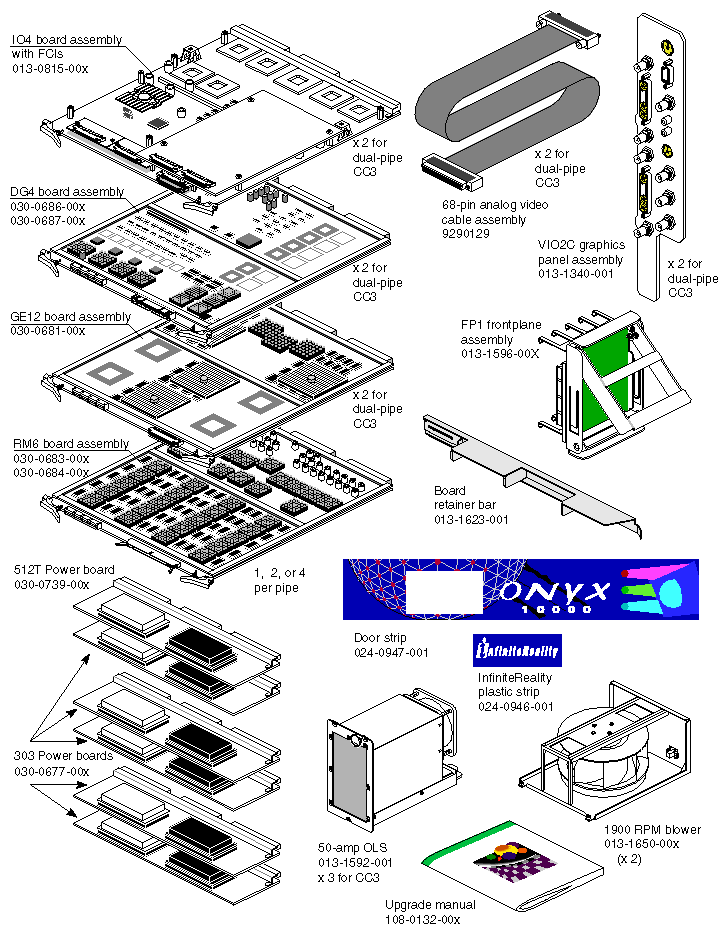
InfiniteReality upgrade components used in a CC3 upgrade are shown in Figure 1-3.
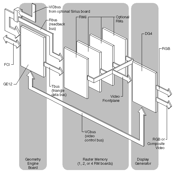
The InfiniteReality graphics board set consists of the Geometry Engine® (GE12) board, the raster memory (RM6) board(s) and the display generator (DG4) board. These boards interconnect by way of a new FP1 frontplane assembly that is not compatible with RealityEngine2 or other non InfiniteReality graphics hardware.
New power boards used with the Onyx InfiniteReality graphics boards convert the 48V available on the backplane to the 3.45 V used by InfiniteReality. Power boards (bricks) are DC-to-DC converters that take the 48 VDC from the system backplane or midplane and step it down to levels appropriate for the buses, circuit boards, and SCSI drives. Four types of power board are used with the InfiniteReality Onyx systems. You should note that the first three listed below were designed specifically to meet the needs of the Onyx InfiniteReality products.
The IO4 and memory boards used in InfiniteReality are +5 V assemblies just as they are in RealityEngine2 based Onyx.
The 303 power board generates +3.45 VDC at 120 amps for use by the GE12, DG4, and RM6 boards. There is a dual (2x) version of the 303 board (CC1 rack systems only).
The 305 power board generates 60 amps of +3.45 VDC and 60 amps of +5 VDC for use by the IO4 and memory boards. There is a dual (2x) version of the 305 board (used in Cardcage 1 in rack systems only).
The 512T power board generates +5 VDC at 50 amps and +12 VDC at 17 amps for the VMEbus. A dual (2x) version of the 512T is available for use in Cardcage 1 in the rack.
The System Controller board supplies +1.5 VDC at 30 amps for use by the EBus. This board also provides power for the microprocessor on the System Controller.
Communication between the RM6(s) and the DG4 board is over the Video Frontplane bus. See Figure 1-4 for a functional block diagram of the board set.
The GE12 board (P/N 030-0681-00x) processes OpenGL® commands and data from the Onyx system CPU board and is the first stage of the graphics pipeline.
The GE12 receives vertex data defining the location, orientation, color, and texture- mapping coordinates of a polygon. If the polygon has more than three vertices, the GE12 subdivides the polygon into triangles. Triangles are the basic polygonal working units of the system. Data output from the GE12 geometry subsystem passes over the Triangle bus to the raster memory subsystem (RM6).
Primary ASICs on the GE12 include the
host interface processor (HIP)
geometry engine distributor (GED)
geometry engines (GE11s)
back-end FIFO (BEF)
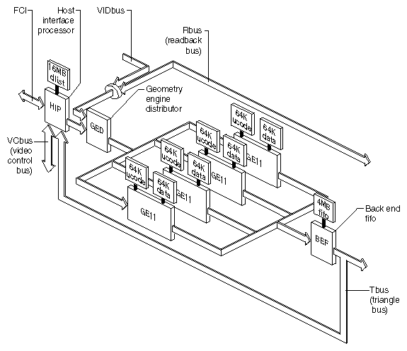
The GE12's host interface processor (HIP) ASIC interfaces with the host system through a flat cable interface (FCI) on the IO4 board. The FCI is a 64-bit wide bus that has a maximum transfer rate of 220 MB per second. Its purpose is to provide an interface on the IO4 board between the graphics subsystems and the Ibus. The FCI leaves the IO4 board and passes through the VCAM to enter the system midplane. The GE12 is installed in a dedicated slot on the backplane or midplane, which is connected directly to the FCI.
The HIP communicates with the DG4 (or optional DG4-8) board over the video control (VC) bus. The back-end FIFO (BEF) drives the triangle bus (Tbus).
The graphics processor interface and the readback bus (Rbus) feed pixel data to the geometry engine distributor (GED) ASIC. The GED distributes pixel and vertex data to the GE11 ASICs on the GE12 board.
The GE11 processors each contain three floating-point (FPU) data paths, and four internal 512 x 32 blocks of support RAM. The GE11 is also supported externally by 64K x 72-bit words of microcode, and a 64K x 32-bit wide data SRAM. The GE11's microprocessor can perform 480 million floating point operations per second (MFLOPS).
The GE11 ASICS also have these internal features:
three floating point MUL/ALU cores
address and data registers for each FPU core
float-to-fix converters for each FPU core
a 256 x 32 output FIFO for each FPU that buffers information going to the Tbus
The readback bus (Rbus) provides a path for pixels flowing from the RM6 frame buffer to the geometry engine distributor (GED).
The Video Control bus provides access to the color maps, window display modes, and cursor control modes. The bus is a direct access from the Onyx host CPU to the host interface processor (HIP) ASIC that acts as a gatekeeper on the GE12.
See Figure 1-5 for a simplified block diagram of the GE12 board.
The Raster Memory (RM6) board scan-converts triangle data from the triangle bus (Tbus) into pixel data. The triangles and other primitives are converted to 2 x 2 pixel quads that are optionally textured. The pixel quads are then sent to the frame buffer. Following the transfer to the frame buffer, the DG4 is given access to the color data stored in the completed frame. There are 16 or 64 MB of texel storage capacity (using SDRAM) on each RM6.
| Note: You cannot mix 16 MB and 64MB RM6s in the same graphics pipe. |
An RM6 functional block diagram is shown in Figure 1-6. Note that a maximum of two RM6s are supported in the deskside Onyx InfiniteReality system.
The RM6 board is composed of the following main components:
pixel generator (PG) ASIC
texel generator (TG) ASIC
eight texture manager (TM) ASICs
SDRAM-based texture memory
four texture filter (TF) ASICs
twenty image memory processors (IMPs) with four SGRAMs for each IMP ASIC
To get pixels into the frame buffer, the pixel generator (PG) must scan-convert each primitive sent over the Tbus to find the parameter values for each of the polygon's interior pixels. The PG distributes these values in 2 x 2 pixel blocks among the four TFs.
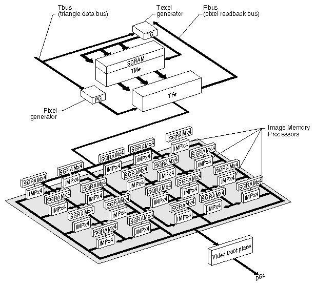
Two data paths from the Tbus facilitate processing performance. One path processes the pixels for texture mapping via the texel generator and texture managers. The other path through the pixel generator produces RGB information that is passed directly to the texture filter ASICs.
The texel generator ASIC receives both "raw" triangles and generated X and Y pixel coordinates from the pixel generator. The texel generator then scan-converts each triangle to generate texture coordinates that are passed to the texture managers (TMs). The TMs perform lookups, formatting, and initial filtering of the texel quads. The resulting texture RGB information is passed to the TF ASICS where it is combined with the basic RGB values from the pixel generator.
The TFs also perform fog calculations and texture table lookups before sending pixel quads to the IMPs. Each IMP ASIC contains four image engines, each handling a one pixel wide by two pixels high block at a time.
The IMP array receives the final color values and texture results from the texture filter.
The main responsibilities of the IMPs are to
filter the subpixel rendered image into the actual displayable frame buffer
timeshare the drawing and video display functions
decide whether to write the pixel based upon the z-buffer value
perform the alpha blending of each new pixel with the pixel value that has already been rendered at the same location
send the digital pixels to the display generator board (DG4) over the FP1 video front plane
timeshare the drawing and video display functions
Communication between the RM6(s) and the DG4 board is over the video front plane only.
The InfiniteReality board set can have up to four RM boards. Note that only one or two RM6s are supported in deskside systems. As more RM boards are added, vertical display spans are interleaved, providing higher resolution and increased pixel fill rate.
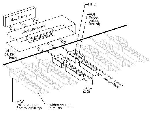
The display generator subsystem requests and receives digital frame buffer pixel data from the RM board over the video frontplane. The DG4 processes the pixel data through an XMAP ASIC that sorts the pixels and streams them onto the video packet bus.
The DG4 also handles all pixel clocking and genlocking functions. The FM2 ASIC handles the role of the functional manager.
The XMAP ASIC handles cursor display functions.
Once the processed video data leaves the XMAP, it enters the packet bus and can be sent to one of three possible outputs:
one of the video output channels
NTSC or PAL encoder (VTR channel)
The video output controller ASIC (VOC) assembly consists of
a video output formatter for generating video timing signals
a FIFO buffer
Each VOC ASIC supplies data to a 3-DAC array that feeds the analog RGB signals out.
NTSC or PAL circuitry signals come from the VOC through encoder and field buffer RAMs.
See Figure 1-7 for a functional diagram of the DG4 board.
The video output on the DG4 can support two or (optionally) eight monitor connections. The default monitor resolution supported by InfiniteReality is 1280 x 1024 at 72 Hz. DG4 total pixel output support peaks at 300 M pixels per second.
With two monitors x 1280 x 1024 x 72 Hz, only 188,743,680 (188 M) pixels per second are used. However, with eight monitors x 1280 x 1024 x 72 Hz, 754,974,720 (755 M) pixels per second is 455 M pixels above the support limit. Therefore, to use eight monitor connections, you must use a combination of lower and higher resolution monitors that is within the limit of 300 M pixels per second.
There are many options for video output with InfiniteReality graphics. The following section outlines some of the choices available using the Video Format Combiner programming utility available with all 6.2 and later OS releases.
InfiniteReality graphics provides a programming utility, the Video Format Combiner, with two interfaces:
the functional command-line interface ircombine
the graphical user interface (GUI) ircombine-gui
This section is mainly concerned with the GUI version of ircombine. For information on the command-line version of ircombine, consult the ircombine(1G) reference (man) page.
Use the Combiner only with Onyx InfiniteReality or i-Station graphics systems.
For RE2 and VTX graphics systems you must use the video out panel or other custom applications.
Both the command-line and GUI utilities create video format combinations—descriptions of raster sizes and timing to be used on video outputs—and configure the underlying framebuffer. You can use a video format combination as the current video configuration, store it as the default configuration to be used at system power-on or graphics initialization, or save it in a video format combination file. You can create a video format combination from scratch. Also, you can modify a current or default combination or a previously saved combination.
The Combiner utility is useful for applications that need multiple channels, for such uses as visual simulation, virtual reality, or entertainment. The Combiner utility instructs the video subsystem to convert digital information stored in the graphics framebuffer into a variety of video signals (or channels), ranging from standard high-resolution (1280 x 1024 and higher) to low-resolution outputs. The output can then be displayed on additional monitors or projection devices, or stored on videotape, in any combination. Output can also be genlocked to an external reference signal.
The InfiniteReality pipeline can process image, geometric, and video data concurrently at real-time rates. The pipeline can convert a full-screen, high-resolution display to a composite (NTSC or PAL) video output port: your application can record in real time whatever is being displayed on the screen.
To launch and display the Combiner's GUI, enter the following in any available IRIX window:
To specify a different display from the current workstation, such as a remote workstation, or a specific pipe of a remote rackmount system, as the target on which to display the combination, use
/usr/gfx/ircombine -targetdisplayname
| Note: The first time InfiniteReality graphics was initialized, or during the first power-on of the system with InfiniteReality graphics installed, the video output was defined for the channels available on the workstation. To reinitialize graphics, enter |
(/usr/gfx/stopgfx ; /usr/gfx/startgfx) &
at the IRIX prompt. Note that the parentheses are necessary.
In the Combiner main window, click the button for the channel you want to define or modify. See Figure 1-8 for an example of the main window interface.
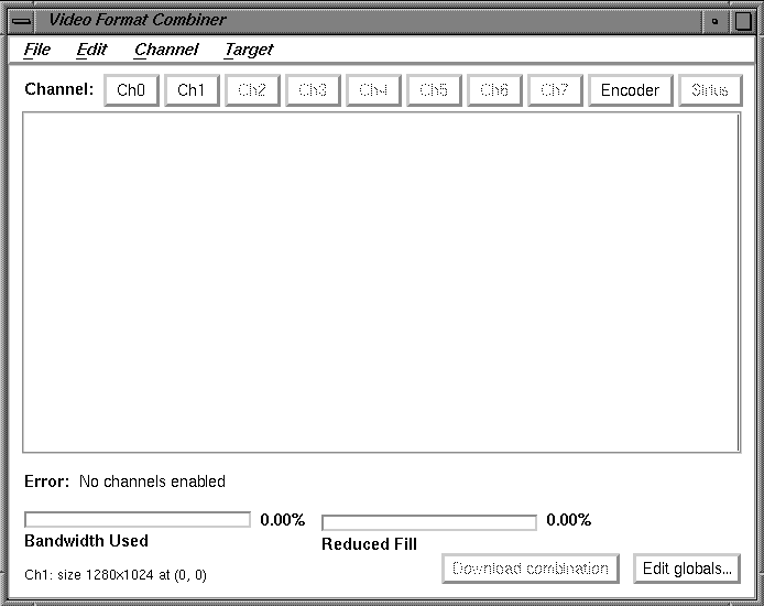
You might, for example, select Ch0 for the first channel. This selection corresponds to Chan0 connections on the InfiniteReality system's I/O panel.
The managed area is the display surface taking up most of the Combiner main window. In the following sections you can perform example exercises designed to demonstrate some of the things you can do using the Combiner. Each example starts from the Combiner's main window.
The example exercises in the following sections are based on the assumption that a Silicon Graphics multisync 21-inch monitor is connected to channel 0. If the monitor attached to channel 0 is unable to sync to any of the formats used in the example, it ceases displaying video.
If the monitor should stop displaying video during one of the examples, or during any other type of Combiner use, the following steps should provide a solution:
Connect a monitor to channel 0 that can display the required format(s). If video is still not visible, go on to step two.
Log in to the system remotely or connect an ASCII terminal to serial port tty_1, if possible. Become superuser (root) and enter the command /usr/gfx/setmon -n 72. If this does not work, enter /usr/gfx/setmon -x 72 and then restart the graphics by entering (/usr/gfx/stopgfx ; /usr/gfx/startgfx) &.
Reboot the system using the System Controller if the first two steps do not work. If, after rebooting, the video still does not display, wait for several minutes and go to the next step for an additional process.
Enter 1 on the system keyboard, then attempt to reboot the system to single-user by entering /usr/gfx/setmon -x 72 (even though you are unable to see any screen display of your inputs). Once you believe you have succeeded, reboot again.
Call your Onyx service provider for additional information and assistance if none of the previous four procedures restores your system's video output.
Before starting this exercise, be sure to read the information in the previous section, "Using the Combiner Examples."
Prior to modifying and downloading new video format combinations, you should follow the steps below. This will enable you to avoid rebooting the graphics system if you select a combination of window sizes that do not encompass the combiner main window controls or an IRIX shell window.
Bring up an IRIX shell window and reduce it to 80 x 24 using the size option on the pulldown menu from mouse button three.
Drag the IRIX shell to the lower left corner of the screen.
Launch the Combiner main window (if you have not already done so).
Position the Combiner's main window in the upper left corner of the screen.
Resize the Combiner's main window so that none of the IRIX shell window is covered. Do this by clicking the lower right corner of the Combiner main window and moving it upward.
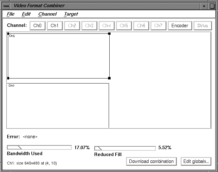
After completing these preliminary steps, go on to select the first channel. Figure 1-9 shows the main window with channels 0 and 1 in the managed area.
 |
Select the first channel to modify (channel 0) by following these steps:
Click the Ch0 button on the Combiner main window.
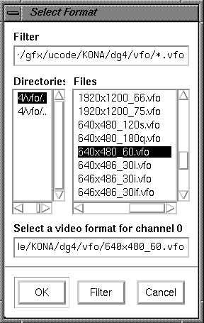
Note: When you click a channel pushbutton, the Files window appears. You can then select a video format for that channel (see Figure 1-10 for an example). Click the up or down arrows in the Files window to find the 640x480_60.vfo file, then select it.
Click OK. The Ch0 rectangle appears in the Combiner's main window.
Click on the bottom line (not the corner) of the rectangle and drag it to the bottom left corner of the main window.
Go on to the next section and select the format for channel 1.
Select and modify channel 1 using the following steps:
Click the Ch1 button on the main window.
Move the cursor to the Files window and click the 640x480_60.vfo file option. (This step assumes that the Files window was left open at the end of the last section.)
Click the OK button. A channel 1 (Ch1) rectangle appears in the upper left portion of the Combiner main window.
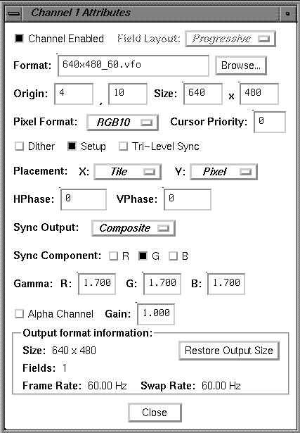
Note: Just for this example, you will precisely set the origin of channel 1 to (4,10). This could be accomplished by clicking on the line of the rectangle and dragging it, as you did channel 0. However, the Ch1 origin will be numerically specified by editing the Ch1 attributes in the following steps. Bring up the Attributes window by double-clicking the Ch1 button in the Combiner main window. The Channel 1 Attributes window appears.
Click the cursor in the first (far left) "Origin" box.
Replace the value in the left Origin box (the x-origin box) with a 4 and then press <Enter>.
Move to the right Origin box (the y-origin box) and replace the value with a 10, then press <Enter>. See Figure 1-11 for an example.
Click the Close button on the Attributes window.
Move the cursor to the Combiner main window and click the Download combination button.
At this point, the video system is displaying the configuration specified in the exercise just completed:
Channel 0 is displaying the lower left portion of the frame buffer where you originally placed the IRIX shell window.
Channel 1 is displaying the upper left portion of the frame buffer where the InfiniteReality Combiner's main window was placed.
To return to the 1280 x 1024 video output, enter /usr/gfx/setmon -n1280x1024_72 in the IRIX shell window.
Go on to the next example or close the Combiner's main window.
Before starting this exercise, be sure to read the information in the section "Using the Combiner Examples".
This example assumes that the Combiner main window is open. If it is not, go to the section "InfiniteReality Combiner Programming Overview", and launch the Combiner using the information in that section.
In the Combiner main window, select "New" from the File pulldown menu. Then click the OK button in the warning box. You are now ready to create and save a new video format combination to the GE12's EEPROM. The video format consists of two channels; each one is a 960x680_60.vfo format. Use the following steps to make and save all the changes:
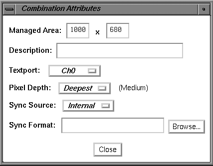
Click the Edit globals button in the main window's bottom right corner. The Combination Attributes window appears.
Change the Managed Area fields at the top of the Attributes window to read 1000 in the left hand box and 680 in the right hand box. See Figure 1-12 for an example of the Attributes window.
Click the Attributes window's Close button.
Click the Ch1 button in the Combiner's main window. The Select Format box appears.
Find and double-click the 960x680_60.vfo file format.
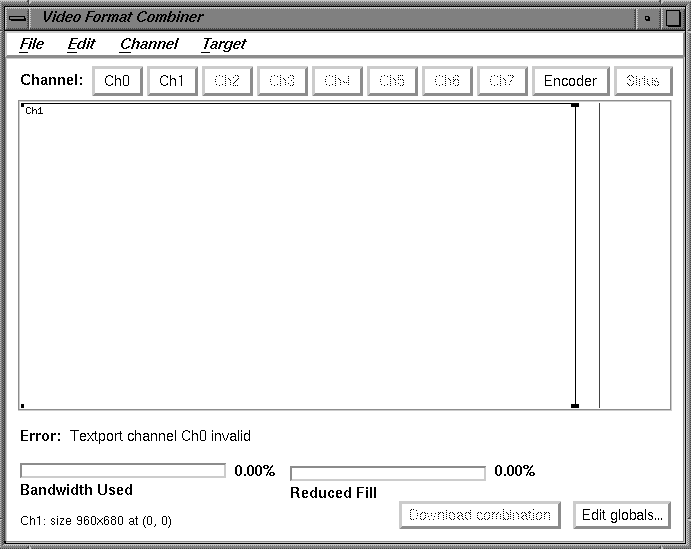
Note: At this point, an error message appears at the lower left corner of the Combiner's main window. It says "Textport channel Ch0 invalid." (In this example, the error condition goes away after you define Ch0.) While this or any other error message appears in the main window, you cannot use the "Download combination" or "Save to EEPROM" functions. See Figure 1-13 for an example error message. Click and drag the channel 1 (Ch1) box on the main window to the right until it is blocked by the red vertical line.
Note: The red line represents the right-hand boundary of the specified Managed Area (1000) that you entered in step 2. The excess space to the right of the red line represents unusable area. The combiner does not permit you to position channels in that area.
Click the Ch0 button in the Combiner main window. The Select Formats box appears.
Find and double-click the 960x680_60.vfo file format.
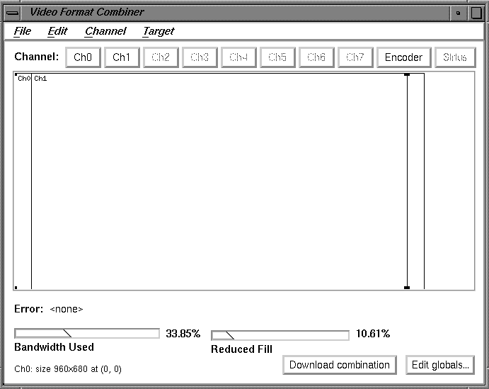
Note: At this point we have specified a video format combination with two video formats that are both equal to 960x680_60. The two channels are slightly offset, but mostly overlapping. See Figure 1-14 for an example of how the overlapping channels appear.
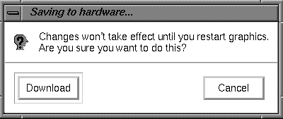
Go to the File pulldown menu in the Combiner's main window and select "Save to EEPROM." The "Saving to hardware" dialog box appears.
Click the Download button (see Figure 1-15).
| Note: The format combination is now loaded in the GE12's EEPROM, but it does not take effect until the graphics subsystem is restarted. |
Go to the File pulldown menu on the main window and select "Exit."
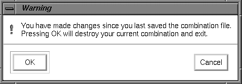
Click the OK button when the Warning dialog box appears (see Figure 1-16).
Enter the following in the IRIX shell window to restart system graphics: (/usr/gfx/stopgfx ; /usr/gfx/startgfx) &.
When the Login window appears, log in as root (superuser). The video system is now outputting a 960x680_60 format on channels 0 and 1.
Note: The video system retains this configuration even after rebooting because the 960x680_60 Video Format Combination is saved in the GE12's EEPROM.
To reset the EEPROM to the standard 1280 x 1024 format combination, enter /usr/gfx/setmon -n 1280x1024_72 at the IRIX prompt. Then restart the graphics system (as in step 13) to activate the format combination reset. When the Login window appears, log in as root.
Go on to the next example section for an additional Combiner exercise.
Before starting this exercise, be sure to read the information in the section "Using the Combiner Examples".
This example assumes that the Combiner main window is open. If it is not, go to the section "InfiniteReality Combiner Programming Overview", and launch the Combiner using the information in that section.
In this final example you create a single-channel combination that is "static resized" and saved to and loaded from a combination file. Follow these steps:
Open an IRIX shell window, click the third mouse button, and use the Size pulldown menu to change the shell to 80 x 24.
Place the 80 x 24 shell window behind the Video Format Combiner main window, but make sure the command-line prompt is visible.
Click the Ch0 button on the Combiner's main window. The Select Format window appears.
Find and double-click the 1280x1024_72.vfo file. The channel 0 (Ch0) rectangle fills the entire 1280 x 1024 managed area in the main window.
In the Channel pulldown menu, select Grab Window. The cursor turns into a cross.
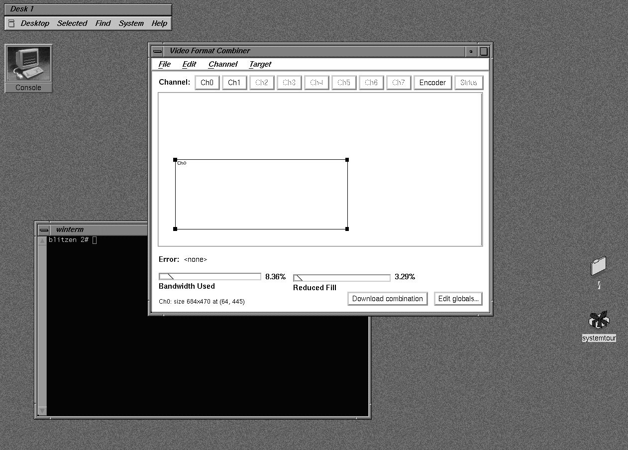
Move the cross (cursor) into the IRIX shell window and click the mouse button. The rectangle in the Combiner's main window representing Ch0 now represents the area of the frame buffer covered by the 80 x 24 IRIX shell that you clicked in. See Figure 1-17 for a screen example.
Note: This area becomes resized to fit the entire channel 0 output when the combination is loaded. A channel's input area can also be resized by clicking and dragging any of the four corners of its main window rectangle. That resizing method is not covered in this exercise.
 | Caution: Do not move the IRIX shell window until you complete this exercise. |
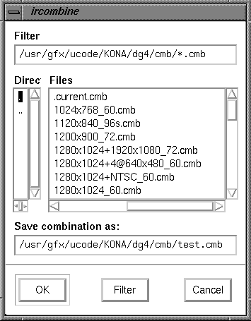
From the File pulldown menu on the Combiner main window, select Save As. The ircombine window appears (see Figure 1-18).
In the "Save combination as" field, enter test.cmb at the end of the path, then click the OK button.
Select "Exit" from the File pulldown menu on the Combiner's main window.
Type /usr/gfx/setmon -ntest at the IRIX prompt and press <Enter> in the shell window you clicked in step 6. The screen blanks momentarily, then displays the IRIX shell window resized to 1280 x 1024 (the entire screen display).
Note: If no usable window appears, use the following information to recover to the default video display combination: Log in to the system remotely or connect an ASCII terminal to serial port tty_1 if available. Become superuser (root) and enter the command /usr/gfx/setmon -n 72. If this does not work, enter /usr/gfx/setmon -x 72 and then restart the graphics by entering (/usr/gfx/stopgfx ; /usr/gfx/startgfx) &. Note that the brackets and ampersand are necessary.
Reboot the system using the System Controller if the previous methods do not work.
Revert to the previous display configuration by entering /usr/gfx/setmon -n 1280x1024_72. The entire screen should reappear in the standard 1280 x 1024 format.
Select "Exit" from the File pulldown menu on the Combiner's main window to conclude the exercise.
The Combiner interface has many functions besides those listed in the previous examples. You can use the Combiner to
define a channel using an on-screen window as input
copy an existing channel format and content to a new channel
align one channel with another
change the video format for a channel (or delete it entirely)
edit the attributes (size, pixel format, and so on) of a channel
select the "field layout" order in which data is scanned from the framebuffer
select and copy a video format stored in a different file
choose an output pixel format for a particular channel
control cursor behavior in overlapping rectangles by setting the cursor priority
allocate pixel width and depth for framebuffer fields
set horizontal and vertical phase for a given channel
specify whether sync components have sync enabled by default
modify the brightness characteristics of the monitor
change the default output video gain value for a channel
save a combination of all the channels present in the Combiner's main window and make global changes to them
arrange the pixels (set pixel depth) in the framebuffer to optimize framebuffer output speeds
select the InfiniteReality internal sync (or use an external source that is connected to the "Genlock In" port)
save a video format combination as a default and write it to EEPROM
run a user-defined hardware configuration simulating more RM6 boards than you have installed (used when an application is too large)
The information in this section is intended only as an introductory overview of the Combiner. For more detailed information on using the Combiner with your Onyx InfiniteReality graphics system, see the InfiniteReality Video Format Combiner User's Guide (P/N 007-3279-00x).
There are limitations on the number of RM6 boards the deskside InfiniteReality system supports. There are also limitations on the amount of VME power available (see Section 2.5.4, "Deskside InfiniteReality VME and Power Limits" in Chapter 2 for more information).
Table 1-1 provides some basic site preparation information for the deskside system.
Table 1-1. Deskside System Site Preparation Configurations
System | Watts | Amps | BTU/hr |
|---|---|---|---|
110 V desk IR (1 RM6) | 2050 | 18.75 | 6500 |
220 V desk IR (2 RM6s) | 3000 | 13.75 | 8100 |
| Note: The wattages shown in Table 1-1 indicate power drawn from the wall, unlike previous site preparation information that showed internal power-supply output. Japanese 100 V power is inadequate to support InfiniteReality deskside systems. In Japan, only 220 V InfiniteReality deskside systems are allowed. |
Chassis dimensions, weights, floor loadings, and airflow clearances remain identical to those listed for all Onyx systems in the previous version of the CHALLENGE/Onyx Site Preparation Guide.
Table 1-2 shows the basic site preparation information for a single-pipe (two OLS) InfiniteReality rackmount system. The wattages shown indicate single-phase power drawn from the wall rather than internal power-supply output.
Table 1-2. Rackmount Site Preparation Information
System | Watts | Amps | BTU/hr |
|---|---|---|---|
220 V rack IR (1-4 RMs) | 6000 | 30 | 20,000 |
220 or 400 V rack IR with 3 Gfx pipes | 9000 | 45 | 30,000 |
There are three specific ways to identify if the system you are upgrading has an "InfiniteReality ready" backplane already installed:
Yellow silkscreen is used on the InfiniteReality backplane. The term "KONA Ready" is also silkscreened on the lower left corner of the power board side of the backplane.
There are 3.45-V power pins adjacent to the graphics connectors (these are not installed on non InfiniteReality backplanes).
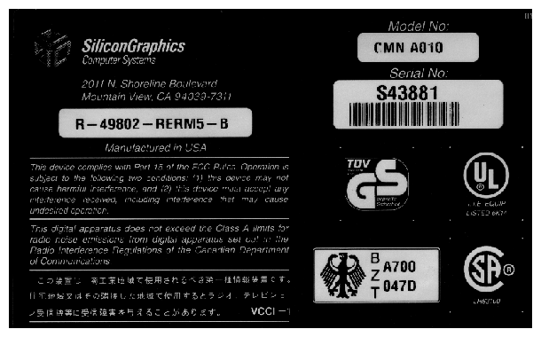
Systems shipped with InfiniteReality ready backplanes use a -B marketing code on the system certification label. The label (see Figure 1-19) is located on the upper left on the back of the deskside Onyx system and on the right side of the back of the rack (near the base).
Note: It is possible that a system originally shipped with an InfiniteReality ready backplane (and a -B marketing code) could have been modified. If the backplane was replaced after arriving at the customer site, it may have had its backplane replaced with an older non InfiniteReality backplane. Visually inspect the backplane to confirm if it is InfiniteReality ready.
After you install the InfiniteReality backplane, it is highly recommended that you check the 3.45-V power pins before installation of the new graphics board set.
| Note: The system controller does not monitor or provide information on the 3.45-V levels in the InfiniteReality backplane. Confirming the 3.45-V level must be done manually. |
To verify 3.45-V levels on the backplane, use the following steps:
Install the new 303, 512T, and 305 power bricks as applicable.
Turn on system power.
Obtain a voltmeter and set it to measure low-level DC voltage.
Attach the ground "black" probe to chassis ground.
Use the hot "red" probe to touch one of the "gold" 3.45-V power pins located between the DG or RM board connectors on the board connection slot.
Verify that the reading is +3.45 volts +/- 5%.
Shut down system power and proceed with the upgrade.
Keep the following in mind when upgrading an Onyx system to InfiniteReality graphics:
The Onyx system must have the InfiniteReality ready backplane or midplane (marked KONA Ready) installed.
Always replace the existing OLS(s) with an InfiniteReality 50-amp OLS(s).
Note: At time of publication, various warning and informational stick-on-labels were planned for the 50-amp OLS units. Apply these labels where applicable. You cannot use RealityEngine2 RM4 or 5, DG2, GE10, or GE10V boards in an InfiniteReality system.
The master IO4 and VCAM assembly in the InfiniteReality system must be F3 based (P/N013-1652-00x) or later (see Figure 1-20).
Note: Lift the heat sink off the F3 ASIC to confirm that it is labeled F3 "Rev B" or later. Also note that the VCAM used on the assembly has the IC removed at location E6D3. The VCAM part number should be (030-0500-206) Rev A or later. Mixing different types of pipes (such as an InfiniteReality in CC2 and RealityEngine2 in CC3) is not supported.
You cannot use a DI1 frontplane assembly board from a RealityEngine2 graphics board set on the InfiniteReality graphics boards.
You may not mix RM6-16 (P/N 030-0683-00x) and RM6-64 (P/N 030-0684-00x) boards in the same InfiniteReality graphics pipe.
Note: There is no deskside "top hat" replacement part shipped with the deskside InfiniteReality upgrade kit. Only the top hat plastic strip label (P/N 024-0945-00x) is installed on deskside upgrades.
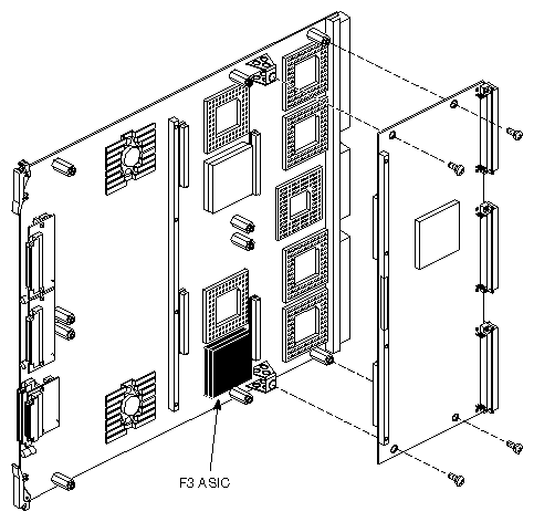
Figure 1-21 shows the pinouts of the S-Video connector on the Onyx InfiniteReality system.
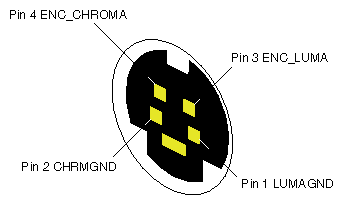
Figure 1-22 shows the pinouts for the StereoView connector on the Onyx InfiniteReality system.
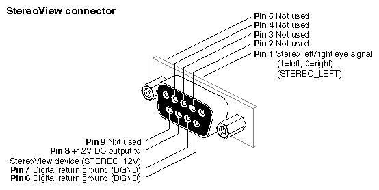
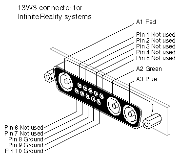
Figure 1-23 shows the pinouts for the 13W3 monitor connectors on the Onyx InfiniteReality system.