This chapter describes how to upgrade an existing CHALLENGE, POWER CHALLENGE, Onyx, or POWER Onyx with an IP21 CPU board.
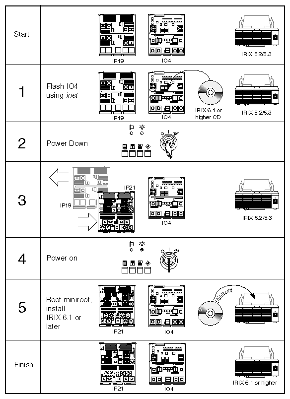
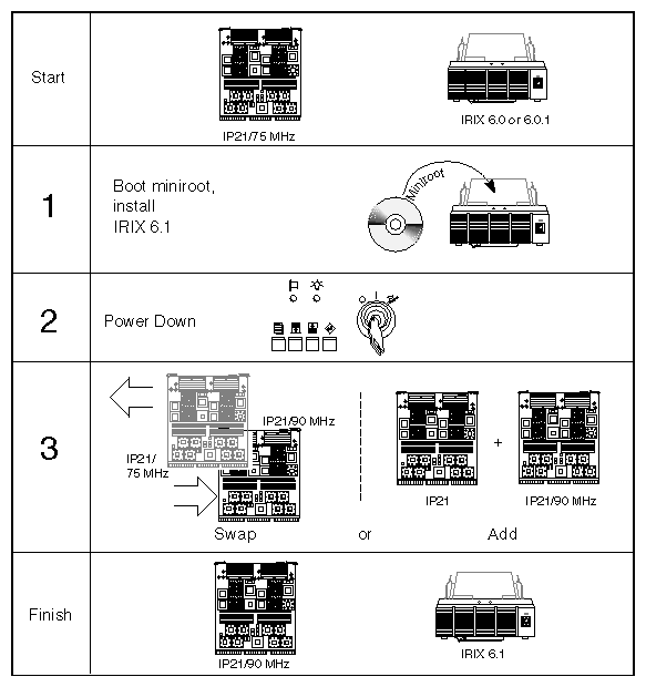
Figure 2-1 provides an overview of the IP19-to-IP21 upgrade. Figure 2-2 provides an overview for upgrading an IP21/75 MHz and IRIX 6.0 or 6.0.1 configuration to an IP21/90 MHz system with IRIX 6.1.
 | Caution: To upgrade a CHALLENGE or Onyx system to a POWER CHALLENGE or POWER Onyx model, the existing system must be running IRIX 5.2 or 5.3. |
 | Note: If you are upgrading from an IP21/75 MHz to an IP21/90 MHz board, or from IRIX 6.0 or 6.0.1 to IRIX 6.1, you do not need to reflash the IO4 PROM. |
The steps to upgrade the system are given below. It is crucial that you perform these steps in the correct order to help ensure a successful installation.
Ensure that the system is stable and does not have any known problems. In addition, ensure that the system already has the required retrofit modifications. See the CHALLENGE and Onyx Retrofit II Requirements (p/n 802-0113-001).
Note: To upgrade a CHALLENGE or Onyx system to a POWER CHALLENGE or POWER Onyx model, the existing system must be running IRIX 5.2 or 5.3. Verify that the customer's system has been backed up in a way that the customer understands and can verify.
Verify that you have all of the required components before proceeding with the installation. See Section 2.2, "Checking the Kit Contents."
Verify the minimum board and operating system revision levels. See Section 2.3, "Verifying Operating System and Board Revision Levels."
Flash the PROM on the master IO4 board with the IO4 PROM software from the IRIX 6.1 or later distribution media. See Section 2.4, "Flashing the IO4 PROM."
Power off the system and replace the old IP19 board with the IP21 board(s). See Section 2.5, "Installing the IP21 Board." (You cannot use both IP19 and IP21 boards in the same system.)
Power on the system and verify the new configuration by using the hinv command and stand-alone diagnostics. See Section 2.7, "Testing the IP21 Board Installation."
Boot the IRIX 6.1 or later miniroot from CD-ROM and install IRIX 6.1 or later and associated patch software. See Section 2.8, "Software Installation."
Caution: Also ensure that the proper application software for 6.1 or later is installed. Pack and return the old IP19 board(s) with its SRAM SIMMs in place. See Chapter 3, "Returning the Old CPU Board."
The following describes how to upgrade or add the IP21/90 MHz board or boards to a system with existing IP21/75 MHz board(s). There are two types of upgrades:
upgrading or adding just the IP21/90 MHz board(s)
upgrading with both the IP21/90 MHz board(s) and IRIX 6.1 software
If you are upgrading from an IP21/75 MHz board(s) to the IP21/90 MHz board(s), and the system already has or doesn't require IRIX 6.1, the general procedure is to swap out or add the applicable boards.
| Note: The IP21/75 MHz board and the IP21/90 MHz board are compatible and may coexist in the same system. |
It is crucial that you perform these steps in the correct order to help ensure a successful installation.
Here are the specific steps to follow:
Ensure that the system is stable and does not have any known problems.
Verify that the customer's system has been backed up.
Verify that you have all of the required components before proceeding with the installation.
Power off the system and replace the old IP21/75 MHz board with the IP21/90 MHz board(s), as applicable. See Section 2.5, "Installing the IP21 Board."
Power on the system and verify the new configuration by using the hinv command. See Section 2.7, "Testing the IP21 Board Installation."
Pack and return the old IP21 board(s), with its SRAM SIMMs in place, if applicable. See Chapter 3, "Returning the Old CPU Board."
If you are upgrading from an IP21/75 MHz to an IP21/90 MHz board, and you are also switching from IRIX 6.0 or 6.0.1 to 6.1, it is recommended that you install IRIX 6.1 before you install the IP21/90 MHz board(s). If a problem occurs after software and hardware installation, the trouble is most likely due to a bad IP21/90 MHz board and not because of an improper software installation.
The steps to upgrade the system are given below. It is crucial that you perform these steps in the correct order to help ensure a successful installation.
Ensure that the system is stable and does not have any known problems.
Verify that the customer's system has been backed up.
Verify that you have all of the required components before proceeding with the installation.
Boot the IRIX 6.1 miniroot from CD-ROM and install IRIX 6.1 and associated patch software. See Section 2.8, "Software Installation."
Power off the system and add or swap out the IP21 board(s). See Section 2.5, "Installing the IP21 Board." (The IP21/75 MHz and IP21/90 MHz boards are compatible.)
Power on the system and verify the new configuration by using the hinv command. See Section 2.7, "Testing the IP21 Board Installation."
Pack and return the old IP21 board(s), if applicable. See Chapter 3, "Returning the Old CPU Board."
Be sure to follow the safety guidelines outlined in this section, before proceeding with the installation procedures.
 | Warning: Installation of these upgrades requires specific training and technical knowledge. These instructions are provided for Silicon Graphics system support engineers or other Silicon Graphics trained personnel only. This equipment utilizes electrical power internally that is hazardous if the equipment is improperly disassembled. |
Follow these ESD preventive measures:
Use a ground strap when installing and removing peripherals.
Be sure that you and all of the electrical equipment that you handle during this installation remain at a common ground potential.
Remove a board from its antistatic bag only when you are properly grounded with a ground strap, and only when you are working on the board or installing it.
Do not use an ohmmeter on a board.
The following subsections discuss upgrade issues that affect sites.
The power consumption of the IP21 board is almost identical to that of the IP19. There are no changes in the system power requirements (such as the number of OLSs and power boards) and no changes in the site power or cooling requirements as a result of the IP21 upgrade.
It is recommended that IRIX 6.1 or later be used with the IP21 upgrade. Be aware that IRIX 6.1 does not work on an IP19-based system. If you back out an upgrade and reinstall the IP19 board, you must also reinstall IRIX 5.2. See Section 2.9, "If Problems Occur."
POWER CHALLENGE (server) systems and upgrades may ship with IP21 boards
(such as p/n 030-0625-107) that cannot be used in POWER Onyx (graphics) MP systems or in POWER CHALLENGE MP systems with the Data Visualization Console.
| Note: There are different versions of the IP21 board (see Table 2-1 and Table 2-1 for more information). |
Be sure to double-check the identity of these server-only boards by examining both BBCC chips. The locations of the BBCC chips on the IP21 board are shown in Figure 1-1. Each chip is marked with a part number, which is just visible beside the heat sink. (The first digits may be covered). Figure 2-3 shows the part number location on one of the BBCC chips.
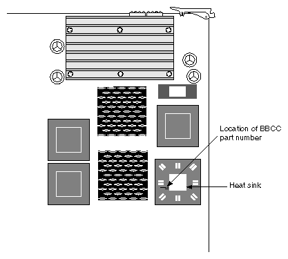
| Note: Figure 2-3 shows only one of the two BBCC chips, but you should examine both BBCC chips to verify their part numbers. |
Table 2-1 and Table 2-1 list the part numbers and their uses.
Table 2-1. IP21/75 and BBCC Versions Use in Server and Graphics Systems
IP21/75 MHz Board Part Number | BBCC Part Number | Graphics Use | Server Use |
|---|---|---|---|
030-0625-107 and 030-0625-109
(dual-processor version for
CHALLENGE only) | 099-0062-003 (Revision C) | No | Yes |
030-0625-108, 030-0625-110 through 030-0625-112 (or higher, dual-processor version) | 099-0062-004 (Revision D) | Yes | Yes |
030-0636-007 or higher (single-processor board for CHALLENGE, Onyx, or Extreme systems) | 099-0062-003 (Revision C) | Yes | Yes |
Table 2-2. IP21/90 and BBCC Part Number Use in Server and Graphics Systems
IP21/90 MHz Board Part Number | BBCC Part Number | Graphics Use | Server Use |
|---|---|---|---|
030-0702-002 (dual-processor version) | 099-0062-003 (Revision C) | No | Yes |
030-0858-001 (dual processor) and 030-0703-002 (single processor) | 099-0062-004 (Revision D) | Yes | Yes |
All IP21-based systems shipped from the factory adhere to this restriction. All dual-processor spares that use the later (-004 and later) revision of the BBCC chip can be used in either server or graphics systems.
As a precaution, do not move server-only IP21 boards from server systems to graphics systems without verifying the board and BBCC part number in Table 2-1 and Table 2-1.
| Note: You can also check the BBCC chip revision level through software. See Appendix B for more information. The operating system restricts operation to single-processor level if incorrect BBCC revisions are present (see Section 2.8.6). |
POWER CHALLENGE systems with more than seven IP21 boards (14 total CPUs) may be affected with a flow control congestion deadlock in an earlier revision of the EPC chip (on the IO4). This results in degradation of Ethernet performance, because the integral Ethernet port ceases to receive data packets.
There are two solutions to this problem. One is to use the new IO4 with Rev C of the EPC; "PCA IO4B," 030-0646-104. All new systems can be expected to ship with this revision.
The other solution is to use an EFAST VMEbus Ethernet controller board instead of the Ethernet controller on the IO4 board. Systems shipped before the EPC Rev C was available, shipped with the EFAST board (see Section 2.6).
| Note: The IRIX 6.0 or later operating system running on R8000 processors permits larger memory configurations (beyond 2 GB, up to 16 GB) than earlier 5.2 operating systems. If a system develops memory problems after you have installed an IP21 upgrade or upgraded the memory beyond 2 GB, submit a logged hardware error report with a SIMM inventory to Customer Service for evaluation. Customer service will determine if a newer version of the MC3 board (030-0614-005 or later) would improve the situation. (In some cases, the SIMMs may be the problem.) |
POWER Onyx systems with more than four IP21 CPU boards are subject to the same restrictions as outlined in Section 2.1.4.4, "Large POWER CHALLENGE Systems," above.
The GE10 board is not flashed at any time during the upgrade. Only the IO4 board is flashed. If you back out an upgrade and reinstall an IP19 board, no additional steps are required to make the GE10 work with the IP19 board. See Section 2.9, "If Problems Occur," for information on backing out an upgrade.
This section lists the major contents of the IP21 upgrade kit:
IP21 board
Note: There are a number of different revision levels of this board. See Table 2-1 and Table 2-1 for additional information regarding differences among the boards. IRIX 6.1 or later CD-ROM
Shipping box in which to pack the old IP19 or IP21 boards
RMA labels for old IP19s
SC4-S4D-6.1 or later (software for server systems)
SC4-W4D-6.1 or later (software for graphics systems)
| Note: Section 2.1.4, "Important Site Guidelines," contains information about IO4 board revisions in large CHALLENGE installations. |
| Caution: To upgrade a CHALLENGE or Onyx system to a POWER CHALLENGE or POWER Onyx model, the existing system must be running IRIX 5.2 or 5.3. |
The system you are upgrading must be at the Retrofit II level or later. Even though all existing systems should have already been retrofitted with the proper hardware and firmware, you should verify that the system you are upgrading meets the minimum requirements. See the CHALLENGE and Onyx Retrofit II Requirements (p/n 802-0113-001).
The next part of the IP19-to-IP21 upgrade process is flashing the IO4 PROM using code contained on the IRIX 6.1 or later CD. This new PROM code is necessary for the IO4 board to work with the IP21 board.
| Note: If you are upgrading from an IP21/75 MHz to an IP21/90 MHz board, or from IRIX 6.0 or 6.0.1 to IRIX 6.1, you do not need to reflash the IO4 PROM. However, if you are upgrading an IP19 system that is running a beta version of IRIX 6.0, contact the regional beta site coordinator for special instructions on how to flash the IO4 PROM. |
There are two ways to flash the IO4 PROM:
under the IRIX operating system using inst -f
through the command monitor (IO4 prompt) using flash -T
Either method produces the same result. However, the inst -f method is recommended, since it allows the system to have limited operability in case of a problem (see Section 2.4.1 for additional information). Just make sure that you do not reboot or issue the halt command if a failure should occur.
This is the recommended IO4 flashing method. Follow the steps given below in this section to flash the IO4 PROM with IRIX running.
| Caution: If the installation fails, do not reboot or halt the system. Instead, retry the installation. If installation continues to fail, continue running the system until a replacement IO4 board can be obtained. It is very important to have the system running, so that the operating system tools and commands can be available to diagnose failures. |
Using an ASCII terminal, boot the system and log in as root.
Note: It is possible to run this procedure using a graphics monitor; however, it is generally safer to run the steps through an ASCII terminal in case the graphics subsystem fails during installation. (Optional) On a laptop computer, turn on the record option, or open up a script file so that you can record and later review problems that may occur during the upgrade.
Create a copy of the current IO4 flash code by typing the following command:
# cp /usr/cpu/firmware/IO4prom.bin /usr/cpu/firmware/io4prom.bin.save
Note: If the installation fails, you can use the original code to reflash the IO4 board. If a CD-ROM drive is not already installed on the system, install it now. If the system does not have a single-ended SCSI bus with an available ID for the drive, turn to Appendix A, "Installing an External CD-ROM Drive," for instructions.
If required, mount the CD-ROM drive as shown in the following example:
mount -r /dev/dsk/dks0dns7/CDROM
where n is the address of the CD-ROM reader.
Install the IO4 PROM software from the 6.1 or later distribution media using inst:
inst -f /CDROM/dist/io4prom
This copies a new PROM image from the distribution CD and reflashes the contents of the flash PROM in the IO4. This new flash code is required to boot the IP21 board and is backwards-compatible with the IP19 board. If multiple IO4 boards are present, all of these boards are flashed with the new PROM contents as well.
Note: The newly flashed IO4 board can operate with either the IP19 or IP21. No further steps are required to reflash any of the boards, including the IO4, GE10, or the old IP19. In addition, IRIX 6.1 or later does not officially support the IP19 board. You should normally install IRIX 5.2 or 5.3 to operate with the IP19 board. You should then see a display similar to the following:
Default location of new software is xxxxxx

If you are a first-time inst user, give the command "help beginner".

Inst Main Menu
 1. from [source]                 Specify location of software to be installed
 2. list [keywords] [names]       Display information about software subsystems
 3. go                            Perform software installation and removal now
 4. install [keywords] [names]    Select subsystems to be installed
 5. remove [keywords] [names]     Select subsystems to be removed
 6. keep [keywords] [names]       Do not install or remove these subsystems
 7. step [keywords] [names]       Enter interactive mode for instal/remove/keep
 8. versions [args]               Get information about installed software
 9. help [topic]                  Get help in general or on a specific word
10. admin                         Go to the Administrative Commands Menu
11. quit                          Terminate software installation
At the inst main menu, enter list to verify the software:
Inst> list

Reading installation history database
Reading product description from /CDROM/dist/io4prom:

io4prom IO4prom for 64bit OS systems, 6.1

i = installation requested            I = already installed
r = removal requested                 X = older version installed
k = no action/keep existing version   N = newer version installed

* = default subsystem at initial installation
@ = subsystem must be installed from the miniroot
+ = subsystem required for basic system functionality

Subsystems available for installation (list installable):

Subsystem Description

i io4prom.sw.prom * IO4prom binary
After verifying that the correct software is called out, enter go to begin installation.
Inst> go

Computing disk space changes:

Installing new versions of selected io4prom.sw subsystems

Installation and/or removal succeeded.
You can insert another tape or CD-ROM now.
Type "quit" if you are ready to leave the installation tool.
When the installation has completed, enter quit.
Inst> quit
#
If you see the following error message during this process, the IO4 board may be bad:
IO4 was not flashed correctly
If you see this message, do not reboot or halt the system until you can replace the IO4 board with a new board. After the IO4 board is replaced, return to this procedure to reflash the replacement IO4.
When the IO4 is successfully flashed, shut down IRIX with the shutdown command:
shutdown 0
Power off the system by turning the key on the System Controller panel.
Shut off the circuit breaker on the back of the system chassis.
You are now ready to swap out the IP19 boards and replace them with IP21 boards. Proceed with Section 2.5, "Installing the IP21 Board."
A second way to flash the IO4 PROM is to use the flash -T command through the command monitor. Some SSEs may prefer the command monitor method since it flashes only the microcode in the IO4 PROM, whereas the inst-f method flashes the microcode in both the IO4 PROM and the system disk.
If you have a flashing failure while using the inst-f method, you can potentially damage both the IO4 board and the hard disk. However, this problem is unlikely to occur. If you have a flashing failure using the command monitor method, the problem is limited to the IO4 board.
Follow these steps to flash the IO4 PROM through the command monitor:
Using an ASCII terminal, boot the system and log in as root.
Note: It is possible to run this procedure using a graphics monitor; however, it is safer to run the steps through an ASCII terminal in case the graphics subsystem fails during installation. Load the 6.1 or higher CD-ROM into the drive. If you do not have a CD-ROM, see steps 4 and 5 in Section 2.4.1, "Flashing the IO4 Under IRIX (inst -f)."
At the command monitor (IO4) prompt, enter:
>> version
You should see a display similar to the following.
IO4 PROM Monitor SGI Version 1.17 Rev A IP19
Note: The version number, 1.17, indicates that the IO4 PROM has been previously flashed with an IRIX 5.2. If the PROM has been flashed with a IRIX 6.1 or higher, you should see the version number 3.16 (or higher). Enter hinv to find the controller number and ID number of the CD-ROM. You should see a display line similar to the following:
SCSI controller 0 cdrom(5)
Note: The display line specifies the controller number 0 and the ID number 5. This is very important information. You need to use these numbers later to access the contents of the CD-ROM to flash the IO4 PROM. Check if you can communicate with the CD-ROM by typing the following:
>> ls dksc(scsi controller#,CD-ROM ID#,8)
Note: The number 8 is the volume header section. Using the values obtained in our example, the command line would be:
>> ls dksc(0,5,8)io4prom
You should see a listing of the contents of the 6.1 or higher CD-ROM similar to the following:
sgi label io4prom mr sash64
If you are able to communicate with the CD-ROM, flash the IO4 with the following command:
>> flash -T dksc(scsi controller#,CD-ROM ID#,8)io4prom
Using the values obtained in our example, the command line would be:
>> flash -T dksc(0,5,8)io4prom
Caution: Be sure to specify the -T (total) option. If you don't, only a portion of the IO4 PROM is erased by the flash command. As a result, there may not be enough memory space for the new IO4 PROM image and the flashing process will then fail. Reboot or reset the system after the flashing process is complete and proceed to Section 2.5, "Installing the IP21 Board."
Install the IP21 board shown in the following steps.
| Caution: The IP19 and IP21 cannot operate together. Ensure that you have removed all the old IP19 boards before installing the IP21 boards. |
Shut down IRIX and power off the system.
Check the IP21 connectors for bent pins or other damage. Then insert the IP21 board into the CPU slot.
Reconnect any cables that were disconnected during this installation.
Slide the new board into the chassis until it is completely seated. Use a bright light to inspect the inside of the chassis for any loose connections or fallen parts.
This section is retained for historical reasons. Initial shipments of the IP21 boards to systems requiring a large number of CPU boards may have used the optional EFAST board.
Large CHALLENGE systems (with more than 14 total CPUs) or large Onyx systems (with more than 8 total CPUs) must either have the EFAST VMEbus Ethernet controller or the new IO4 with Rev C of the EPC; "PCA IO4B," p/n 030-0646-104. This is because the R8000 generates a high volume of Ebus traffic, especially in large, multiprocessor systems.
| Note: IO4 boards with part numbers 030-0646-104 (or later) and 030-0646-004 (or later) have the newer EPC (Everest peripheral controller) chip and do not require the EFAST board for systems with large numbers of CPUs. |
All new systems can be expected to ship with this revision and do not need the optional EFAST board. However, check the IO4 part number as a precaution.
For information on installing the EFAST board, see the EFAST Network Controller Installation Instructions (p/n 108-0101-001).
Follow these procedures to test for proper hardware installation of an IP21 board.
Follow these steps to run hinv at the Command Monitor (IO4 prompt) level.
Power up the system.
From the System Maintenance Menu, enter the Command Monitor.
At the Command Monitor prompt (>>), use the hinv command to check the board installation:
hinv -v
You should see a display similar to the following:
System: IP21 Processor: 75 <or> 90 Mhz R8000, 4M secondary cachePrimary I-cache size: 16 KbytesPrimary D-cache size: 16 KbytesSecondary cache size: 4 Mbytes Processor: 75 <or> 90Mhz R8000, 4M secondary cache, (cpu 1)Primary I-cache size: 16 KbytesPrimary D-cache size: 16 KbytesSecondary cache size: 4 Mbytes Memory size: 64 Mbytes SCSI Disk: scsi(0)disk(1) SCSI Disk: scsi(1)disk(2)
Note: The hinv command from the PROM monitor reports if the IP21 board is present, but does not indicate if an incorrect board version is installed. The hinv command at the IRIX prompt indicates if the correct IP21 board version is installed. See Section 2.8 for more information. Using the System Controller LCD display, check for proper voltages and proper blower RPM levels.
After you are satisfied that the board is recognized by hinv and the system is running normally, run the Gcache tests in Section 2.7.2.
Verify the serial number.
This section describes how to install and run the Gcache diagnostic tests, which augment the main IP21 IDE diagnostics. For a description of the main diagnostic tests, consult the IP21 training material from the Customer Service Education group.
| Note: All IP21 boards are carefully screened at the factory; however, it is recommended that you run the diagnostic tests as part of the installation process. |
Follow these instructions to load the field_diag.1 tests onto the upgrade system.
| Note: An earlier version of these diagnostics is called field_diag. |
Connect to the remote source location at an IRIX shell:
rlogin [email protected]
This connects you with the patches server.
Type getpatch. You should see a display similar to the following:
--- OS VERSION MENU ---

1 - Pre-5.2 (ie. 4.0.5) patches (current default)
2 - 5.2 patches
3 - 5.3 patches
4 - 6.0 patches
5 - 6.0.1 patches
6 - 6.1 patches

 Please select an OS level or "q" to quit:
Select option 6. Afterwards, you should see a display similar to the following:
 --- MAIN MENU ---

 L - List all 6.1 patches
 O - Change the OS version number
 C - Show Customer version of README for a patch (one at a time)
 S - Show SGI internal only README (one at a time)
 D - Deliver/log delivery of a patch (multiple allowed)

 Please select a menu item, or "q" to quit:
Select option D and specify the name of the patch (diagnostic) by typing:
field_diag.1
At the menu prompts, enter the applicable registration information (name, mail stop, and customer name and address).
Note: Don't forget to end the customer address input with a period (.). You may have to enter a period twice, to get to the next prompt. After entering the registration information, you then receive the following menu:
Do you want to:

 L - Log information only, do not transfer data
 R - RCP tar file with patch
 M - Mail a uuencoded patch
 T - Make a TAR tape of the patch

 Please select a menu item, or "q" to quit:
Enter R to rcp the patch. The following prompt appears.
System to "rcp" patch to: [<your system name>]
Type in the system name if different from the one shown or press <Enter>. This produces the next prompt.
Directory to "rcp" patch to: [/usr/tmp]
Press <Enter> to specify the "usr to rcp the patch" as guest. The getpatch program then copies over the files.
When the copying is done, quit and exit the patches.csd system to return to an IRIX shell on the customer's system.
Go the directory that contains the patch and "un-tar" the file.
tar -xvf patch_field_diag.1.tar
Copy the files to the /stand directory or another convenient location.
The field_diag.1 tests download a special diagnostics kernel (dk) to test the IP21 Gcache RAM. The diagnostics run five tests sequentially and take about 20 minutes to run on a Gcache error-free system. If the tests detect problems, the tests take longer to run (depending on the error).
| Caution: You must run these tests to help ensure proper system operation. Unlike DRAM soft errors, one Gcache error is usually sufficient reason to replace the IP21 board. |
The field_diag.1 tests consists of two major tests:
the 20-minute g test
the 4-hour run test
The run test continuously loops the g test for a 4 hour period and should only be performed as time permits.
The g and run tests execute the following subtests:
dk core test—This test boots the diagnostics kernel (dk) and runs a quick test to make sure that the processor is running properly before running any more diagnostic tests.
bcopy—This test checks the IU (integer unit) of the processor and the environmental control unit mounted on the board.
wg_db diag—This test checks the write gatherer (WG) buffers in the DB chip. The WGs are essential for running graphics programs.
gcache4.1 diag—This test targets the SIMMS and checks the integrity of the global cache (Gcache) with some worst-case test patterns.
dcache1.0—This test checks the data retention of the data cache (Dcache) for the R8000 integer unit (IU). The test writes a special pattern in the Dcache, waits awhile, then reads back the data for correctness.
Use these procedures to run the tests:
Go to the /stand directory or wherever the diagnostics are installed.
Enter one of the following:
g or run
The g test takes 20 minutes to complete.
Caution: The run test takes about 4 hours to complete, so plan your testing schedule accordingly. In addition, do not execute the run test between 8 p.m. and
12 a.m. (midnight). A bug in the program causes the test to run indefinitely during this time slot.If the tests succeed, go to Section 2.8, "Software Installation." If the tests fail, see Section 2.7.2.3.
Exit the tests by resetting the system.
If you experience an error, see Section 2.9, "If Problems Occur." In addition, if you have more than one IP21 CPU board, you can disable the bad IP21 board from the POD mode and continue operation with fewer CPU boards (until a replacement board arrives).
Enter the POD mode either by manually selecting the System Maintenance Menu (the recommended method) or by using the System Controller debug settings menu. To manually select POD mode, select option 5 from the System Maintenance Menu and then enter pod. To enter POD using the System Controller, set bit 5 in the Debug Settings menu to 1.
| Note: The POD mode prompt is POD xx/yy>, where xx is the slot number of the current processor and yy is the CPU on the IP21 board. |
At the POD prompt, use the fdisable command. This command turns the specified processor off by writing to the CPU enable register.
| Note: The disabled processor is unable to write and remains disabled until the system is power-cycled, or the control register is rewritten with an "f" and the reset command is typed. |
To run the Gcache diagnostics at a security-sensitive installation that does not allow the normal network access, copy the diagnostics to a local system, and then bring the diagnostics (on tape) to the site. Follow these instructions:
Copy the diagnostic tests from patches.csd onto a local station and tar the diagnostics onto tape.
Load the diagnostics tape into the /usr/local/boot directory on the customer system.
At the miniroot (IO4 prompt), type the following:
>> boot dksc(1,1,6)local/boot/field_diag
Follow the procedure in Section 2.7.2 to continue the tests.
The next major step in the IP21 upgrade procedure is to install IRIX 6.1 or later and any associated patches. You must perform these installations from the miniroot.
| Caution: To install IRIX 6.1 or later, the existing system must currently be running IRIX 5.2, 5.3, 6.0, or 6.0.1. |
Follow these steps to boot the miniroot and install IRIX 6.1.
Verify that the CD-ROM drive is still attached to the system and that the IRIX 6.1 or later CD is installed in the drive.
At the System Maintenance Menu, select option 2, Install System Software.
You should see the following prompt:
Load software from local CD-ROM? (y/n) [y]
Press <Enter> to boot the miniroot from the CD-ROM drive.
After a while, you see the Inst prompt. A default set of subsystems is selected for installation. You may wish to add or delete subsystems depending upon your customer's needs.
After you have selected the appropriate subsystems, enter go at the Inst prompt.
Install any application CDs as required.
Caution: Ensure that the customer system has all the required replacement software applications to run on IRIX 6.1 or later. Otherwise, you could receive an error statement similar to the following when you boot the system.
incompatible SW products
If this occurs and you do not have the replacement application software, you need to remove the existing application.Install applicable software patches (see Section 2.8.5). If no patches are required, go to Section 2.8.6.
This section is retained for historical reasons. This information does not apply for upgrades from IRIX 5.3 to IRIX 6.1.
Since IRIX 5.3 is a newer operating system version than IRIX 6.0.1, you cannot upgrade directly from IRIX 5.3 to IRIX 6.0.1 using the normal Inst sequence (described in Section 2.8.1). The IRIX 5.3 version has a newer installation database that will not be understood by the Inst program in IRIX 6.0.1. As a result, key subsystems such as the database history files in IRIX 5.3 must be removed before IRIX 6.0.1 can be installed.
There are two methods for removing or wiping out the required files in order to install IRIX 6.0.1:
Performing an mkfs on the / (root directory) and the /usr filesystems. This is the recommended method, since it is faster and more efficient. The mkfs command performs a "clean install" that completely wipes out these subsystems and creates new ones.
Performing a versions remove command to erase the database history files. This method should be used only on systems that either have large filesystems, many nfs-mounted files, or a filesystem that is generally difficult or very time-consuming to reinstall from backups.
| Caution: If you try to install IRIX 6.0.1 without first removing required files or without recreating the / and /usr filesystems in IRIX 5.3, you get the following error message when you try and reboot. File structure not recognized. Use newer version of Inst. |
This section is retained for historical reasons. This information does not apply for upgrades from IRIX 5.3 to IRIX 6.1.
The mkfs command completely wipes out and then recreates new, but blank filesystems. It is recommended over the versions remove command The mkfs command is faster and easier to use. Remember, after IRIX 6.0.1 installation, the user must then re-install the / and /usr files from the backup media.
| Caution: Make sure that the / (root directory) and /usr filesystems are backed up before continuing with the software installation. |
Follow these steps to boot the miniroot and IRIX 6.0.1:
Verify that the CD-ROM drive is still attached to the system and that the IRIX 6.0.1 CD is installed in the drive.
At the System Maintenance Menu, select option 2, Install System Software.
You should see the following prompt:
Load software from local CD-ROM? (y/n) [y]
Press <Enter> to boot the miniroot from the CD-ROM drive.
After a while, you see the Inst prompt. A default set of subsystems is selected for installation. You may wish to add or delete subsystems depending upon your customer's needs.
From the Inst Main Menu, select option 11, admin.
Caution: Make sure that the /usr and / filesystems are backed up. At the Administrative Commands Menu, choose option 10, mkfs (make a new filesystem).
Note: If you do not specify a block device, the mkfs command automatically creates a new / (root directory) and /usr filesystem. Return to the main Inst menu. A default set of subsystems is selected for installation. You may wish to add or delete subsystems depending upon your customer's requirements.
After you have selected the appropriate subsystems, enter go at the Inst prompt.
Install any application CDs as required.
Caution: Ensure that the customer system has all the required replacement software applications to run on IRIX 6.0.1. Otherwise, you could receive an error statement similar to the following when you boot the system:
incompatible SW products
If this occurs and you do not have the replacement application software, you need to remove the existing application.Install applicable software patches (see Section 2.8.5). If no patches are required, go to Section 2.8.6.
This section is retained for historical reasons. This information does not apply for upgrades from IRIX 5.3 to IRIX 6.1.
As stated earlier, certain filesystems must be removed before IRIX 6.0.1 can be installed. Follow these steps to remove the files and install 6.0.1.
| Caution: Make sure that the filesystems are backed up before continuing with the software installation. |
At an IRIX 5.3 shell, as superuser, use the version remove command to remove all the files in the /var/inst directory. These files contain the file history information.
# versions remove <filenames>
After these files have been purged, you can boot the miniroot to install IRIX 6.0.1.
Verify that the CD-ROM drive is still attached to the system and that the IRIX 6.0.1 CD is installed in the drive.
At the System Maintenance Menu, select option 2, Install System Software.
You should see the following prompt:
Load software from local CD-ROM? (y/n) [y]
Press <Enter> to boot the miniroot from the CD-ROM drive.
After a while, you see the Inst prompt. A default set of subsystems is selected for installation. You may wish to add or delete subsystems depending upon your customer's needs.
After you select the appropriate subsystems, enter go at the Inst prompt.
If the IRIX 6.0.1 installation initially fails, you may need to use preferences commands such as the override_space_check and the set neweroverride to help force the installation of IRIX 6.0.1 over IRIX 5.3 (see note below).
Note: Since IRIX 6.0.1 is an older operating system than IRIX 5.3, it may be necessary to specify certain override commands at the Inst prompt to help complete software installation. The required override commands differ from system to system. A list of the available override commands and preferences are covered in the Software Installation Admininstrator's Guide (p/n 007-1364-xxx). In addition, the Inst help menus should also provide some guidance on the appropriate course of action. After a successful operating system installation, install any application CDs as required.
Caution: Ensure that the customer system has all the required replacement software applications to run on IRIX 6.0.1 or later. Otherwise, you could receive an error statement similar to the following when you boot the system:
incompatible SW products
If this occurs and you do not have the replacement application software, you need to remove the existing application.Install applicable software patches (see Section 2.8.5). If no patches are required, go to Section 2.8.6.
If you are upgrading software from IRIX 6.0 to 6.0.1 and you are upgrading the hardware from the IP21/75 MHz to the IP21/90 MHz, make sure you install the operating system before you install the hardware (see also Section 2.1.2).
Follow these instructions to install IRIX 6.1:
Verify that the CD-ROM drive is still attached to the system and that the IRIX 6.1 or later CD is installed in the drive.
At the System Maintenance Menu, select option 2, Install System Software.
You should see the following prompt:
Load software from local CD-ROM? (y/n) [y]
Press <Enter> to boot the miniroot from the CD-ROM drive.
After a while, you see the Inst prompt. A default set of subsystems is selected for installation. You may wish to add or delete subsystems depending upon your customer's needs.
After you have selected the appropriate subsystems, enter go at the Inst prompt.
Install any application CDs as required.
Caution: Ensure that the customer system has all the required replacement software applications to run on IRIX 6.1 or later. Otherwise, you could receive an error statement similar to the following when you boot the system:
incompatible SW products
If this occurs and you do not have the replacement application software, you need to remove the existing application.Install applicable software patches (see Section 2.8.5). If no patches are required, go to Section 2.8.6.
If you are upgrading an existing IRIX 6.1 beta site, you must use the set neweroverride on command, before you install the new operating system. See the following instructions:
Verify that the CD-ROM drive is still attached to the system and that the IRIX 6.1 CD is installed in the drive.
At the System Maintenance Menu, select option 2, Install System Software.
You should see the following prompt:
Load software from local CD-ROM? (y/n) [y]
Press <Enter> to boot the miniroot from the CD-ROM drive.
After a while, you see the Inst prompt. A default set of subsystems is selected for installation. You may wish to add or delete subsystems depending upon your customer's needs.
Before you install the new operating system, enter the following at the Inst prompt:
inst> set neweroverride on
After you have selected the appropriate subsystems, enter go at the Inst prompt.
Install any application CDs as required.
Caution: Ensure that the customer system has all the required replacement software applications to run on IRIX 6.1 or later. Otherwise, you could receive an error statement similar to the following when you boot the system:
incompatible SW products
If this occurs and you do not have the replacement application software, you need to remove the existing application.Install applicable software patches (see Section 2.8.5). If no patches are required, go to Section 2.8.6.
You may be required to install additional software patches from the patch CD. This should generally be done after you have installed the main IRIX CD.
The patch software installs through the miniroot. Follow these steps to select a patch for installation:
At the Inst prompt, enter:
Inst> install patchSGxxxxxxx
where xxxxxxx is the number of the patch you wish to install.
Caution: You must specify each required patch, since you cannot install all the patches at one time. For example, if you give the command install default, you see the error desktop_tools.sw.tools requires desktop_eoe.sw.fam 1019999999. Select the desired patches for installation.
Once all the patches are installed, enter quit to exit from Inst.
After you have installed all the system software, follow these instructions to complete software installation:
Reboot the system and watch the display messages carefully to verify a normal boot process.
If you have an Onyx or Extreme system, check for the following error statements:
NOTICE: Downrev BBCC on IP21 in slot #
NOTICE: Downrev BBCC chip doesn't support MP operation with graphics
NOTICE: Automatically disabling all but one CPU.m to multiuser mode.
Caution: This message indicates that an IP21 server board (p/n 030-0625-107 or -109) has been redirected and installed in a graphics system. You need p/n 030-0625-108 or -110 (or later) to run a graphics system.
When the 030-0625-107 or -109 dual-processor board is installed in a graphics system, it causes IRIX to shut down one of the two processors to continue operation.Log in and enter the following command to verify the installation and that the operating system is IRIX 6.1 or later:
uname -a
If uname reports that the system is running IRIX 6.1 or later, the installation is successful.
(Optional) To reverify that the correct dual-processor version of the IP21 board is installed (on a graphics system), run hinv and check the first line of the display. For example, if you have five dual-processor IP21 boards, the display indicates 10 processors as shown below:
10 75 MHZ IP21 Processors
CPU: MIPS R8000 Processor Chip Revision: 2.2
FPU: MIPS R8010 Floating Point Chip Revision: 0.1
Data cache size: 16 Kbytes
.......
If the hinv display shows fewer processors than are actually present, this probably indicates that an older dual-processor IP21 board or boards are installed. Remove the older board(s) and then install the correct version (p/n 030-0625-108 or -110 or later).
After successful hardware and software installation, the system is ready for operation. If you have any additional problems, see Section 2.9.
If an IP21 board is bad and you have a multiple CPU board system, it is recommended that you disable the failed board(s) as described in Section 2.7.2.3 and continue operation with fewer CPU boards. If you have a single CPU board system or if all the IP21 boards are bad, follow these steps:
Remove the bad IP21 board and reinstall the IP19.
Caution: Remember that you cannot install both IP21 and IP19 boards in the same system. Reinstall IRIX 5.2 or 5.3 to change the system back to an IP19 configuration.
Update the hardware inventory.
These are examples of Gcache error messages:
WARNING:CPU 1 G-cache(even)parityerror: hardware error(CPU0inslot4),CAUSE10000SR222007ff03 OF ERROR MESSAGES HARDWARE ERROR STATE: + Cpu Board in slot 3 + CC in Cpu Slot 3, cpu 0 + CC ERTOIP Register: 0x101 + 0:DB chip Parity error DB0 + 8:Data Sent Error Wback Channel PANIC: CPU 0: Bus Error in Kernel mode, eframe:0xffffffffffff35d8 EPC:0xa800000000172420 |
If you have a bad software installation, check for the following messages:
Autoconfig: cannot find /usr/sbin/lboot or cannot find /usr/etc/lboot |
This indicates that the software was not properly installed. Reinstall the software and try again.
The general steps for reinstalling IRIX 5.2 or 5.3 are:
Back up the system.
Verify the backups.
Verify that the CD-ROM drive is still attached to the system and that an IRIX 5.2 or 5.3 CD is installed in the drive.
At the System Maintenance Menu, select option 2, Install System Software."
You see the following prompt:
Load software from local CD-ROM? (y/n) [y]
Press <Enter> to boot the miniroot from the CD-ROM drive.
After a while you see the Inst prompt (Inst>).
Enter the following command:
Inst> versions remove *
Reinstall IRIX using the following commands:
Inst> install default
Inst> install other_subsystems
In the above command, other_subsystems are any other subsystems that the customer needs that are not included as part of the default selection.
After you select the appropriate subsystems, start the installation with the go command:
Inst> go
When the installation is complete, quit Inst:
Inst> quit
Boot the system, then log in as root and reconfigure the system as necessary (for example, the password file, system name, IP address, and so forth).
After removing the bad IP21 board, reinstalling the IP19 board, and reinstalling IRIX, you should also update the hardware inventory. If you do not, the system displays a message about the IP21 board that though not harmful, may be confusing to the customer. Updating the hardware inventory prevents this message from displaying at boot time.
Follow these steps to update the hardware inventory:
Shut the system down (if it not shut down already).
At the System Maintenance Menu, enter the Command Monitor.
At the Command Monitor prompt (>>), enter the following command:
update
This updates the hardware inventory.
Type exit to quit the Command Monitor.
The system is ready to boot to multiuser mode.
| Note: The purpose of this inventory is to assist a system administrator in discovering hardware failures. When the current inventory differs from that saved by the last update command, the autoboot process is inhibited. This permits the system administrator to evaluate the impact on the site and system. |