This chapter explains how to connect the internal cabling connections from the FDDI mezzanine board to the system's I/O panel. General site cabling information is offered following the system-specific information.
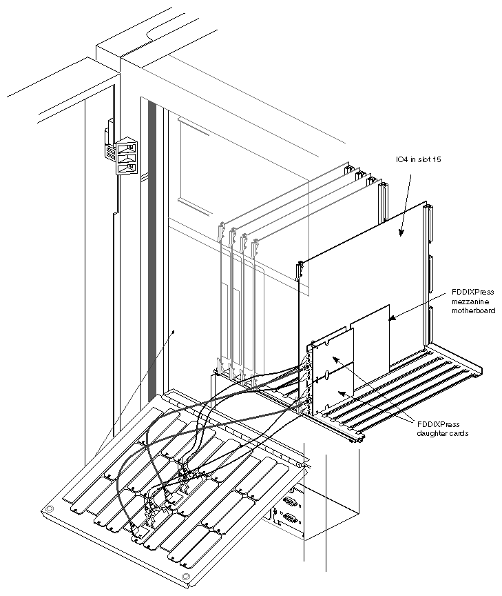
Follow the steps in the appropriate subsection to attach the internal FDDI cables to the board and the panel plates (illustrated in Figure 4-1) to the card cage's I/O panel.
 | Caution: Do not touch the fiber optic material exposed at the ends of the cable. Do not leave the cable ends uncapped. Performance of the fiber optic cable can seriously degrade due to grease or dust. |
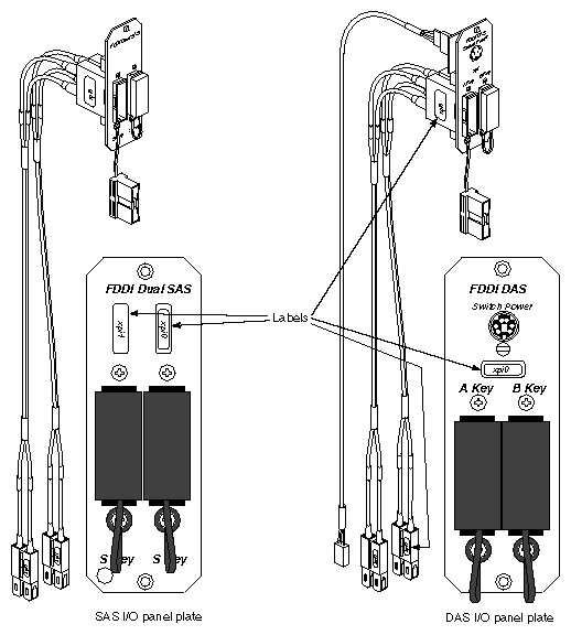
Locate the internal cable assembly. It consists of four fiber optic lines terminated inside two SC-duplex connectors at one end and two MIC receptacles attached to the I/O panel plate at the other end. See Figure 4-1 for an example of the assembly.

Note: For an SAS FDDIXPress installation, the two network interfaces share a single I/O panel plate; each S-key serves a different network connection (interface). Remove one blank panel plate from the system's I/O panel. It is recommended that you do not use the openings nearest the bottom of the I/O door, because the MIC connectors on the FDDIXPress panel plate can make removal of boards difficult.
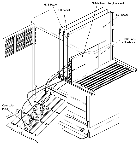
The panel plates for a board in an upper mezzanine slot (adapter 6) should be positioned below the panel plates for a board installed in a lower (adapter 5) slot, as illustrated in Figure 4-4 and Figure 4-5. This positioning evens out the distances over which the internal cables must stretch.
Install the FDDIXPress panel plate. See Figure 4-4 for a deskside example and Figure 4-5 for a rackmount example.
Remove the protective caps from the SC-duplex connectors on the FDDIXPress mezzanine board, if you haven't already done so.
Remove the protective caps from the SC-duplex plugs on the cable assembly.
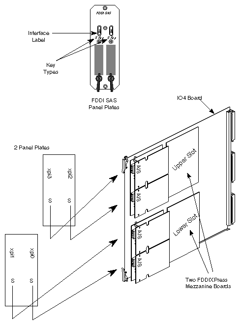
Connect the internal cable assembly to the board's SC-duplex connectors, as illustrated in Figure 4-2. Take care to connect the cable from the left-hand side of the panel plate to the SC-duplex connector that is closest to the top edge of the installed FDDIXPress board; connect the cable from the right-hand side of the panel plate to the bottom-most SC-duplex connector.
To ensure proper orientation, the SC-duplex plug on the cable assembly has guide ridges that must slide into slots in each receptacle.
Go to Section 4.2, "Labeling the Hardware."
Locate the two internal cable assemblies. Each assembly consists of four fiber optic lines terminated inside two SC-duplex plugs at one end and two MIC receptacles attached to the I/O panel plate at the other end. See Figure 4-1 for an example.
Note: For DAS FDDIXPress boards, each panel plate serves one network connection (interface). Remove two blank panel plates from the system's I/O panel. It is recommended that you do not use the openings nearest the bottom of the I/O door, because the MIC connectors on the FDDIXPress panel plate can make removal of boards difficult.
The panel plates for a board in an upper mezzanine slot (adapter 6) should be positioned below the panel plates for a board installed in a lower (adapter 5) slot. as illustrated in Figure 4-4 and Figure 4-5. This positioning evens out the distances over which the internal cables must stretch.
Install the two FDDIXPress panel plates in the I/O door. See Figure 4-4 for a deskside example and Figure 4-5 for a rackmount example.
Remove the protective caps from the SC-duplex connectors on the FDDIXPress mezzanine board, if you haven't already.
Remove the protective caps from the SC-duplex plugs on the cable assemblies.
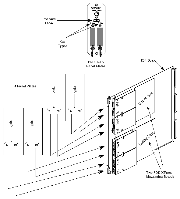
Connect each internal cable assembly to a pair of SC-duplex connectors on the board. To ensure proper orientation, the SC-duplex plug on the cable assembly has guide ridges that must slide into slots in each receptacle.
Connect the cable from the left-hand side of each panel plate (A-key) to a connector labeled A/S-key on the board; connect the cable from the right-hand side of each panel plate to a B-key connector on the board. The two cables from each panel plate must attach to the same daughter card. These connections are illustrated in Figure 4-3.
Connect the two optical bypass switch harnesses to the board and to the panel plates. Take care to attach each OBS harness to the same daughter card as the other cables from that panel plate.
Go to Section 4.2, "Labeling the Hardware."
The sheets of labels provide numerous labels for each FDDIXPress mezzanine network interface. Each FDDIXPress mezzanine board services two network interfaces (for example, xpi0 and xpi1, or xpi2 and xpi3). The labels are intended for identifying the hardware items described in Table 4-1.
Table 4-1. Labels for the Hardware
Hardware Item to Label | Count per | Label Description |
|---|---|---|
For SAS: |
|
|
SC-duplex connectors on board | 2 | 2 large-sized labels for different interfaces (e.g., xpi0 and xpi1). Use one label on each SC-duplex connector. |
SC-duplex plugs on cable assembly | 2 | 2 large-sized labels for different interfaces. Use one label on each SC-duplex plug. |
MIC connectors attached to | 2 | 2 small-sized labels for different interfaces. Use one label on each MIC. |
Network connection ports on | 2 | 2 small-sized labels for different interfaces. Use one label above each S-key port. |
For DAS: |
|
|
SC-duplex connectors on board | 4 | 2 large-sized labels for each interface (e.g., two for xpi0 and two for xpi1). Use one pair of identical labels for each daughter card. |
SC-duplex plugs on cable assembly | 4 | 2 large-sized labels for each interface (4 labels in total). Use one pair of identical labels for each cable assembly. |
MIC connectors attached to | 4 | 2 small-sized labels for each interface (4 labels in total). Use one pair of identical labels for each panel plate. |
Network connection on | 2 | 2 small-sized labels for different interfaces (e.g., one for xpi0 and one for xpi1). Use one label on each panel plate. |
Follow the instructions below to label the hardware for each FDDIXPress mezzanine board:
Use the information in Section 1.5, "Assignment of Network Interfaces to FDDIXPress Mezzanine Hardware," to determine the two network interfaces (for example, xpi0 and xpi1) that the software will assign to each installed FDDIXPress board.
Locate the sheets of labels from the option kit. Identify the two adjacent rows of labels that specify the two network interfaces identified in the previous step.
Remove two sequentially-numbered, large-sized labels to tag the S-key or A/S-key SC-duplex receptacles on the FDDIXPress mezzanine board.
For SAS installations, place the lower-numbered label on the SC-duplex connector nearest the bottom edge of the installed FDDIXPress board, and place the higher-numbered label on the top-most connector.
For DAS installations, place the lower-numbered label on the SC-duplex connector (labeled A/S-key) that is nearest the bottom edge of the installed FDDIXPress board; place the higher-numbered label on the SC-duplex connector labeled A/S-key that is nearer the top edge of the installed FDDIXPress board.
On each daughter card, place a label on the B-key connector that matches the one on the daughter card's A/S-key connector.
Use large-sized labels to tag the cable assembly's SC-duplex plugs that are plugged into the FDDIXPress mezzanine board. Make sure that the labels on the SC-duplex plugs match those on the board's receptacles.
For SAS installations, this step uses two labels.
For DAS installations, this step requires four labels.
Use two small-sized labels to identify the two network interfaces on the outside of the I/O panel plate(s), as illustrated in Figure 4-1.
For SAS installations, place the lower-numbered label (for example, xpi0) above the S-key on the right, and place the higher-numbered label (for example, xpi1) above the key on the left side of the panel plate.
For DAS installations, place the lower-numbered label on the panel plate whose cable is attached to the daughter card nearest the bottom edge of the installed FDDIXPress board; place the higher-numbered label on the panel plate that is attached to the daughter card near the top edge of the installed FDDIXPress board.
Use small-sized labels to identify the MIC connectors that are attached on the internal face of the I/O panel plate.
For SAS installations, this step uses two labels, each identifying a different interface. Make sure the labels on the MICs match those used for that connection on the front of the panel plate.
For DAS installations, this step uses four labels: two labels, identifying the same network interface, for each panel plate. Make sure the two labels on the MICs match the one used on the front of the panel plate.
For each network connection, verify that the lettering (for example, xpi0) on all the installed labels matches. Start at each SC-duplex connector on the FDDIXPress mezzanine board and follow the cabling out to the external face of the I/O panel plate, checking each label along the way. All the labels along each path must have the same lettering.
Additional items, such as external MIC connectors on site cabling, can be labeled also.
Close the I/O door and the chassis door.
Go to Section 4.3, "Connecting External and Site Cabling."
It is recommended that the installation of site (that is, local area network) cabling be performed by a Silicon Graphics approved vendor. Adapter cables, station loopback testers, and other required accessories can also be obtained from these approved vendors. For additional information on approved vendors, contact your Silicon Graphics sales office.
The FDDI connector provided at the FDDIXPress I/O panel plate is a female media interface connector (MIC). For SAS boards, each MIC is an S-key; for DAS installations, each panel plate has an A-key and a B-key. The site's FDDI cables for these ports must be terminated with an appropriate male MIC connector. For SAS installations, a male S-key is appropriate; for DAS FDDIXPress installations, S-, A-, and B-keys are all appropriate).
FDDI MICs each contain two fiber optic lines (an input and an output line). MICs are constructed so that invalid connections are very difficult to make. The connector ridge or cavity (as viewed from the front of the MIC) designates the connector type and mates only with a MIC that results in a valid connection.
Follow these instructions to attach the workstation or server to the FDDI ring:
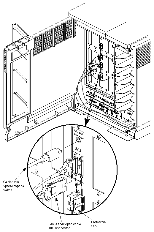
Remove the protective caps from the MICs on the I/O panel plate.
For each FDDI network interface at the system's I/O panel, identify a site FDDI cable for the correct local area network. Be careful to match the interfaces and the local area networks. For example, if you configured (or plan to configure) interface xpi0 with IP address 199.87.5.1, be sure you attach the cable that services the LAN with network address 199.87.5.
Note: Network interfaces do not function if the network portion of the interface's IP address does not match the network address used on the LAN that is physically attached at the I/O panel plate. For DAS installations, you need to identify two MIC connectors for each local area network: an A (or red color-coded) one and a B (or blue color-coded) one.
Attach the site's fiber optic cable. Figure 4-6 illustrates a DAS panel plate; the SAS panel plate, although labeled differently, has a similar layout. The connection should snap (or click) into place.
For DAS installations, connect the site's A MIC to the A-key port on the I/O panel plate and the site's B MIC to the B-key port.
Note: MIC connectors are "keyed" so that they snap into place only when appropriate types are being connected and correct positioning is being used. If the connection does not snap into place, try a different rotation. If that does not solve the problem, verify that the male MIC on the site's cable is the same (or an appropriate) key for the MIC on the panel plate (for example, an I/O panel plate's A-key port can be connected to a male A or S MIC). Go to Section 4.4, "Completing the Installation."
To finish the installation, do the following:
Flip the circuit breaker to ON, then turn the key switch to ON.
When the console prompts you with the question Rebuild the operating system?, answer yes or y in order to build a new operating system (kernel).
Note: If this prompt does not appear, you probably have not installed the FDDIXPress software or a compatible version of the IRIX operating system. Instead of proceeding with the steps below, follow the instructions in the FDDIXPress Release Notes to install and configure the software. If the FDDIXPress network interfaces have not been configured, configure them now. Configuration instructions are provided in the FDDIXPress Administration Guide.
If the xpi network interfaces are already configured, continue to the next step.
Logon and reboot (this is the second time this system is being started) to begin using the newly built operating system. The command lines below can be used to accomplish this step:
% su
Password: thepassword
# reboot
Logon and invoke hinv to verify that the FDDIXPress hardware has been recognized by the software:
% /sbin/hinv
. . .
XPI FDDI controller: xpi#, slot#, adapter#, firmware version#, das/sas
Note: If the FDDIXPress mezzanine board is not listed, any of the following may be the cause: (1) the currently running IRIX does not support this product; (2) the installation has not been done correctly (for example, some board is loose); or (3) the FDDIXPress mezzanine board is dysfunctional. Use the command line below to verify that the xpi network interfaces are configured and enabled:
% /usr/etc/netstat -in
. . .
NAME  Mtu   Network   Address
xpi0  4500  netaddress  IPaddress  ...
xpi1  4500  netaddress  IPaddress  ...
Note: If either of the xpi interfaces has an asterisk after its name or if an address column indicates none, there is something wrong with the configuration. Follow the instructions in the FDDIXPress Administration Guide to reconfigure the FDDIXPress network interfaces. Follow the instructions in Chapter 2 of the FDDIXPress Administration Guide to verify that the FDDI network connections are functioning.
Insertion loss, interconnection loss, and link loss are all factors that must be calculated to determine signal decibel loss within an FDDI local area network.
| Note: The maximum allowable total signal loss is 11 dB between two stations. |
Table 4-2 shows an example of the how to calculate the total signal (power) loss between two DAS stations by summing all the losses from the various sources. On actual installations, the loss values will be different, so it is highly recommended that actual measurements be taken.
The example margin factor shown in the last row of Table 4-2 is derived by subtracting the total calculated signal loss (9.5) from the maximum amount allowed (11 dB). A remainder of 1.5 dB indicates that the signal loss is safely within the limit. Remember, this example shows only possible loss values. To ensure accuracy, you must make actual measurements.
Table 4-2. Example of Power Loss Calculation Between Two DAS Stations
Item | Estimated Power Loss per Item | Number of Instances | Example Loss | Example Margin |
|---|---|---|---|---|
Fiber Loss | 2.5 dB/km | 1 km | 2.5 dB | n.a. |
Splice Loss | 0.2 to 0.5 dB each | 2 | 1.0 dB | n.a. |
Connector Loss | 0.3 to 0.7 dB each | 4 | 2.8 dB | n.a. |
Bypass Control Switch Loss | 2.5 to 3.2 dB each | 1 | 3.2 dB | n.a. |
Total Signal Loss |
|
| 9.5 dB | n.a. |
Maximum Signal Loss Allowed |
|
| 11 dB | n.a. |
Margin Factor |
|
|
| 1.5 dB |