This chapter describes the behavior of the FDDIXPress mezzanine board's light-emitting diodes (LEDs), and provides suggestions for troubleshooting.
The FDDIXPress mezzanine board has 4 LEDs: a pair, one green and one amber, for each FDDI device (connection). Their behavior is described in Table 5-1.
Table 5-1. FDDIXPress Mezzanine LED Behavior
LED | Controlled By | Description |
|---|---|---|
green | firmware | Transmittal/reception: |
amber | firmware | Problem: |
See Section 5.2, "Troubleshooting with LEDs" for in-context combinations of these LEDs.
This section describes procedures for troubleshooting the FDDIXPress mezzanine board.
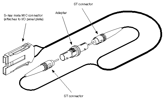
A fiber optic loopback mechanism can be used for troubleshooting a station while it is off the ring. For a single-attachment station (SAS), the mechanism can be either a low-loss loopback station test connector or a loopback cable assembly. Figure 5-1 illustrates a loopback cable assembly designed for a single-attachment station (SAS). The station test connector is the simplest device to use and is sold as an "FDDI station tester." For a dual-attachment station (DAS), the loopback mechanism consists of a section of FDDI cable that terminates in a male A-key and a male B-key MIC connectors.
The LEDs use the following signalling sequences to communicate status information:
 |
Normal operation. The rate of the blinking indicates packet activity (transmission and reception).
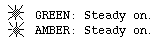 |
The firmware is not functioning. This is normal for the first few seconds after power on or board reset, before the firmware has started to execute. At any other time, this signal indicates that the board is not operational. Perform the following steps to remedy the problem:
Reboot the system to allow the driver to download new firmware onto the board.
As the system starts, look at the messages displayed at the terminal. If any "xpi" messages appear, look them up in the FDDIXPress Administration Guide. As soon as you log on, look in the Syslog file for "xpi" messages.
If the problem persists, reinstall the FDDIXPress software. This step installs a new copy of the file containing the firmware. Use /etc/autoconfig to rebuild the operating system to include the new driver. Then, reboot the system to download the new firmware.
If the problem continues, contact Silicon Graphics Technical Assistance Center.

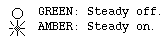
The ring is transitioning from operational to nonoperational. While the amber LED is on, the ring is not operational. The problem may be located at a different station or concentrator. The FDDI ring needs to be verified. If you suspect this station or if you want to verify this station, disconnect it from the ring and verify each FDDI connection, one by one, using the following procedures:
Attach a loopback mechanism to one of the FDDI connections at the FDDIXPress I/O panel plate.
Follow all the instructions in the section "Verifying the FDDI Connection" of the FDDIXPress Administration Guide except those that require the presence of neighbor stations.
Repeat the steps above for each FDDI connection.
The ring is not operational (that is, the ring's state is not RINGOP). This may indicate that the xpi network interface for this FDDI connection is not enabled, or it may indicate a faulty or disconnected cable connection. Perform the following steps:
Stop and restart the xpi network interface associated with this FDDI connection:
# /usr/etc/smtconfig xpi# down up
Use netstat -ina to verify that the xpi network interface is UP and is configured properly. If an asterisk appears next to the interface, it is disabled. Do not proceed until the xpi network interface is configured and enabled.
# /usr/etc/netstat -ina
If the green LED is not blinking, attach a loopback mechanism to isolate the problem. If the green LED blinks when the loopback mechanism is attached, the problem lies with the site's equipment. If the green LED does not blink when the loopback mechanism is attached, the problem is within the FDDIXPress subsystem.
If the problem is isolated to the FDDIXPress subsystem, verify all the cable connections, starting at the board and ending loopback mechanism. Replace any suspect cables with known functional ones.
If the green LED still does not blink, contact Silicon Graphics Technical Assistance Center.
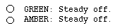
There is no power to the board. Assuming that the rest of the system is functional, this signal may indicate that the FDDIXPress mezzanine board is not firmly seated into the connector on the IO4 board, or that the IO4 board is not seated firmly into the backplane. This signal may also indicate that the FDDIXPress or IO4 board is dysfunctional. Reinstall the hardware, taking extra precautions to seat everything firmly. If the problem persists, contact Silicon Graphics Technical Assistance Center.