This chapter describes how to install the FDDIXPress mezzanine network controller board into a rackmount Challenge or Onyx system. A separate section is dedicated to each type of platform. If you have not already checked and prepared the board, cables, and system software, read Chapter 1.
 | Caution: This product is not customer installable. Installation of this product requires specific training and technical knowledge. These instructions have been provided for use by Silicon Graphics system support engineers or other Silicon Graphics trained or authorized personnel only. This installation requires the installer to handle internal electrical power that is hazardous if the equipment is improperly disassembled or reassembled. |
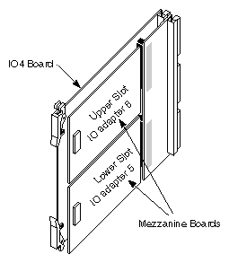
The FDDIXPress mezzanine board is installed onto one of the short mezzanine slots of any IO4 board. Each IO4 board has two mezzanine slots (an upper and a lower), as illustrated in Figure 3-1. The FDDIXPress mezzanine board may be installed on any available short mezzanine slot.
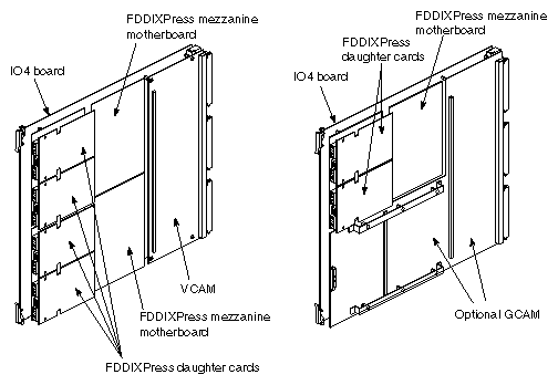
When a system is running Extreme™ Graphics, a GCAM board covers the area on the main IO4 board called the lower mezzanine slot. In this configuration, only one mezzanine slot is available on the main IO4 board. Figure 3-2 shows the difference between a main IO4 board equipped (as normal) with a VCAM and one that has a GCAM.
Use the following guidelines to help determine the best location to physically place the FDDIXPress mezzanine board:
If the system has only one IO4 board, this is the location for the FDDIXPress board.
In all non-Extreme Graphics systems, mezzanine boards may be installed in either the upper or lower position on the IO4 board, as illustrated in Figure 3-2. When both mezzanine locations are available, it is recommended that you use the lower position first.
If the system has more than one IO4 board, you may select any unoccupied mezzanine slot. It is recommended that you use the lower mezzanine slot of the primary IO4 when it is available.
When installing additional FDDIXPress mezzanine boards to a system that already has one or more FDDIXPress mezzanine boards, it is advisable to select a mezzanine slot that is downstream from FDDIXPress mezzanine boards that are already installed. If a new board is installed upstream, the external cables must be moved or the software network interfaces must be reconfigured for the network connections located downstream from the newly installed FDDIXPress mezzanine board.
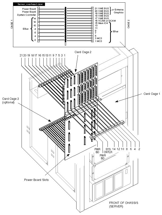
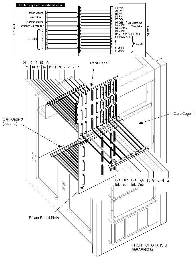
If there are no unoccupied mezzanine slots, you must install another IO4 board. Figure 3-3 and Figure 3-5 illustrate the maximum number and locations for IO4 boards in rackmount chassis.
Contact the sales representative to order one. The installation cannot be continued until a mezzanine slot is available.
Keeping these guidelines in mind, continue to the next section for Challenge XL installation information, or go to the section "Installation Procedures for Onyx Rackmount Systems."
This section describes the steps for installing FDDIXPress into either a POWER Challenge XL or Challenge XL server. The term Challenge is used generically in this section to describe both types of systems.
 | Note: To verify the maximum number of FDDIXPress mezzanine boards supported in a single system, see the FDDIXPress release notes or contact a Silicon Graphics sales office. |
Shut down the system by turning the key on the System Controller panel (located at the front) to OFF.
Wait a minute for the system to shut down, then switch the circuit breaker on the back to OFF.

Warning: Failure to turn off the circuit breaker may result in electrical shock. Failure to wait for the system to shut down may cause irreparable damage to system components or data. Open the rear door and pull down the top I/O panel (cardcage 2) at the rear of the chassis to expose the IO4 boards. The board slots should be visible as illustrated in Figure 3-3.
Verify that you are wearing an electrostatic discharge wriststrap and that you are properly grounded.
Locate the IO4 boards that are currently installed. Slot 15 always has an IO4 board.
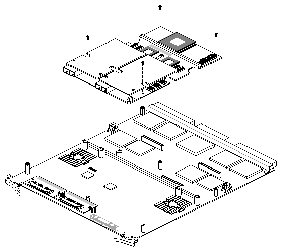
Note: In addition, slots 9, 11, or 13, may contain IO4 boards. A Challenge XL server may have one to four IO4 boards installed. Carefully remove the IO4 board chosen to hold the FDDIXPress mezzanine board, and position it on a flat antistatic work surface, as illustrated in Figure 3-4.
Place the FDDIXPress mezzanine board onto the selected IO4 mezzanine position so that the connector on the bottom of the motherboard matches the receptacle on the IO4 board and the standoffs match the holes in the FDDIXPress board (see Figure 3-4).
Press down on the mezzanine board so that its connector seats into the IO4 board connector.
Use the screws from the FDDIXPress kit to fasten the board. (Common pan-head mezzanine screws do not work for this installation.) The IO4 board's standoffs have a "float" feature, so the mezzanine board's position is somewhat adjustable even after the screws are tightened.
Remove the dust caps from the fiber optic receptacles (ODLs) on the FDDIXPress mezzanine board.
Note: The connector tips for fiber optic cabling are extremely sensitive to oil, dirt, and dust. Never touch the inside tip of an FDDI connector, and do not leave FDDI connectors uncapped when they are not connected. Reinstall the IO4 board into the chassis. Push the board firmly into the backplane.
Note: If you removed board lock bars in order to install this product, do not reinstall them.Board lock bars cannot be used with the product. Go to Chapter 4 for internal and external cabling instructions.
This section describes the steps for installing FDDIXPress into either a POWER Onyx or Onyx rackmount system. The term rackmount Onyx is used generically in this section to describe both types of systems.
| Note: To verify the maximum number of FDDIXPress mezzanine boards supported in a single system, see the FDDIXPress release notes or contact a Silicon Graphics sales office. |
Shut down the system by turning the key on the System Controller panel (located at the front) to OFF.
Wait a minute for the system to shut down, then switch the circuit breaker on the back to OFF.
Warning: Failure to turn off the circuit breaker may result in electrical shock. Failure to wait for the system to shut down may cause irreparable damage to system components or data. Open the front door and pull down the I/O panel in the front of the chassis to access the IO4 board. The board slots should be visible, as illustrated in Figure 3-5.
Verify that you are wearing an electrostatic discharge wriststrap and that you are properly grounded.
Locate the IO4 boards that are currently installed. Slot 11 (in cardcage 2) always holds the primary (main) IO4 board in a rackmount Onyx system.
Carefully remove the IO4 board chosen to hold the FDDIXPress mezzanine board, and position it on a flat antistatic work surface, as illustrated in Figure 3-4.
Place the FDDIXPress mezzanine board onto the selected IO4 mezzanine position so that the connector on the bottom of the motherboard matches the receptacle on the IO4 board and the standoffs match the holes in the FDDIXPress board, as illustrated in Figure 3-4.
Press down on the mezzanine board so that its connector seats into the IO4 board connector.
Use the screws from the FDDIXPress kit to fasten the board. (Common pan-head mezzanine screws do not work for this installation.) The IO4 board's standoffs have a "float" feature, so the mezzanine board's position is somewhat adjustable even after the screws are tightened.
Remove the dust caps from the fiber optic receptacles (ODLs) on the FDDIXPress mezzanine board.
Note: The connector tips for fiber optic cabling are extremely sensitive to oil, dirt, and dust. Never touch the inside tip of an FDDI connector, and do not leave FDDI connectors uncapped when they are not connected. Reinstall the IO4 board into the chassis. Push the board firmly into the backplane.
Note: If you removed board lock bars in order to install this product, do not reinstall them.Board lock bars cannot be used with the product. Go to Chapter 4 for internal and external cabling instructions.
The optional optical bypass switch (OBS) maintains the integrity of the ring in the event that the attached system becomes dysfunctional or is powered down. To install an OBS, see the installation instructions that accompany the OBS. Note that only an FDDIXPress mezzanine board with dual-attachment (DAS) connections can use an optical bypass switch.
The optional optical bypass switch is ordered as a separate kit. Contact the customer's Silicon Graphics salesperson for details.