This chapter discusses important preparations to make before installing the FDDIXPress mezzanine board for Challenge and Onyx deskside and rackmount products.
Discussion of the FDDIXPress mezzanine board's general operational characteristics and hardware is also included.
 | Warning: Installing this equipment requires specific training and technical knowledge. These instructions are provided for use only by Silicon Graphics system support engineers (SSEs) or other service personnel trained or authorized by Silicon Graphics. This equipment uses internal electrical power that is hazardous if the equipment is improperly handled. |
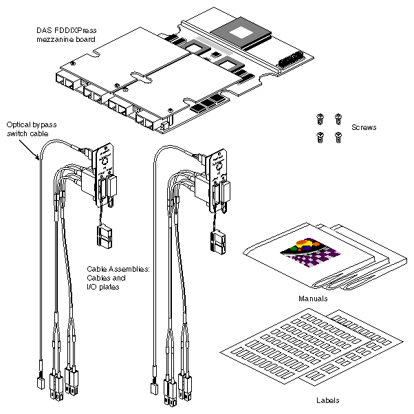
Verify that the FDDIXPress mezzanine option package is complete. For the single-attachment station product (SAS), the package should contain the items listed in Table 1-1 and illustrated in Figure 1-1. For a dual-attachment station product (DAS), it should contain the items listed in Table 1-2 and shown in Figure 1-2. If anything is missing, and you cannot properly complete the installation, notify the customer or the customer's salesperson.
Table 1-1. SAS FDDIXPress Mezzanine Package Contents
Item | Part Number | Quantity |
|---|---|---|
FDDIXPress short mezzanine board with two SC™-duplex connectors | 013-0963-00v[a] | 1 |
Internal fiber optic cable assembly (terminated in two S-key connectors) | 013-0967-00v | 1 |
Hardware set to attach the FDDIXPress mezzanine board to the IO4 board | 026-0997-00v | 1 |
FDDIXPress mezzanine label sheets | 024-0844-00v | 1 |
FDDIXPress Mezzanine Board for Challenge and | 108-0116-002 | 1 |
FDDIXPress Administration Guide | 007-0813-0vv | 1 |
FDDIVisualyzer User's Guide | 007-0814-0vv | 1 |
[a] The version numbers (v) change from release to release. | ||
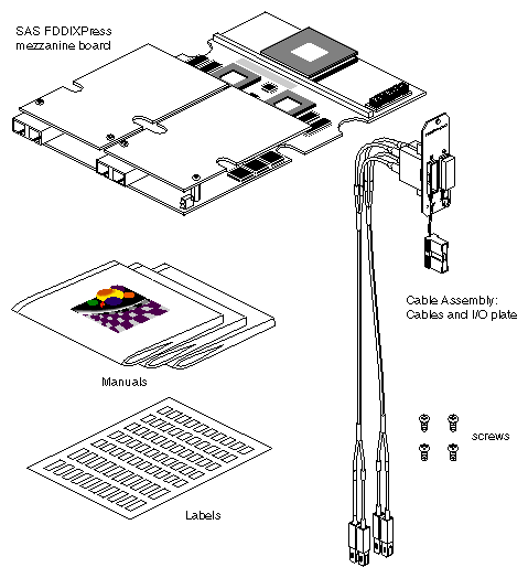
Table 1-2. DAS FDDIXPress Mezzanine Package Contents
Item | Part Number | Quantity |
|---|---|---|
FDDIXPress short mezzanine board with four SC-duplex connectors | 013-0964-00v[a] | 1 |
Internal fiber optic cable assembly (terminated in A- and B-key connectors) | 013-0968-00v | 2 |
Hardware set to attach the FDDIXPress mezzanine board to the IO4 board | 026-0997-00v | 1 |
Optical bypass switch power harness | 015-0231-00v | 1 |
FDDIXPress mezzanine label sheets | 024-0844-00v | 2 |
FDDIXPress Mezzanine Board for Challenge and | 108-0116-002 | 1 |
FDDIXPress Administration Guide | 007-0813-0vv | 1 |
FDDIVisualyzer User's Guide | 007-0814-0vv | 1 |
[a] The version numbers (v) change from release to release. | ||
Before starting the installation, prepare yourself and the equipment by following the instructions in this section.

Use the following steps to confirm that the system is running the proper software releases, and that files are properly backed up before bringing down the system. Some releases of FDDIXPress software are compatible only with specific versions of the operating system (IRIX™), and most FDDIXPress hardware operates only with versions of the FDDIXPress software that equal or post-date a particular version.
Use the versions command to check if the system into which you are installing the FDDIXPress mezzanine board is already running FDDIXPress software. If FDDIXPress is not installed, install it now.
% versions FDDIXPress
I FDDIXPress date FDDIXPress, version

Note: Software for IRIX and FDDIXPress is normally located on the same CDROM. Read the online FDDIXPress release notes to verify that this version of FDDIXPress supports the mezzanine board for Challenge and Onyx.
% grelnotes FDDIXPress
If the release notes do not mention the mezzanine board for Challenge and Onyx, you need to locate and install an appropriate version of FDDIXPress software, and possibly a new IRIX operating system. See the IRIX Software Installation Guide for complete instructions for installing new software.
Note: FDDIXPress 3.6 and IRIX 5.3 are the first releases to support the FDDIXPress mezzanine board for CHALLENGE and Onyx. Confirm that the installed IRIX operating system is compatible with this version of FDDIXPress software. The FDDIXPress release notes contain information about version compatibility. If necessary, install a new version of the IRIX operating system. Complete instructions for this procedure are provided in the IRIX Software Installation Guide.
% versions eoe1
I eoe1 date IRIX Execution Environment 1, version
Verify that the file systems are backed up.
Configure the two (or more) new FDDIXPress network interfaces (xpi0, xpi1, and so on) that upon boot up will be associated with the hardware you are about to install. Instructions for this configuration task are provided in the FDDIXPress Administration Guide that is included in the FDDIXPress package.
Note: If you do not configure the FDDIXPress network interfaces now, the configuration can be done immediately after powering on the system (following the hardware installation).
Observe the following precautions whenever handling or installing FDDI equipment:
Fiber optic cable is made of glass and is, therefore, breakable. Do not overly bend, flex, or tug on a fiber cable. The smallest recommended bend radius of a cable is 2 inches. Do not allow the cable to be struck sharply or by heavy objects.
The connector tips for fiber optic cabling are extremely sensitive to oil, dirt, and dust. Never touch the inside tip of an FDDI connector, and do not leave FDDI connectors uncapped when they are not connected.
The FDDIXPress mezzanine board and the computer equipment are extremely sensitive and susceptible to damage caused by electrostatic discharge (ESD). ESD is a spark caused by the build-up of electrical static potential on clothing and other materials. You must use proper ESD preventive measures and also the precautions listed below:
Connect a ground strap to your wrist when connecting or disconnecting peripherals.
Be sure that you and all the electrical equipment that you handle during this installation are at ground potential.
Keep the boards in the antistatic bags provided, and remove a board from its antistatic bag only when you are properly grounded to the chassis with a ground strap.
Table 1-3 describes the connectors on FDDIXPress mezzanine boards. Table 1-4 describes the connections provided at the I/O panel plate (bulkhead).
Table 1-3. FDDIXPress Board Connector Descriptions
Connector's | Count | Function |
|---|---|---|
DAS Board: |
|
|
A/S-key | 2 | Provides a duplex-wire connection to an A port at the bulk head (panel plate). This connector is an SC-duplex type. |
B-key | 2 | Provides a duplex-wire connection to a B port at the bulk head (panel plate). This connector is an SC-duplex type. |
OBS | 2 | Provides control line and power to the optical bypass switch (OBS) connector at the bulkhead (panel plate). |
SAS Board: |
|
|
A/S-key | 2 | Provides a duplex-wire connection to an S port at the bulk head (panel plate). This connector is an SC-duplex type. |
Table 1-4. FDDIXPress Panel Plate Connector Descriptions
Connector's | Count per Panel Plate | Function |
|---|---|---|
DAS Panel Plates: |
|
|
A-key | 1 | Provides an A or S connection to the FDDI local area network. This connector is a MIC type. For a dual-attached station (port connected to a site cable A-key), the port consists of the primary ring input and secondary ring output. For a single-attached station (port connected to a site cable S-key), the port consists of the input and output lines between the station and the concentrator's M port. If both the A and B ports are attached to concentrators (dual-homed), the connection at the A-key port acts as the backup. |
B-key | 1 | Provides a B or S connection to the FDDI local area network. This connector is a MIC type. For a dual-attached station (port connected to a site cable B-key), the port consists of the primary ring output and secondary ring input. For a single-attached station (port connected to a site cable S-key), the port consists of the input and output lines between the station and the concentrator's M port. If both the A and B ports are attached to concentrators (dual-homed), the connection at the B-key port acts as the main connection to the ring. |
OBS | 1 | Provides control line and power to the optical bypass switch (OBS). The OBS is available with DAS only, and is optional. |
SAS Panel Plate: |
|
|
S-key | 2 | Provides an S connection to the fiber optic cable between the SAS station and a concentrator's M port. This connector is a MIC type. The port consists of the input and output. |
As you install the FDDIXPress mezzanine hardware, you need to anticipate the network interface that will be assigned (by the software) to each FDDI connection during the subsequent boot procedure. The guidelines below describe the algorithm used by the software:
Each IO4 board is probed for the presence of an FDDIXPress board. The IO4 boards are probed in the following order:
Main IO4, lower mezzanine slot (adapter 5)
Main IO4, upper mezzanine slot (adapter 6)
Second IO4 board, lower mezzanine slot (adapter 5), then upper slot (adapter 6)
The probe continues in this fashion, until all IO4 boards have been probed
The located FDDIXPress boards are assigned interfaces in the order that the boards were found. Each board is assigned two network interfaces. That is, the first FDDIXPress board found is assigned xpi0 and xpi1, and the second board is assigned xpi2 and xpi3.
The FDDI connection located on the daughter card nearest the bottom edge of the FDDIXPress mezzanine board (as the board appears when installed in the card cage) is assigned the lower-numbered interface of the assigned pair (for example, xpi0 or xpi2).
The FDDI connection located on the daughter card nearest the top edge of the FDDIXPress mezzanine board (as the board appears when installed in the card cage) is assigned the higher-numbered interface of the assigned pair (for example, xpi1 or xpi3).
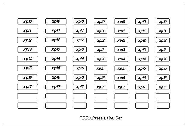
SC-duplex connectors on the board, I/O panel plates, and cables can be labeled for easier identification, using the labels that are included in the option kit. Figure 1-3 illustrates a sheet of labels. These labels indicate the software network interface that you expect to be associated with each item. For example, the small-sized labels xpi0 and xpi1 are designed for labeling the two panel plates on a system with one DAS board or the two S-key ports on the single panel plate of an SAS board. Section 4.2, "Labeling the Hardware," describes where to install these labels.
This section describes the architecture, the main features, and the physical characteristics of the FDDIXPress mezzanine product.
The FDDIXPress mezzanine board processes the transmission and reception of data packets (frames) across two independent 100-megabit-per-second FDDI networks. The board occupies one short mezzanine slot on any IO4 board. The board can be ordered as a single-attachment (SAS) or dual-attachment (DAS) FDDI board.
For detailed information on the FDDI standard and its operation, see the FDDIXPress Administration Guide, included in the FDDIXPress package.
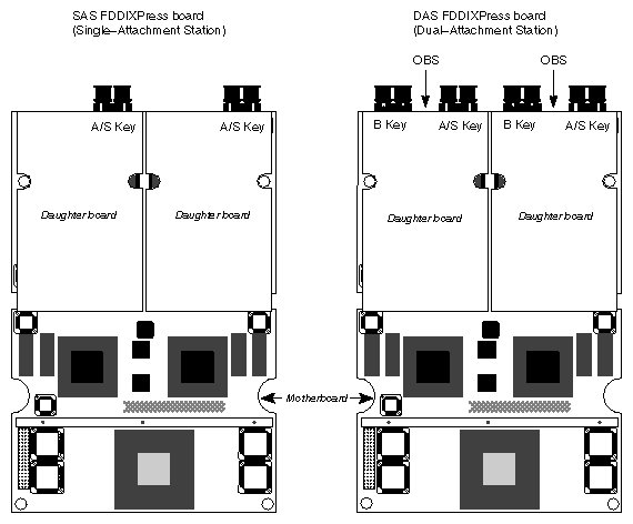
Each FDDIXPress mezzanine board consists of a motherboard and two daughter boards. The daughter board determines whether the physical network connection supports single-attachment (SAS) or dual-attachment (DAS). Figure 1-4 shows the daughter board configurations for both the SAS and DAS products.
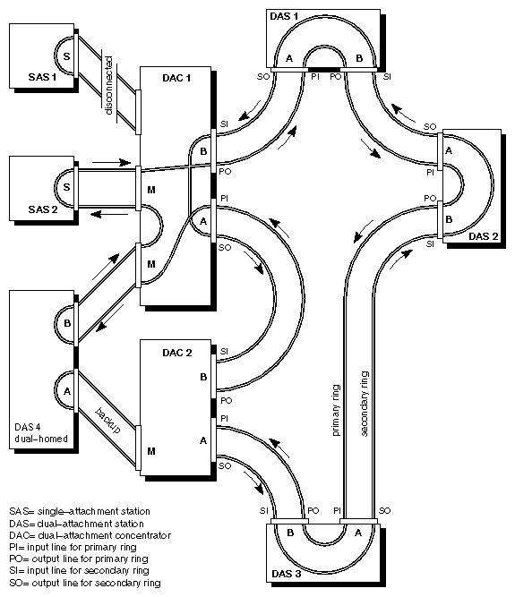
Each FDDIXPress mezzanine board (SAS or DAS) provides two independent network connections (two Media Access Control [MAC] addresses and two software interfaces) that can access two different FDDI local area networks (rings) or can provide two independent connections to the same FDDI ring. The single-attachment board accesses its ring(s) through concentrators. The dual-attachment board connects directly to the ring(s), and each interface is capable of wrapping in order to maintain communication in the event of a break (as illustrated in Figure 1-5 and Figure 1-6). On a dual-attachment board, either one or both of the FDDI interfaces can be used as a single-attachment connection, a dual-homed single-attachment connection, or a dual-attachment connection.
| Note: A dual-homed FDDI connection attaches port A to one concentrator on the FDDI ring and port B to a different concentrator on the same FDDI ring. The port B connection functions as the main connection, while port A is the backup (inactive until the port B connection fails). |
The motherboard communicates with the host (local system) through the IBus™ (also known as HIO) of any standard IO4 board. The Silicon Graphics DANG™ ASIC, on the motherboard, interfaces between the Challenge or Onyx system's IBus (on the IO4 board) and the FDDIXPress mezzanine board's GIO Bus™.
The architecture of the FDDIXPress mezzanine board focuses on the efficient sharing of the central 256-kilobyte high-speed SRAM resource. The SRAM resources are shared by three local bus masters: GIO Bus, on-board microprocessor, and FDDI interface chip set.
The on-board processor initializes and controls registers within the FDDI chip set and the DANG chip (host system), as well as manipulates and inspects data in the SRAM. The GIO Bus interface, either as the master or the slave, has the ability to request information and give commands to the processor. The GIO Bus can also transfer data between the SRAM and system memory. The FDDI chip set, as a local bus master only, requires data transfers between the SRAM and the chip set's own internal buffers.
The main features of the FDDIXPress mezzanine board are listed below:
Provides two completely independent, single-MAC FDDI interfaces
Comprises an AMD® 29030 RISC processor and the Motorola® FDDI chip set
Includes 256 kilobytes of on-board, custom buffer memory
Provides full FDDI performance on each FDDI interface, simultaneously[1]
Offers dual-attachment (DAS) and single-attachment (SAS) versions of the product
The DAS FDDIXPress board supports an optional external optical bypass switch at each FDDI interface
The motherboard has the following components:
AMD 29030 RISC processor
GIO Bus logic, supporting both master and slave operations
DANG chip to interface between mezzanine board's GIO Bus and IO4 board's IBus
128 kilobytes of EEPROM and 256 kilobytes of fast static RAM
Two sets of FDDI logic, supporting two independent FDDI interfaces. Each set includes the following items:
A connector to attach one of the daughter boards
A portion of the FDDI interface, implemented using the Motorola® MC6883x FDDI chip set. The components that reside on the mother board are the following:
MC68838 MAC chip
MC68839 FSI chip
Each daughter board supports one FDDI interface with the following components and supporting logic:
The remaining portions of the FDDI interface, implemented with the Motorola MC6883x FDDI chip set. The Motorola components that reside on the daughter board are the following:
- MC68837 ELM chip: one for SAS; two for DAS
- MC68836 FCG chip: one for SAS; two for DAS
The direct fiber connection, provided by integrated fiber optic transmission and receive devices, referred to as ODLs: one ODL for SAS, two ODLs for DAS.
The physical characteristics and specifications for the FDDIXPress mezzanine board are summarized in Table 1-5.
Table 1-5. Board Specifications
Specifications | Value |
|---|---|
Mechanical | Mezzanine board mounted to IO4 |
Maximum number of FDDIXPress mezzanine boards per system | Two [a] |
Power consumption | 7.0 amps of +5 VDC |
System operating temperature | 0-35 degrees centigrade |
Operating humidity | 0-90% (noncondensing) |
[a] This may change in future releases. The online FDDIXPress release notes contain current information. | |
This section illustrates some of the more important FDDI terms and concepts. Figure 1-5 illustrates an FDDI dual ring with a variety of types of stations: dual-attachment, single-attachment, dual-homed, and concentrators. Figure 1-6 shows a how a ring wraps when there is a break.
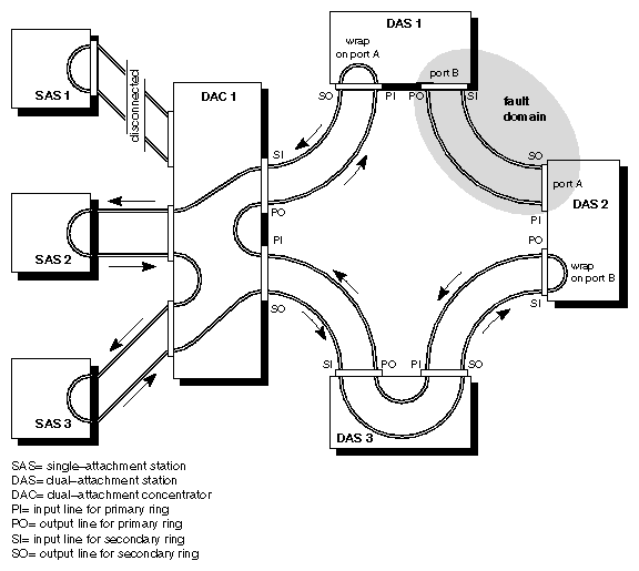
The break that is causing the fault domain illustrated in Figure 1-6 could be a dysfunction of any of the following:
the cable lying between DAS1 and DAS2
the output connector for the primary ring (PO, one line of port B) at DAS1
the input connector for the primary ring (PI, one line of port A) at DAS2
a component on the FDDI controller board for transmitting at DAS1 or for receiving at DAS2 on the primary ring
Notice that a dysfunctional SAS (illustrated by SAS1 in both Figure 1-5 and Figure 1-6) does not cause the ring to wrap.