The power subsystem consists of the offline switchers (OLSs), the midplane and backplane power buses, the DC-to-DC converters (power bricks) on the Everest CPU, VCAM, and memory boards, and the various power boards. The following power boards can be installed: 505 (Cardcage 3 only), 512, dual 505 (also known as the 505x2), 512S (in the SCSIbox 2), and System Controller. See Figure 3-1 for a block diagram illustrating the power subsystem components.
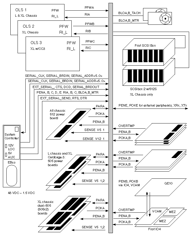
When the system is turned on, the power subsystem goes through a series of voltage checks before the boot process is allowed to start. Power is applied to the various system components in the following order: +/-5 V and +/-12 V power bricks (power for the SCSI drives in the deskside systems), 1.5 V and 3.3 V power bricks, 5 V and 12 V power bricks (power for the first internal SCSIBox in the rackmount systems), and 5 V and 12 V for external SCSI. This power sequencing is designed to prevent component damage due to incorrect or missing voltages, and to avoid placing a large transient demand on the voltage source.
There are only three diagnostic tools at this point in the system's start-up sequence: the red fault LEDs on each circuit board, the AC voltage input and DC voltage output LEDs on each OLS, and the System Controller. To effectively use these indicators to troubleshoot a system fault, refer to the fault indicator descriptions and the power-up sequence described in the following sections.
This section describes the power fault indicators found on each system and power board, on each OLS, on the SCSIBox backplane, and on the system Status Panel. The locations of the power fault indicators, the power bricks, the removable fuses, and the secondary regulators (where applicable) are also shown.
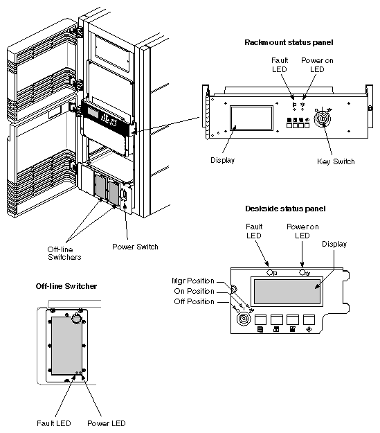
Two LEDs are located above the System Controller function buttons (see Figure 3-2). The green power-on LED lights to indicate that 48 volts is present at the system midplane/backplane, and remains lit as long as 48 volts are present. The amber fault LED lights briefly during the power-up sequence, but should go out when the power-on tests are complete.
Each OLS also has a green and an amber LED. The amber LED lights to indicate that the AC input voltage level is within acceptable levels. The green LED lights to indicate that the DC output voltage levels are within acceptable levels. Both LEDs should remain lit during normal system operation.
This section provides the locations of the power fault indicators on each of the system and power boards.
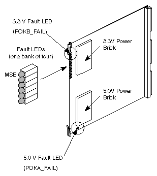
The IP19 and IP21 boards have two power bricks that step down the 48 volts from the midplane/backplane to 5.0 and 3.3 volts. Each brick has a corresponding power fault LED, as shown in Figure 3-3.
 | Note: The LEDs are red and indicate a fault when lit. |
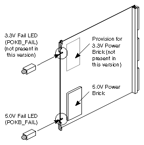
The MC3 board currently has a single +5.0-volt power brick, and a corresponding fault indicator. Later versions of this board may have an additional +3.3 volt brick, as shown in Table 3-1 and Figure 3-4.
| Note: The LEDs are red and indicate a fault when lit. |
Table 3-1. MC3 Board Fault LEDs
LED Reference Designation | Color / Meaning | Description |
|---|---|---|
N8P2 (POKB_FAIL) | Red/Fault | Bad 3.3 V power brick |
B4P2 (POKA_FAIL) | Red/Fault | Bad 5.0 V power brick |
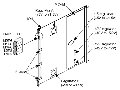
The IO4 board has a single bank of five LEDs and two secondary regulators. These regulators convert +5 volts to +1.5 volts (see Table 3-2 and Figure 3-5). The IO4 also has three replaceable fuses, as shown in Figure 3-5.
The VCAM board three secondary regulators: +1.5, -12, and -5.2 volts.
| Note: All LEDs are red and indicate a fault when lit. The bottom three LEDs provide power fault indications for the attached VMEbus Channel Adapter Module (VCAM). The VCAM fault LEDs are mounted on the IO4 board because the dimensions of the VCAM would make on-board LEDs extremely difficult to read. These LEDs are unlit when no VCAM is installed. |
Table 3-2. IO4 Board Fault LEDs
LED Reference Designation | Color / Meaning | Description |
|---|---|---|
M2P6 (POKB_FAIL) | Red/Fault | Bad 1.5 V regulator A (near top) on the IO4 board |
M1P6 (POKB_FAIL) | Red/Fault | Bad 1.5 V regulator B (near bottom) on the IO4 board |
M0P6 (POKB_FAIL) | Red/Fault | Bad 1.5 V regulator on the VCAM |
L9P6 (POKA_FAIL) | Red/Fault | Bad -12 V to -5.2 V regulator on the VCAM |
L8P6 (POKA_FAIL) | Red/Fault | Bad +12.0 V to -12.0 V regulator on the VCAM |
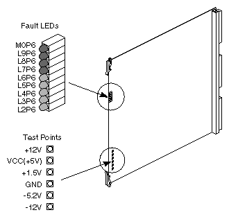
The RMT_VCAM board has a bank of nine fault LEDs that flag power faults stemming from the Cardcage 3 backplane, the System Controller, and the three regulators on the RMT_VCAM itself. There are also six test points corresponding to the monitored voltages (see Table 3-3 and Figure 3-6).
| Note: The voltage levels of the three on-board voltage regulators are monitored by two sets of LEDs: the three red LEDs and the bottom three amber LEDs. The red LEDs light when a voltage error is sensed and remain lit until the system is reset. The amber LEDs provide a "hot" measurement and light only when an error is present in the monitored voltage levels. |
Table 3-3. Remote VCAM Fault LEDs
LED Reference Designation | Color / Meaning | Description |
|---|---|---|
M0P6 | Red/Fault | Bad +1.5 V regulator on the RMT_VCAM |
L9P6 | Red/Fault | Bad -5.2 V regulator on the RMT_VCAM |
L8P6 | Red/Fault | Bad -12 V regulator on the RMT_VCAM |
L7P6 | Green/Good | 5 V input (V5_AUX) from System Controller to RMT_VCAM (should always be on) |
L6P6 | Amber/Fault | Bad +12 V input from the backplane |
L5P6 | Amber/Fault | Bad +5 V input (VCC) from the backplane |
L4P6 | Amber/Fault | Bad +1.5 V regulator on the RMT_VCAM |
L3P6 | Amber/Fault | Bad -5.2 V regulator on the RMT_VCAM |
L2P6 | Amber/Fault | Bad -12 V regulator on the RMT_VCAM |
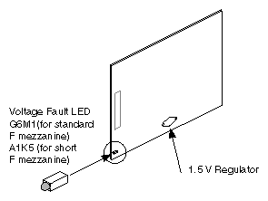
Both F mezzanine cards (F Mezz and Short F Mezz) have a 5 V-to-1.5 V regulator, identical to those on the IO4 and VCAM. Each F mezz board also has a single, red voltage fault LED, as shown in Figure 3-7. The LED lights when the voltage level is out of range.
The S mezzanine card (not shown) has no regulators, but has three removable fuses.
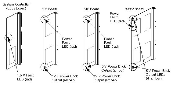
The are five different power boards that can be installed in the Challenge/Onyx deskside and rackmount systems: the System Controller, 505, 505x2, 512, and 512S. Each board has one or more power fault LEDs. Figure 3-8 shows power-fault LEDs for the System Controller, 505, 505x2, and 512 boards.
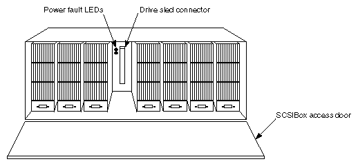
There is a +5 V and a +12 V power LED located behind each drive in the SCSIBox. Both LEDs are green and are lit during normal operation (see Figure 3-8).
| Note: The power switch (main circuit breaker), located in the lower right corner of the front of the system cabinet, must be turned on. |
Turning the System Controller key switch to the On or Manager position enables the OLSs to output 48 volts to the midplane/backplane. The green power-on LED, above the front panel display, lights to indicate that voltage is present at the midplane/backplane. The step-down regulator on the System Controller power board converts the 48 volts to 5.0 volts (V5_AUX) for use by the System Controller, power brick control circuits, and LEDs. As the System Controller powers up and begins its initialization, the amber fault LED above the display lights. When the System Controller successfully initializes and the power-on tests are complete, the amber fault LED goes out.
| Note: If the system will not power up (green front panel LED not lit), first check the LEDs on each of the offline switchers. If the OLSs do not indicate a fault, verify that there are 48 volts at the backplane near the power-on LED. If the backplane voltage is correct, but the System Controller has not initiated the power sequencing, first check the display for an error message, then check the System Controller board and verify that the 5.0 V VS_AUX line from the System Controller is supplying power to the power bricks. |
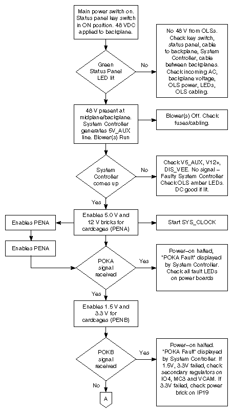
The System Controller then manages the power sequencing for the rest of the system. A series of power-enable (PENx TTL_H) signals are asserted in the following sequence:
PENA: controls +5.0, -5.2 and +/-12 volts
PENB: controls 1.5, 1.6 (System Controller termination voltage), and 3.3 volts
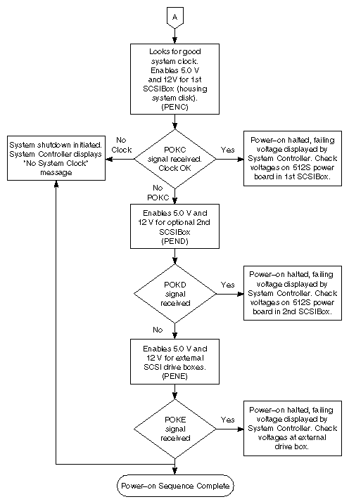
PENC: controls 5 and 12 volts for the first SCSIBox housing the system disk (rackmount systems only)
PEND: controls 5 and 12 volts for the optional, second SCSIBox (rackmount systems only)
PENE: controls 5 and 12 volts for any external cabinets
Each time a signal is asserted, a corresponding power-OK (POKx) signal is tested, indicating to the System Controller that the voltage levels are correct. If any voltage-enable line does not generate an OK signal, the System Controller will stop the power-on sequence at the point of the failure. The POKx signals are continually monitored during and after power up. Any POKx signal going low indicates a power-fail condition at one or more of the system power supplies/regulators. A low POKx signal (except POKE) causes the System Controller to display a "Power Fault" message and begin the system power-off sequence.
In the case of a fault following the assertion of PENE, the POKE line is asserted 30 seconds later. The system treats this signal as a warning and does not begin the power-off sequence.
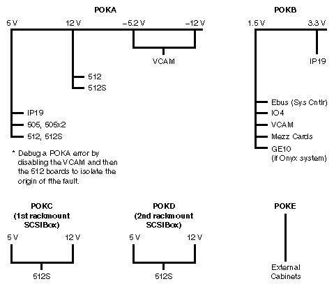
Figure 3-10 illustrates the relationship of the POKx signals to the various system voltages and components. The system power-on sequence is illustrated by the flowchart in Figure 3-11 through Figure 3-12.
When the system has successfully powered up, the System Controller deasserts the power clear (PCLR) and system clear (SCLR) signals to the address ASIC on each CPU board. The cache controllers then reset each of the system's processors and the power-on tests are started. (Power-on tests are described in Chapter 5, "PROM Monitor.")
See Figure 3-13 for the power-enable/power-ok signal timing. Note that the enable signals are PENx (TTL_H), and that the fault signals are POKx (TTL_L).
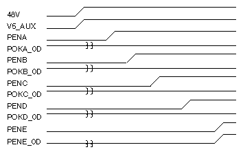
| Note: The POKx signals (with the exception of POKE) remain high unless there is a fault. The System Controller checks for a low TTL signal to indicate a failed POK problem. |
With the key switch in the Manager position, the voltage status menu can be called up on the Status Panel. This menu displays the actual voltages at the midplane/backplane, at the power boards, and at the VCAM. The voltage status menu is shown in .
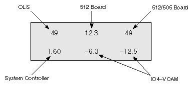
If an out-of-range voltage level is sensed on either the midplane/backplane, 505, or 512 power boards, the System Controller will display a message indicating which voltage is out-of-range and whether it is high or low. The display indicates which voltage level failed, but cannot isolate the failure to an individual power board because same-level voltages are ganged together.
The power-OK (POK) signals also cannot isolate a voltage fault to a specific component. The voltages at each power brick are monitored, but the power-OK lines (POKA, B, C...) are all OR-tied together, so a failure sensed by any of the POK lines indicates the failing voltage but cannot isolate the specific FRU. Also, in systems with more than one of each type of power board, identical voltages are ganged together. Finally, there are secondary regulators; one on the backplane, two on the IO4 board, one each on the MC3 and VCAM boards, and one on each of the FMezz boards, whose output voltages are only POKed.
A voltage fault is isolated by inspecting the fault LEDs on all of the suspect boards before powering down or resetting the system (refer to the tables in the following section for the LED error codes). Check the system for a lit POKx LED when either a voltage fault message (such as 5 V low fault) or a POK error message (such as POKx bad) is displayed. The points where the voltages are monitored are shown in .
If a CPU, blower, voltage regulator, or power brick fails, the System Controller will disable the bricks but will leave 48 volts at the midplane/backplane and the V5_AUX on. V5_AUX allows all of the fault LEDs to remain lit and provides power to the Status Panel and System Controller. If a shutdown has occurred, check the error message that is displayed and visually inspect the corresponding fault LEDs throughout the system to isolate the fault. See Section 3.2, "Power Fault Indicator Descriptions and Locations" for the locations of the fault LEDs, and Section 3.3, "Power-On Sequence," for the System Controller error messages.
| Note: Check the Status Panel for error messages and inspect the cardcage(s) for lit fault LEDs before restarting the system. Repeated power cycling during fault diagnosis will eventually fill the System Controller event history log and overwrite the original error message. The bootmaster CPU can save the contents of the System Controller history log in /usr/adm/SYSLOG only after the boot process is complete. If the fault prevents the system from booting, there will be no record of the fault in UNIX. |
If any over-temperature fault occurs, the entire system shuts down. Isolate the fault by restarting the system with the key switch and checking the error message on the front panel display. If the temperature sensors are not given sufficient time to cool below the trip point, the system will continue to shut down. Temperature sensors are located on the CPU (IP19 and IP21), MC3, 512S, and IO4 boards, as well as on the backplane/midplane. See Section 4.2.5.1, "Overtemperature Faults" for additional information about over-temperature faults.
See Figure 3-15 for a diagram illustrating the power subsystem voltage monitoring.
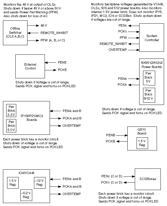
The System Controller monitors the midplane/backplane voltages: +1.5, +5, +12, -5.2, -12, and 48 volts. Any voltage out of the specified range is recorded in the history file and the system shut down. A warning is issued to the operating system (IRIX) and logged in the system controller log for voltage levels approaching out-of-spec levels.
Table 3-4 provides the voltage ranges monitored by the System Controller, and two sets of voltage thresholds: the upper and lower thresholds at which a voltage warning is issued, and the upper and lower thresholds at which the system is shut down.
Table 3-4. Voltage Ranges and Warning Thresholds
Maximum Undervoltage[a] | Warning[b] | Nominal | Warning[c] | Maximum Overvoltage[d] |
|---|---|---|---|---|
45 V | ----------- | 47.49 V | ----------- | 54 V |
10.2 V | 10.97 V | +12.2 V | 13.02 V | 14.3 V |
4.35 V | 4.59 V | +5.15 V | 5.46 V | 5.85 V |
1.05 V | 1.23 V | +1.5 V | 1.77 V | 1.99 V |
-3.63 V | -4.4 V | -5.4 V | -5.66 V | -6.05 V |
-8.45 V | -10.0 V | -12.8 V | -13.7 V | -14.5 V |
[a] Below this voltage the system shuts down. [b] Below this voltage a warning is issued. [c] Above this voltage a warning is issued. [d] Above this voltage the system shutdown. | ||||
| Note: The POK signals are asserted at the undervoltage limits. If a specific test circuit fails to assert POK, the System Controller initiates a system shutdown. |