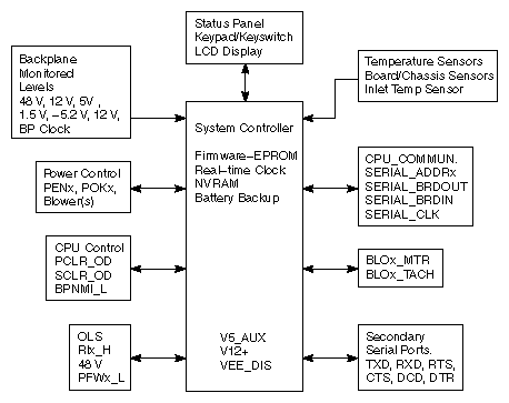
The Everest System Controller is a microprocessor with a battery-backed clock and RAM. The System Controller performs three basic functions:
The System Controller manages the system's power-on, power-off, and bootmaster arbitration processes. It also displays a running account of the status of the boot procedure and notifies the bootmaster CPU when a system event, such as power off, is initiated.
When operating conditions are within normal limits, the System Controller is a passive monitor. The only active role the System Controller plays is in monitoring the cabinet temperature and adjusting the blower speed. Its front panel LCD offers a running CPU activity graph that shows the level of each processor's activity. Previously logged errors are not available on the status panel at boot time, but are transferred into /usr/adm/SYSLOG and a new log started.
The System Controller can also act independently to shut down the system when it detects a threatening condition. Or it can adjust electro mechanical parameters (such as blower speed) to compensate for external change. The Manager position, on the key switch, provides menus used to probe for system error information.
The system serial number and event history log are stored in non-volatile RAM. The RAM, along with its battery backup and the System Controller's real-time clock, is packaged in a single, 24-pin DIP IC. The IC is socketed on the Ebus power board at location K3C3.
If the Ebus power board must be replaced, the RAM IC must be removed and installed on the new Ebus board. If the IC is not swapped, the system serial number must be written onto the new IC using the PROM Monitor serial command. The SGI part number of the RAM IC is 9018383. The manufacturer's part numbers are DS12887 and BQ3287.
 | Caution: Observe proper electrostatic discharge (ESD) precautions when handling this device. |
This chapter describes the operation of the System Controller during the power on, power off, and boot sequences, as well as during both normal system operation and during an emergency shutdown. Explanations of the possible error messages are presented in Section 4.3, "Error Messages."
Figure 4-1 illustrates the system components monitored and controlled by the System Controller.
This section provides a step-by-step description of the System Controller operation.
The OVERTEMP_L line is located on the midplane. When the sensor detects a temperature of 70°C, this DOT-OR line is pulled low to inform the System Controller of the fault. The System Controller then records the fault in the history fail, deasserts PENx, and asserts RI_H to remove all power from the system. Note that the key switch position must be changed to restart the system.
A linear temperature sensor is mounted near the analog-to-digital convertor. The tachometer output of the system's blower(s) is monitored by the System Controller. The tachometer output is used by the System Controller to control the blower speed.
An inlet temperature greater than 50°C generates an "Ambient Over Temp" message on the status panel. Low blower speed results in a "Blower RPM Failure" message. If a blower is stopped, a "Blower Failure" message is displayed. All three conditions result in a system shutdown.
The System Controller plays an active role in the power-on, boot, and reset processes. The power-on process begins when the System Controller enables the OLS outputs, supplying 48 volts to the midplane. Next, the blower(s) are turned on and their speed monitored. Then the System Controller sequentially turns on a series of power-enable lines (PENA through PENE). As each system component is brought up, the System Controller tests for a valid power-OK signal (POKA through POKE), which indicates that the voltages just enabled are within the specified range. If the power-OK signal remains high, the System Controller asserts the next power-enable line in the series. If a power-OK signal is bad (goes low), the System Controller will halt the power-on sequence. When the power-on sequence is complete, the System Controller deasserts power-clear (PCLR) and system clear (SCLR). See Chapter 3, "Power Subsystem" for additional information.
The PCLR/SCLR signals cause all of the system's processors to reset, beginning the first step in the bootmaster arbitration process (see Chapter 5, "PROM Monitor"). The System Controller then polls each of the CPU boards over the Polled Serial bus. The first CPU polled is the board with the lowest address. If that CPU has successfully passed its self-test, it notifies the System Controller that it is becoming the bootmaster, and sends interrupts to any other CPUs. If the first CPU failed its self-test, the System Controller will increment the CPU address by one and offer the bootmaster role to the next CPU. The first CPU board to successfully complete its self-test and respond to the poll becomes the bootmaster. The bootmaster CPU takes control of the boot process and uses the serial link to the System Controller to transmit status and error messages.
When the operator requests a reset using the status panel, the System Controller asserts the SCLR line, as it does following the power-on sequence. The processors are reset and the boot arbitration and power-on test process starts over. However, the 48 VDC is never removed from the midplane.
 | Note: Before requesting a system reset, terminate all processes and run an init 0 to halt IRIX gracefully. |
During normal system operation, the System Controller periodically monitors the system backplane voltages, the backplane clock, the air temperature in the cabinet, and the blower speed. The Power Fault Warning (PFW) signals, from the offline switchers, are also monitored in order to allow the system to gracefully power-off in the event of an impending loss of power. Status messages from the bootmaster CPU are transmitted to the System Controller and are available at the controller's display.
The System Controller will issue and display a warning if an abnormal condition is detected but does not warrant a system shutdown. This condition can be detected by either the System Controller's sensors or by the bootmaster CPU. In these cases, the warning is issued only to inform the user.
If a condition is detected that calls for a system shutdown, the System Controller issues an alarm. If the situation is not immediately dangerous, the System Controller will wait until it receives a "Set System Off" message or until its internal timer counts down. This delay in the shutdown sequence is designed to give UNIX ample time to perform an orderly software shutdown and to sync the system disks before power is removed.
If the reason for the shutdown requires immediate action, such as an out-of-spec voltage or a voltage failure POK condition, the System Controller will log a message and shut down immediately. In these cases, the power subsystem is shut down gracefully, but the system does not have time to sync disks or to halt UNIX.
Following the alarm, the System Controller disables power to the system boards and peripherals using the PENx_low signal without turning off the 48 volts from the OLSs. The System Controller displays a fault message and the fault LED next to the status panel lights.
| Note: First, check the status panel's event history display for error messages. Then, inspect the corresponding Fault LEDs to localize the problem. The appropriate fault LEDs will remain lit after the system has shut down. Turning off the system power (using either the key switch or the circuit breaker) or rebooting will reset the fault LEDs only if the fault has been corrected. |
Restore power by turning the key switch Off for 30 seconds, and then On (turning the key switch Off clears any fault LEDs that are lit). The System Controller will begin the start-up sequence. If the fault still exists, the system will shut down again and repeat the previous fault message.
| Caution: Overvoltage faults are potentially damaging to the system components. Refer to the "Error Message" section for more information. |
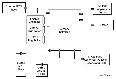
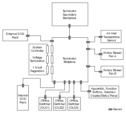
The System Controller monitors temperature sensors on the CPU (IP19 and IP21), MC3, IO4, and 512S (rackmount systems only). Additionally, there is an inlet temperature sensor located in the upper right corner of the cardcage in the deskside systems, and in either CC3 or on the jumper board in the rackmount systems.
If the System Controller shuts the system down because the temperature sensors on one or more of the boards is too high, power is removed from all system components, including the System Controller itself. To determine the origin of the fault, cycle the key switch off and then on and check the displayed error message. If the system immediately shuts down again, wait for several minutes to allow the mechanical temperature sensor switch to cool below its trip point.
There are six categories of error messages displayed by the System Controller:
bootmaster arbitration problems at power-on or reset
bootmaster CPU messages (described in Chapter 5, "PROM Monitor")
system events – immediate power-off
system events – delayed power-off
system events – informative, System Controller internal problems
Table 4-1 through Table 4-5 describe five of the six categories of error messages listed above.
Table 4-1. Bootmaster Arbitration Problems at Power-On or Reset
Master CPU Selection Message | Context and Meaning of Message |
|---|---|
BOOT ARBITRATION HAS NOT STARTED | This message is briefly displayed at power-on and at reset. It disappears unless the System Controller debug switch, bit 6, is set (preventing arbitration). |
BOOT ARBITRATION IN PROGRESS | The System Controller is scanning all slots and CPUs, looking for a response on the Serial Bus. The bootmaster CPU is expected to respond. |
ARBITRATION COMPLETE SLOT OXZZ | The System Controller finds a responding CPU. It continues to listen only to this CPU on the Serial Bus. |
ARBITRATION ABORTED | The System Controller stops looking for the bootmaster CPU. This happens if any status panel key is pressed during arbitration. To restart the arbitration process, use the "SCLR" menu to issue a backplane reset. |
BOOT IS INCOMPLETE FAULT IS NO MASTER | The System Controller completes ten scans of all slots and finds no responding CPU on the Serial Bus. Either no CPU is running or the System Controller is faulty. If the System Controller has failed, the system will boot normally, but the CPU histogram will not be displayed and the IRIX SYSLOG will show no system serial number found. |
Table 4-2. System Events – Immediate Power-Off
Error Message | Failure Area/Possible Solution |
|---|---|
POKA FAIL | The System Controller detects a power supply fault and initiates the power-off sequence (except 48 V). |
POKB FAIL | Same as above. |
POKC FAIL | Same as above. |
POKD FAIL | Same as above. |
POKE FAIL | The System Controller detects a power supply fault. The condition is logged but no power-off sequence is initiated. |
BRD/CHASSIS OVR TEMP | The System Controller detects an overtemperature condition and initiates a power-off sequence. |
POWER FAIL WARNING | The System Controller detects an AC power failure. |
NO SYSTEM CLOCK | The System Controller could not detect a system clock on the midplane, and initiates a power-off sequence. |
1.5 V OVER VOLTAGE | The System Controller detects a power supply fault and initiates a power-off sequence. The System Controller does not turn power on until the operator selects "MENU - System Log." This process guards against overvoltage damage by forcing the operator to examine the System Event Log. |
5 VDC OVER VOLTAGE | Same as above. |
12 VDC OVER VOLTAGE | Same as above. |
-5.2 VDC OVER VOLTAGE | Same as above. |
-12 VDC OVER VOLTAGE | Same as above. |
48 VDC OVER VOLTAGE | Same as above. |
1.5 VDC UNDER VOLTAGE | The System Controller detects a power supply fault and initiates the power-off sequence. |
12 VDC UNDER VOLTAGE | Same as above. |
-5.2 VDC UNDER VOLTAGE | Same as above. |
-12 VDC UNDER VOLTAGE | Same as above. |
48 VDC UNDER VOLTAGE | Same as above. |
1.5 VDC HIGH WARNING | The System Controller detects a voltage out-of-range. The condition is logged but no power-off sequence is initiated. |
1.5 VDC LOW WARNING | Same as above. |
5 VDC HIGH WARNING | Same as above. |
5 VDC LOW WARNING | Same as above. |
12 VDC HIGH WARNING | Same as above. |
12 VDC LOW WARNING | Same as above. |
-5.2 VDC HIGH WARNING | Same as above. |
-5.2 VDC LOW WARNING | Same as above. |
-12 VDC HIGH WARNING | Same as above. |
-12 VDC LOW WARNING | Same as above. |
48 VDC HIGH WARNING | Same as above. |
48 VDC LOW WARNING | Same as above. |
POWER CYCLE | The System Controller receives a command to perform a power-off, followed by a power-on, from the System Controller serial port. |
Table 4-3. System Events – Delayed Power-Off
Error Message | Failure Area/Possible Solution |
|---|---|
AMBIENT OVER TEMP | The System Controller detects an overtemperature condition. An alarm is sent to the CPU and five seconds later the System Controller initiates the power-off sequence. |
BLOWER A FAILURE | The System Controller detects a fan problem. An alarm is sent to the CPU and five seconds later the System Controller initiates the power-off sequence (rackmount systems only). |
BLOWER B FAILURE | Same as above (rackmount systems only). |
BLOWER FAILURE | Same as above (deskside systems only). |
BLOWER A RPM FAIL | The System Controller detects a fan not at speed. An alarm is sent to the CPU and five seconds later the System Controller initiates the power-off sequence (rackmount systems only). |
BLOWER B RPM FAIL | Same as above (rackmount systems only). |
BLOWER RPM FAILURE | Same as above (deskside systems only). |
TEMP SENSOR FAILURE | The System Controller detects a temperature sensor with a reading so far out of range that the sensor is assumed to have failed. The condition is logged but no power-off sequence is initiated. |
FP BUTTON STUCK | The System Controller detects a status panel button stuck in the depressed position. After a 30-second wait, the power-off sequence is initiated (the depressed button interferes with the System Controller's normal monitoring operation). |
The area and possible solution for each error message in the previous table is general by default. To obtain more specific information, you can follow three possible paths:
Swap out the suspected faulty FRU and power on the system again.
Plug your laptop into the system console port (Port 1) and probe for more specific fault information. Note that if the fault lies in the IO4 or IO4 pathway, you may be unable to access the system console port
Plug your laptop into the System Controller port, labeled External Controller Serial, using the cable permanently attached to the port. On rack-mounted systems, this port is located in the lower left corner of the midplane (when facing the front of the chassis). Deskside systems have the port located in the lower right corner of the backplane (when facing the rear of the chassis).
Table 4-4. System Events – Informative
Error Message
Error Meaning
SYSTEM ON
The System Controller reports the
power-on sequence completed.SYSTEM OFF
The System Controller reports the
power-off sequence completed.SYSTEM RESET
The System Controller generates a backplane reset, due to menu selection or serial port request.
NMI
The System Controller generates a backplane NMI, due to menu selection.
SCLR DETECTED
The System Controller detects a backplane reset, then initiates the bootmaster arbitration process.
BOOT ERROR
System Controller bootmaster arbitration could not find any host CPU responding on the serial bus. The System Controller is not able to communication with the host CPU. The host CPU may not be running or may continue to boot normally.
INVALID CPU COMMAND
The System Controller detects bad command syntax from the host CPU on the Serial Bus. The command is ignored.
Table 4-5. System Controller Internal Problems
Error Message
Error Meaning
BAD MSG: CPU PROCESS
The CPU or System Controller process has received an invalid message.
BAD MSG: DISPLAY
The display process has received an invalid message.
BAD MSG: POK CHK
The power OK check process received an invalid message.
BAD MSG: SEQUENCER
The sequencer process has received an invalid message.
BAD MSG: SYS MON
The system monitor process has received an invalid message.
COP FAILURE
The Computer Operating Properly (COP) timer has exceeded time limits. The System Controller firmware must write to a COP timer port before it times out. If the firmware exceeds the time allowed between writes to a COP port, an interrupt is generated. The System Controller firmware may have entered an endless loop.
COP MONITOR FAILURE
A Computer Operating Properly (COP) clock monitor failure was detected. The System Controller clock oscillator is operating at less than 10 kHz.
FP CONTROLLER FAULT
An error was detected in the front panel LCD display control process.
ILLEGAL OPCODE TRAP
The System Controller's microprocessor tried to execute an illegal instruction, probably because of a stack overrun followed by a process switch.
MEMORY FAILURE
The System Controller's internal memory experienced a failure.
PULSE ACCU INPUT
An interrupt was detected on the pulse accumulator input port. The port is not used and an interrupt is considered an error.
PULSE ACCU OVERFLOW
The pulse accumulator overflow port received an interrupt. This port is unused and the interrupt is considered an error.
SOFTWARE INTERRUPT
A software generated interrupt was detected. This function is not supported and the interrupt is considered an error.
SPI TRANSFER
An interrupt was detected on the synchronous serial peripheral interface. This interface is not supported and the interrupt is an error.
STACK FAULT PID 0–6
One of the seven stack areas used by a System Controller process has overflowed its assigned boundaries
TIMER IN COMP 1
The timer input compare port received an interrupt. The port is not used and the interrupt is considered an error.
TIMER IN COMP 2
TIMER IN COMP 3
TIMER OUT COMP 1–5
One of the five timer output compare ports received an interrupt. The port is not supported and the interrupt is considered an error.
TIMER OVERFLOW
A timer overflow port interrupt occurred. This port is not used and the interrupt is considered an error.
SCI SERIAL COMM
REAL TIME INTERRUPT
INTERRUPT REQUEST
EXTEND INT REQUEST
CPU NOT RESPONDING
BAD WARNING/ALARM
BAD ALARM TYPE
BAD WARNING TYPE
FP READ FAULT
| Note: Internal errors will cause an error message to be displayed, but will not shut down the system. |
The locations of the System Controller sensors for both the deskside and rack-mounted systems are shown in Figure 4-3 and Figure 4-4, respectively.
This section provides a sequential listing of the available System Controller menus, as well as descriptions of the menu functions.
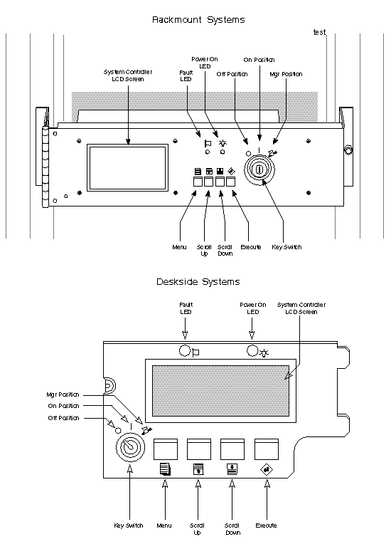
The menus are accessed and their functions executed using four function buttons. Press the Scroll Up and Scroll Down buttons to locate a specific menu. Press the Menu button to view the selected menu. Press the Execute button to perform the menu function. See Figure 4-5 for an illustration of the System Controller display and function buttons.
There are four menus that are accessible when the key switch is in the On position. Figure 4-5 describes these menus.
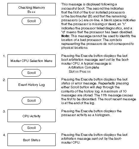
Continuing to pressing the Scroll buttons will loop through the four menus. When the function buttons are not used, the display defaults to the CPU activity histogram.
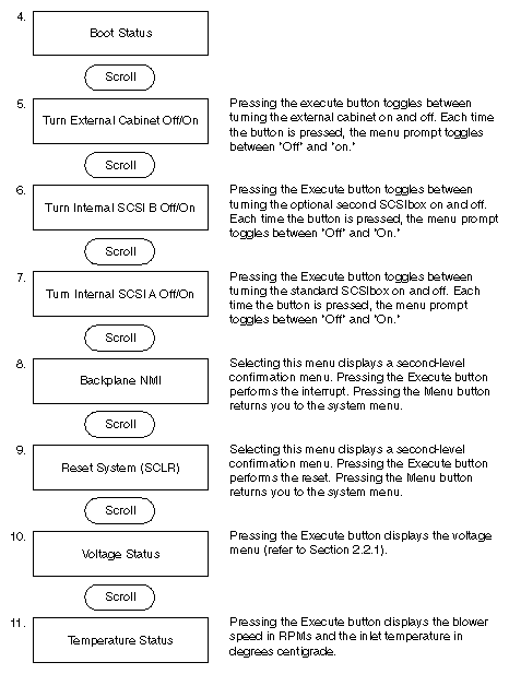
In addition to the four menus just described, the Manager position provides access to eight more menus. Figure 4-6 describes these menus.
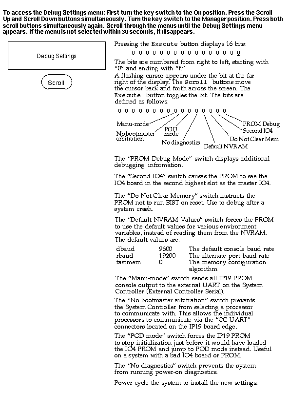
The Debug Menu allows you to set several switches that enable or disable various diagnostic features of the system. These features include:
entering PROM debug mode
enabling a second IO4
choosing whether or not to clear memory on system reset
resetting the non-volatile RAM (NVRAM) configuration
choosing whether or not to run system power-on diagnostics
entering power-on diagnostics (POD) mode
choosing whether or not the System Controller selects the bootmaster CPU
setting "manual mode," where all CPU (IP19 and IP21) PROM console output is sent to the external UART (serial port) on the System Controller
Figure 4-7 describes how to enter the Debug Menu and set the various switches.