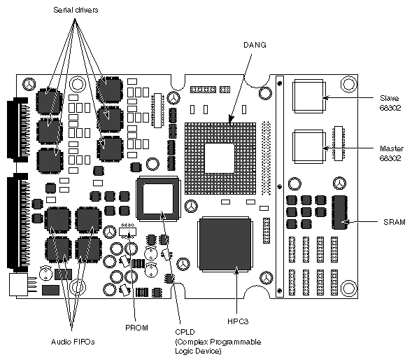
This chapter highlights the features of the Audio/Serial Option (ASO) board upgrade and provides a block diagram description and a board-layout drawing.
The ASO supports the following serial features:
six asynchronous serial ports with 9-pin D-shell connectors that are software-selectable between RS-232 and RS-422
no loss of serial characters at 115.2 Kbaud/sec
at least 115.2 per channel while running in full duplex mode
baud rates up to 38.4 through the standard tty interface or up to 115.2 through a user-supplied program

Caution: The baud rate can be set to a higher speed (beyond 115.2 Kbaud/sec), however, these rates are not supported by Silicon Graphics. Operating beyond 115.2 can result in possible loss of serial characters and overall degraded performance.
The ASO provides the following audio input and outputs.
headphone output (stereo)
microphone input (mono or stereo)
line-level input (stereo)
line-level output (stereo)
digital input/output
See Chapter 3, "Configuring the Ports," for a list and description of the audio ports.
 | Note: The ASO does not provide audio time stamping. |
The ASO board provides audio I/O and asynchronous serial I/O and handles real-time streams of data. The ASO also channels 5 volts of power for the audio components. The
5 volts is supplied through the IO4 board.
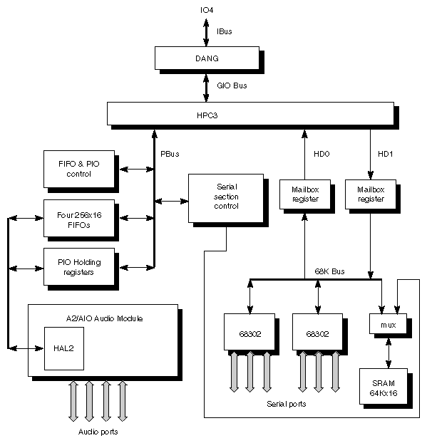
Figure 1-1 provides a block diagram of the ASO board. A DANG (Dual-purpose Adapter for Network and Graphics) chip translates between the IBus and GIO bus. The 64-bit Ibus is the main internal bus on the IO4 board. The GIO (graphics input/output) bus is the major bus on the ASO board. Data transfers to and from the board are done through DMAs, either through the audio or serial section. An HPC3 (High-Performance serial Controller) provides buffering and additional DMA control.
Two Motorola® MC68302™ integrated multiprotocol processors provide three serial controllers each. One serves as the slave, the other as the master. Both master and slave contain independent DMA engines for moving incoming and outgoing serial data.
The master 68302 processor executes code from an external 128 KB SRAM. The master 68302 also performs the necessary housekeeping functions on data sent to and received from the host.
Two word-wide mailbox registers interface the 68K bus to the HD0 and HD1 ports of the HPC3 chip. The FIFO of the HD ports allow enough serial data to be exchanged with host memory during serial data transmission to overcome any system latency.
The audio section of the ASO board uses the same basic design as the audio circuitry in the Indigo2™ system. The major component in the audio section is a HAL2 ASIC. The HAL2 provides the data path and control logic to interface the HPC3 Pbus and the audio devices on the module.
The audio FIFOs (four 256 x 16) respond to DMA channel requests from the HAL2 and transmit or receive DMA information as directed by the HAL2. The HAL2 also allows a PIO to interleave whenever a DMA channel request has been completed. The HPC3 side of the audio FIFOs makes sure that the HAL2 side never overruns the audio FIFOs.