This chapter describes how to install the Audio/Serial Option (ASO) board into a Challenge, Onyx, POWER Challenge, POWER Onyx, or Reality Station system. The ASO is a short mezzanine board that installs on any available IO4 board. A system can support a maximum of one ASO board at first-product release.
 | Note: The addition of an ASO board does not affect the operation and performance of existing serial ports on the system. |
Be sure to read the following information before you begin installation.
 | Warning: Installation of these upgrades requires specific training and technical knowledge. These instructions are provided for use by Silicon Graphics system support engineers (SSEs) or other Silicon Graphics-trained personnel only. This equipment utilizes electrical power internally that is hazardous if the equipment is improperly disassembled. |
 | Caution: This equipment is extremely sensitive and susceptible to damage caused by electrostatic discharge (ESD). ESD is an electrical discharge caused by the build-up of electrostatic potential on clothing and other materials. |
Follow these ESD-preventive measures:
Connect a ground strap to your wrist when installing and removing peripherals.
Be sure that you and all of the electrical equipment that you handle during this installation remain at a ground potential of zero to avoid damage from ESD.
Remove a board from its antistatic bag only when you are properly grounded with a ground strap, and only when you are working on the board or installing it.
Do not use an ohmmeter on a board.
The system must be running one of two operating system versions.
5.3 or later for IP19-based Challenge, Onyx, and Reality Station systems
6.0.1 or later for IP21-based POWER Challenge and POWER Onyx systems
the system must also have the ASO software driver on CD-ROM
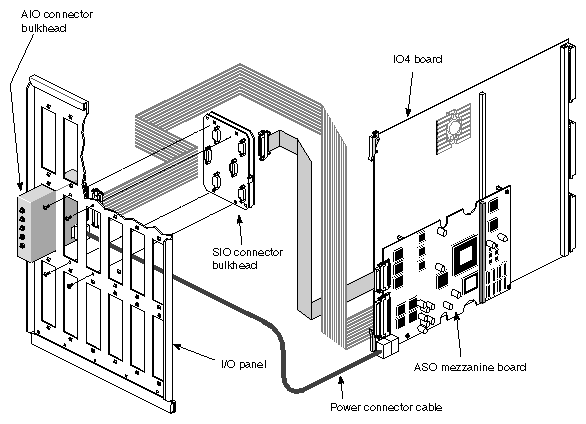
Verify that the ASO package is complete. It should contain the items listed in Table 2-1 (see also Figure 2-1).
Description | Part Number |
|---|---|
Audio Serial Option board | 030-0753-001 |
SIO connector bulkhead | 013-1203-001 |
AIO connector bulkhead | 013-1204-001 |
SIO cable assembly | 018-0495-001 |
AIO power harness assembly | 015-0239-001 |
AIO cable assembly | 018-0496-001 |
| Caution: If anything is missing, do not proceed with the installation. Contact the customer or the customer's salesperson. |
This section describes the steps for installing the ASO into a Challenge, Onyx, POWER Challenge, and POWER Onyx deskside or rackmount system, or the Reality Station deskside system. Figure 2-1 provides an overview of the hardware installation.
| Caution: This equipment is extremely sensitive and susceptible to damage by electrostatic discharge (ESD) a spark caused by the buildup of electrical static. You must use proper ESD preventive measures as explained in Section 2.1, "Safety Information." |
Verify that the IRIX operating system is the correct version for this upgrade, using the command below. Do not proceed until the correct version of IRIX is installed. See Section 2.2, "Software Dependencies."
% versions eoe1
I  eoe1  date  Execution Only Environment 1, version
Verify that the customer has backed up the filesystem.
Invoke the shutdown command and wait for a power off indication.
Shut down the system by turning the key on the System Controller panel (located at the front) to OFF. Wait a minute for the system to shut down, then switch the circuit breaker to OFF.
Warning: Failure to turn off the circuit breaker may result in electrical shock. Failure to wait for the system to shut down may cause irreparable damage to system components or data. Open the front door (on a deskside system) or rear door (on a rackmount system) and pull down the I/O panel on the chassis to expose the IO4 boards.
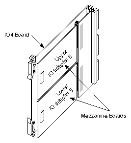
Locate the IO4 boards that are currently installed. Table 2-2 shows the possible locations of the IO4 board in each system. In addition, follow these guidelines for selecting a mezzanine slot.
If the system has only one IO4 board, this is the location for the mezzanine board. The ASO, which is a short mezzanine board may be installed in either the upper or lower position on the IO4 board, as illustrated in Figure 2-2.
If there are no unoccupied mezzanine slots, you must install another IO4 board. Contact the sales representative to order one. The installation cannot be continued until a mezzanine slot is available.
Remember: only one ASO board is supported in the first product release.
Table 2-2. Available IO4 Slots in Each System
System
Slots That Can Be Used
Challenge or POWER Challenge L (Deskside) Server
Upper or lower mezzanine slot on an IO4 board in slot 5, 4, or 3
Onyx, POWER Onyx, or
Reality Station (Deskside) WorkstationUpper or lower mezzanine slot on IO4 board in slot 3
Challenge or POWER Challenge XL (Rackmount) Server
Upper or lower mezzanine slot on an IO4 board in slot 15, 13, 11, 9, 7, or 5
Onyx or POWER Onyx (Rackmount) Workstation
Upper or lower mezzanine slot on an IO4 board in slot 11, 9, 7, or 5
Follow the steps below to install the ASO board.
Remove the IO4 board that you have selected from the chassis.
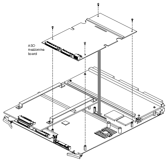
Lay the board on a flat antistatic surface so that the component side faces up and the SCSI connectors face toward you, as illustrated in Figure 2-3.
Locate the selected mezzanine slot (upper or lower) and remove the four screws from the standoffs, as illustrated in Figure 2-3.
Position the ASO board onto the mezzanine board receptacle on the IO4 board and make sure the standoffs match the board's holes. Figure 2-3 illustrates the correct positioning for the lower mezzanine slot.
Replace the standoff screws. Use the screws removed previously or the shipped screws. The standoffs have a "float" feature, so the ASO can move slightly when the screws are fully tightened.
Reinstall the IO4 board into the chassis. Push the board firmly into the backplane. If the board has a VCAM board, the VCAM board must also connect to the backplane.
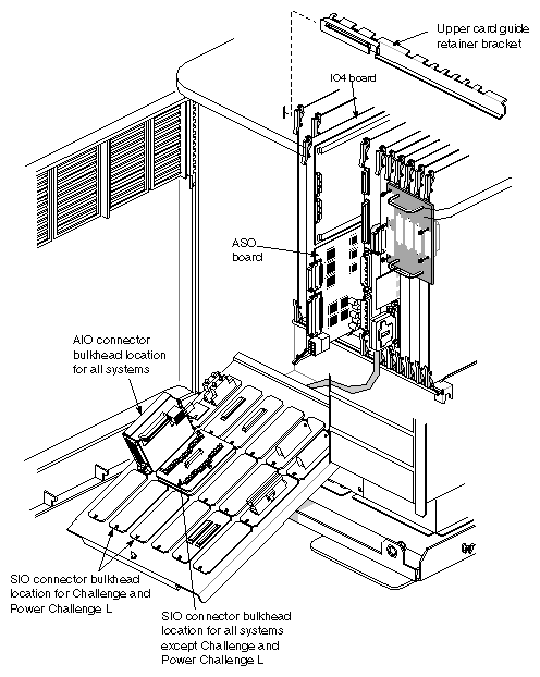
The ASO has two I/O connector bulkheads that occupy three I/O panels (see Figure 2-1 and Figure 2-6):
the AIO (audio) connectors use one I/O panel slot
the SIO (serial) connectors use two I/O panel slots
Caution: The AIO connector bulkhead must be installed in the leftmost slot in the middle row on the I/O panel so that the I/O panel can properly close and to allow sufficient room for excess ASO cabling (see Figure 2-6).
Follow these instructions to install the I/O connector bulkheads.
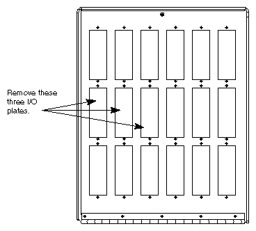
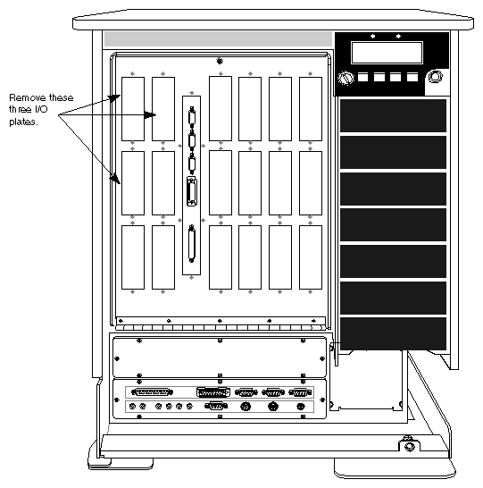
If you have an Onyx, POWER Onyx, or Reality Station deskside, or any of the rackmount systems, remove the three left I/O plates from the middle row of the I/O panel (see Figure 2-4). If there are existing connector panels in these slots, move these connectors to another location on the I/O panel.
Figure 2-4. I/O Plate Removal Locations for Onyx and POWER Onyx Deskside, Reality Station, and All Rackmount Systems
If you have a Challenge or POWER Challenge L (deskside) system, remove the two left plates on the upper row and the leftmost I/O plate on the middle row (see Figure 2-5). If there are existing connector panels in these slots, move these connectors to another location on the I/O door.
Install the AIO connector bulkhead into the leftmost I/O slot position in the middle row of the I/O panel (see Figure 2-6).
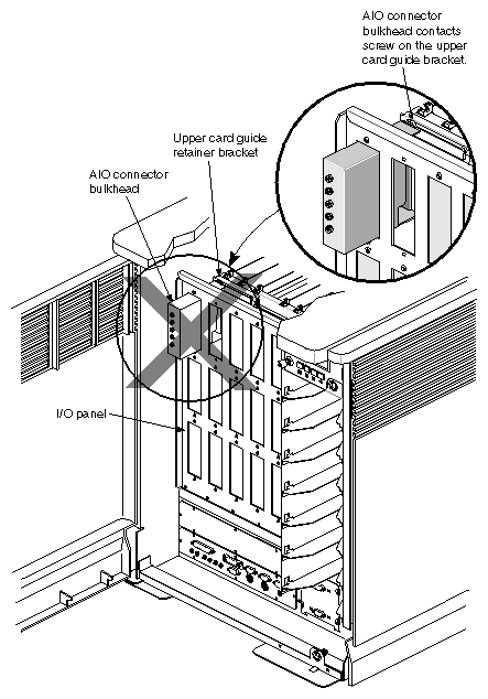
Caution: You must install the AIO (audio) connector bulkhead as shown in Figure 2-6. This positioning normally provides the most room for cabling and also does not interfere with existing IO4 SCSI cables. If you place the audio bulkhead in any other slot position, you could damage existing cables and board connectors when the I/O panel is closed.
In addition, do not install the audio bulkhead into the upper left slot on the I/O panel. Assuming that an upper card guide retainer bracket is in place, this causes the bulkhead to the hit against a screw on the upper card guide bracket when you try to close the I/O panel (see Figure 2-7). This prevents the I/O panel from properly closing.
Caution: Do not place the AIO connector bulkhead in the upper left slot position. If you have an Onyx or POWER Onyx deskside system, Reality Station, or one of rackmount systems, install the SIO connector bulkhead into the second and third I/O slots of the middle row of the I/O panel. See Figure 2-6.
If you have a Challenge or POWER Challenge L system, install the SIO connector bulkhead into the upper left slots on the first row of the I/O panel. See Figure 2-6.
Note: This positioning normally provides the most room for cabling and also does not interfere with existing IO4 SCSI cables.
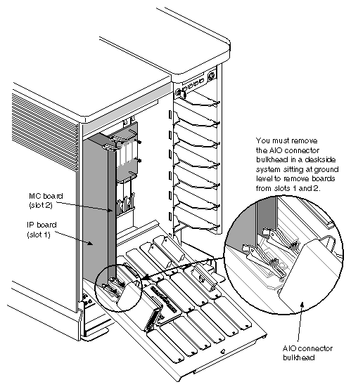
If you have a deskside system that sits at ground level, you must remove the AIO connector bulkhead whenever you need to remove an MC3 or IP19/IP21 board that is located in the first two left-hand slots (see Figure 2-8). Otherwise, the height of the AIO connector bulkhead prevents the boards from being removed from the cardcage.
There are three internal ASO cable assemblies (see Figure 2-9):
AIO power harness (p/n 015-0239-001)
100-pin AIO cable assembly (p/n 018-0496-001)
60-pin SIO cable assembly (p/n 018-0495-001)
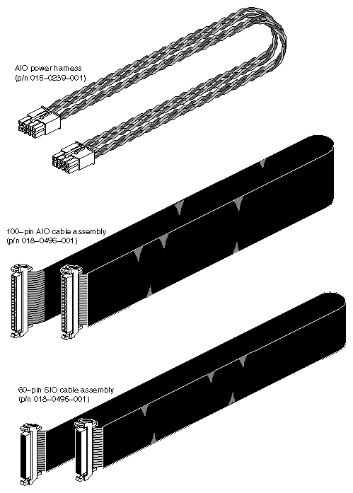
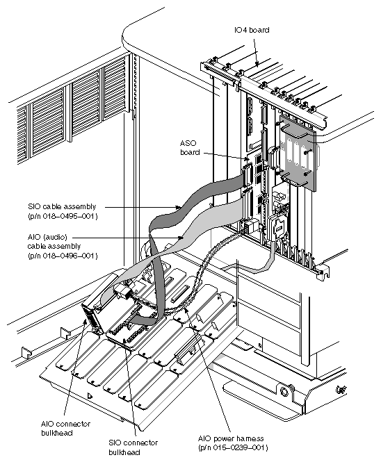
Follow the steps below and see Figure 2-1 and Figure 2-10 to attach the internal ASO cables to the ASO board and to the audio and serial connector bulkheads on the I/O panel.
Locate the 100-pin AIO cable assembly (p/n 015-0239-001)) and the AIO power harness (p/n 015-0239-001). See Figure 2-9.
Attach the AIO cable assembly and power harness to the corresponding ASO board connectors and I/O panel connector bulkhead, as shown in Figure 2-1 and Figure 2-10.
Locate the 60-pin SIO cable assembly (p/n 018-0495-001). See Figure 2-9.
Attach the SIO cable assembly to the corresponding ASO board connector and I/O panel connector bulkhead, as shown in Figure 2-1 and Figure 2-10.
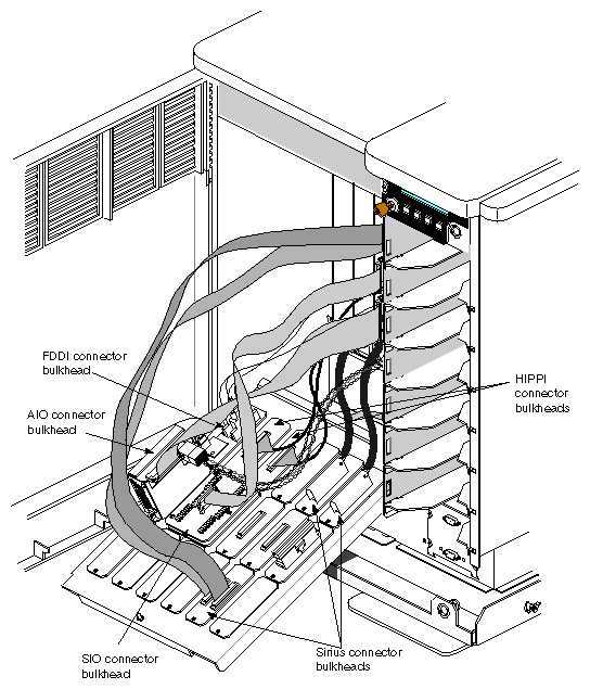
After you have attached the ASO cables, you may have a morass of cables. A typical cabling scenario is shown in Figure 2-11. Carefully tuck excess cabling into the sides of the system so that the cables do not prevent you from closing the I/O door.
Note: The ASO cable lengths were determined after conducting worst-case cabling tests in a rackmount system. Afterwards, carefully close the I/O panel and make sure that the cables are not pushing excessively against any board connectors and causing possible damage.
The ASO software installs through inst from a CD-ROM. There are three pieces of software that need to be installed:
aso.sw.ser
aso.man.ser
patch 395 for an IRIX 5.3 system or patch 397 for an IRIX 6.0.1 system
Follow these steps to install the ASO software.
After installing the ASO hardware, flip the circuit breaker to ON, wait for one minute, then turn the key switch on the front to ON.
Boot and log into the system as superuser.
If required, mount the CD-ROM drive as shown in the following example:
# mount -r /dev/dsk/dks0dns7/CDROM
where n is the address of the CD-ROM reader.
Install the first of three ASO subsystems using inst:
# inst -f /CDROM/dist/aso.sw.ser
You should then see a display similar to the following:
Default location of new software is xxxxxx

If you are a first-time inst user, give the command "help beginner".

Inst Main Menu
 1. from [source]                 Specify location of software to be installed
 2. list [keywords] [names]       Display information about software subsystems
 3. go                            Perform software installation and removal now
 4. install [keywords] [names]    Select subsystems to be installed
 5. remove [keywords] [names]     Select subsystems to be removed
 6. keep [keywords] [names]       Do not install or remove these subsystems
 7. step [keywords] [names]       Enter interactive mode for install/remove/keep
 8. versions [args]               Get information about installed software
 9. help [topic]                  Get help in general or on a specific word
10. admin                         Go to the Administrative Commands Menu
11. quit                          Terminate software installation
At the inst main menu, type list to verify the software:
Inst> list
After verifying that the correct software is called out, type go to begin installation.
Inst> go
When the installation is complete, install the second of three subsystems:
Inst> install aso.man.ser
Afterwards, repeat steps 6 and 7 to complete the installation of the second subsystem.
When done, install the third subsystem: patch 395 for an IRIX 5.3 system or patch 397 for an IRIX 6.0.1 system.
Inst> install patchSGxxxxx
where xxxxx is the patch number you wish to install.
Caution: You must specify the required patch number, since you cannot install all the patches at one time. For example, if you give the command install default, you see the error desktop_tools.sw.tools requires desktop_eoe.sw.fam 1019999999. Afterwards, repeat steps 6 and 7 to complete the installation of the final subsystem.
Once the patch is installed, enter quit to exit from inst.
To reconfigure the kernel, type the following command (as superuser):
# autoconfig
Reboot the system, when you are done.
If you have an IP21 system, you will not be able to use the audio capabilities until you run the MAKEDEV command as follows:
At the IRIX prompt, type cd /dev.
Afterwards, become superuser.
Type ./MAKEDEV. This command adds/updates the required files to the /dev/hdsp directory such as hdsp0master.
Note: The MAKEDEV command takes about 10 minutes to execute. From the /dev/hdsp directory, type ls -l to check if the files are present. Also note if the time and date of the files have been updated.
To verify installation, type hinv at an IRIX shell and check that the ASO hardware is listed.
You should see a display similar to the following:
..... ASO 6-port Serial board [b]: revision [d].[e]. [c], Ebus slot [s], IO Adapter [a] Iris Audio Processor: version A2 revision x.x.x ..... |
where:
[b] is the board number. It will automatically be 0 at first product release.
[d] is the DANG revision (see Figure 1-2), for example revision B or C.
[e] is the external CPLD revision (see Figure 1-2).
[c] is the internal (Silicon Graphics) CPLD revision (see Figure 1-2).
[s] is the Ebus slot number for example, 3 (typically) for a deskside system.
[a] is the IO adapter number, for example, 5 or 6 (see Figure 2-2).
| Note: If the board is not listed, reinstall the product (the board and all cables) making sure everything is firmly seated and tightly connected. |
To test some of the audio and serial ports of the ASO, you need:
a headphone and a microphone (if available) for the audio tests
an ASCII terminal for the serial test
Follow these instructions to test the ASO audio ports.
If it is available on the system, bring up the Audio Panel from the Desktop toolchest or type apanel from a shell.
Plug a headphone into the headphone port of the AIO connector bulkhead.
Go to a directory that contains sounds such as /usr/lib/sounds/prosonus/instr.
Type playaiff <sound filename> and listen for the sound. Check the volume control by adjusting the volume through the Audio Panel (if available).
To test the microphone input, select the audio confidence tests under the Run Confidence Tests in the System toolchest.
Plug the microphone and headphone into the appropriate ports on the bulkhead.
Double-click the audio test to check out the microphone port.
Follow these instructions to test the ASO serial ports.
Connect an ASCII terminal to a serial port on the ASO serial connector bulkhead. Ensure that the terminal is set for: 9600 baud (full duplex), XON/XOFF handshaking, 8 bits, and 1 stop bit.
On the ASCII terminal, press <return> and <break> until the terminal responds. Afterwards, login and then logout. Follow steps 1 and 2 to check out the other serial ports.