This chapter consists of the following topics:
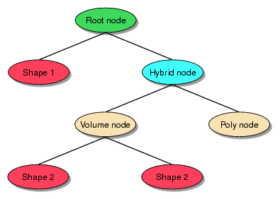
OpenGL Volumizer is an API designed to handle the volume rendering aspect of an application. You can use other toolkits, such as OpenGL Performer and Open Inventor, to structure the other elements of your application. The API allows seamless integration with other scene graph APIs because the shape node can be used as the leaf nodes of such scene graphs. Figure 9-1 illustrates a hypothetical scene graph that contains polygonal data mixed with volumetric data. In this case, the shape nodes are used to represent the volumetric components of the scene while the Poly node is used to represent the polygonal geometry.
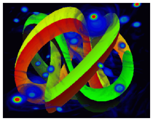
Mixing geometric objects with volume-rendered data is a useful technique for many applications. For opaque objects, the geometry is rendered first using depth buffering and then the volume data is rendered with depth testing enabled. When using APIs such as OpenGL Performer, the scene graph traversal should be done in the appropriate order to ensure correct alpha compositing. The application can ensure this by marking the volumetric nodes as transparent so that the scene traverser renders it after the opaque geometry. In the case of OpenGL Performer, this can be accomplished by creating the appropriate pfGeoState and attaching it to the volume node. Figure 9-2 shows a volumetric data set rendered along with opaque geometry using the preceding technique.
The design of OpenGL Volumizer permits integration with visualization toolkits as well. To demonstrate this aspect of that design, OpenGL Volumizer provides a new volume rendering method for the Visualization Toolkit (VTK) using 3D textures and based on the OpenGL Volumizer API. VTK is open source, free software for imaging and visualization. VTK supports a number of visualization algorithms including scalar, vector, tensor, texture, and volumetric methods. Its volume rendering method is an implementation of ray casting and 2D texture-based rendering.
In the directory VZROOT/src/, the VTK example shows how to add 3D texture-based volume rendering to VTK, encapsulated in a class that provides all the necessary steps to support 3D texture-based volume rendering. The joint implementation (OpenGL Volumizer coupled with VTK) consists primarily of an OpenGL, 3D, texture-based mapper class. This class initializes the necessary OpenGL Volumizer volume parameters (such as shape and appearance), creates the geometry, creates an appropriate shader, and manages the shape. The new class, vtkOpenGLVolumeTextureMapper3D, takes as input a vtkVolume and creates an equivalent vzShape node. Then the virtual renderer method uses TMRenderAction to draw the shape node.
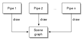
Thread safety allows applications the ability to run on large platforms for large immersive displays or to scale the graphics performance and resource use by sharing the scene graph among multiple rendering threads/processes. Typically used with OpenGL Multipipe SDK, the applications will be scalable and able to run in a Reality Center environment. Applications can scale the rendering performance of the system by compositing the intermediate results from different pipes to get the final image. Figure 9-3 shows n pipes rendering the same scene using one thread/process per pipe.
There are several topics to consider when using OpenGL Multipipe SDK with OpenGL Volumizer:
For sample code that illustrates techniques described in this section, see the volview application that ships with OpenGL Volumizer. The application is a full volume-viewer application that uses OpenGL Multipipe SDK as the underlying software layer to provide run-time configurability and scalability.
OpenGL Multipipe SDK supports the pthread and fork multiprocess mechanisms. The following table describes their use with OpenGL Volumizer:
| Mode | Prescribed Use with OpenGL Volumizer | |
| pthread | Works well with OpenGL Volumizer since OpenGL Volumizer is thread-safe. | |
| fork | Works well with OpenGL Volumizer since OpenGL Volumizer is thread-safe. Use the vzMemory class to ensure allocation of OpenGL Volumizer objects from shared memory by using the code shown in Example 9-1. Example 9-1. Using vzMemory to Allocate Objects from Shared Memory |
OpenGL Volumizer render actions manage the graphics resources on a per-pipe basis. Use the following guidelines to get proper rendering:
Ensure that OpenGL Volumizer nodes are stored as part of the shared data for the application. The data should not be replicated across multiple pipes unless there are special needs since volume data tends to be quite big in practice.
Create only one render action per MPKWindow.
Do not use multiple MPKWindows per MPKPipe since this will lead to inefficient resource management and also force unnecessary context switches. However, this practice might be acceptable for testing purposes on single-pipe machines.
Do not share the same render action among multiple MPKWindows since each window has its own GLX context and execution thread.
Rendering performance can be scaled using multiple compositing schemes. This section describes the following topics:
2D decomposition scales fill rate in a straightforward manner. If you can divide the volume data into smaller bricks, you can use view-frustum culling to scale the texture memory size also by moving these bricks in and out of the texture memory of the pipes. Section “Managing and Drawing Shapes” in Chapter 4 describes how to do this.
You can achieve even greater scalability if you use 2D decomposition in conjunction with one or both of the following techniques:
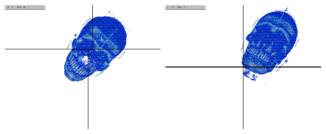
Figure 9-4 contrasts dynamic and static load balancing for a 2D compound using volview. Volume rendering is bound by fill rate; therefore, the load balancing can adjust the compound's region so that each pipe has approximately the same amount of volume to rasterize. When using static tiling, one pipe may have to render the whole volume as it is moved around. Since the slowest child dictates overall performance, the frame rate is better, in this case, when using load balancing.
DB decomposition scales fill rate and texture memory size. Divide the volume data into multiple bricks and render equal number of bricks on each of the pipes. You need to pre-modulate the transfer function (lookup table) before rendering to compensate for the image blending operation used to composite the results together.
Figure 9-5 illustrates database (DB) decomposition using OpenGL Volumizer and OpenGL Multipipe SDK. The application partitions the volume data into four separate bricks. Each of these bricks are rendered on four different pipes to generate partial images. These images are then composited and displayed on the destination channel (which is also a source in this case) to give the final image.
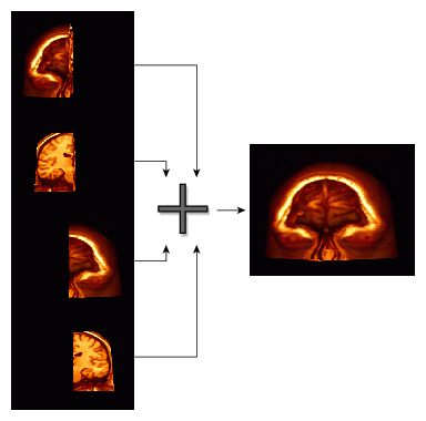
DB decomposition allows applications to linearly scale the texture memory size and fill rate performance with the number of graphics pipes on the system. For example, on a Silicon Graphics Prism system, a GPU supports over 200 Mbytes of texture memory. Using four graphics pipes in conjunction with DB decomposition provides over 800 Mbytes of texture memory.
Data streaming ( 3D decomposition) is not supported by OpenGL Volumizer since the order in which the source channels are composited cannot be controlled in this mode. However, true volume decomposition can be achieved using DB decomposition, which enables the application to scale in texture memory by distributing the data across multiple pipes.
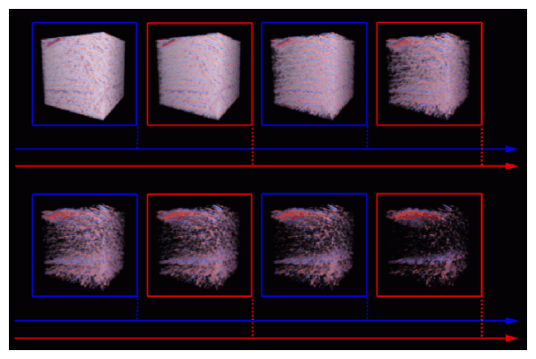
DPLEX decomposition is supported by OpenGL Volumizer. Figure 9-6 shows an example of DPLEX decomposition, where consecutive frames are rendered over different pipes. This example shows a sequence of frames as the user modifies the transfer function for this seismic data set. The even frames are rendered on pipe 1 (red) and the odd frames on pipe 2 (blue), respectively. This technique effectively doubles the frame rate with minimal application effort.