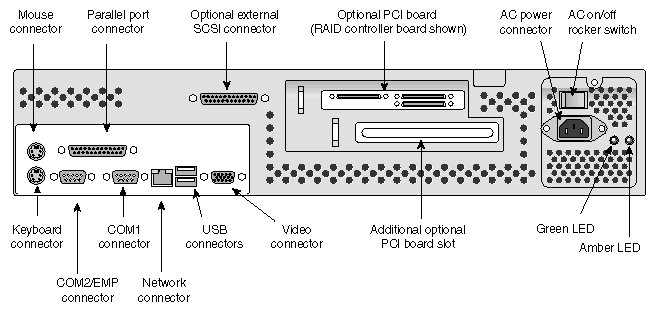
This chapter provides information about the SGI 1200 server's hardware. In the first section, information about the motherboard is presented, and in the following sections, the text and supporting illustrations provide information about chassis internals, connectors and LEDs.
The SGI 1200 server uses an Intel motherboard with the following features:
MP (Multi-Processor) ready processor host bus interface support
Dual or single Intel Pentium III processors
Support for up to 2 GB of ECC memory
Supports the ACPI (Advanced Configuration and Power Interface) power management specification
L2 cache configurations of 512 KB
Embedded dual function SCSI controller provides both Ultra2 (LVDS) wide and Ultra wide SCSI interfaces as two independent PCI bus masters
10/100 Base-T ethernet support at burst rates of up to 132 MB/sec from the PCI bus to the ethernet controller
When you first boot your system you will see an Intel mother board identification number listed (for example L440GX+). If you need specific technical information regarding your server's mother board you can access the Intel documentation directly at:
http://support.intel.com/support/motherboards/server/
The SGI 1200 server has four hard disk bays and a midplane for easy drive removal, replacement, and chassis monitoring. It supports hot-swap drives with an optional SGI 1200 server RAID controller. Two removable media drives are supported.
Figure 2-1 shows a top view of the chassis internals for an SGI 1200 server with a midplane and optional RAID controller.
In Figure 2-1, note the following:
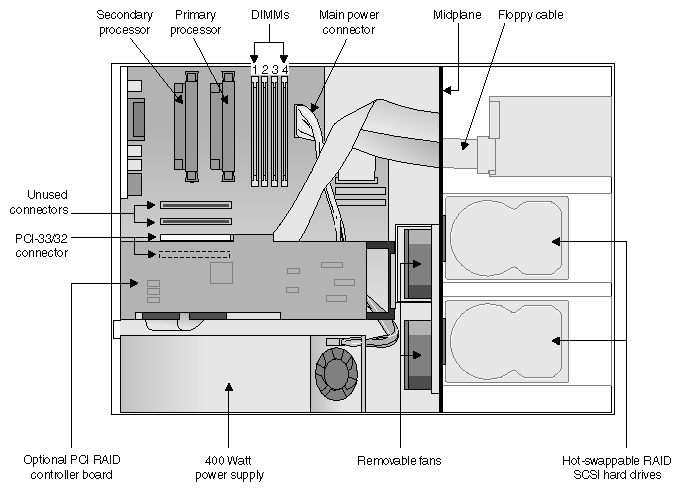
Figure 2-2 shows the midplane location and optional RAID board in the SGI 1200 server. Note that the primary cooling fans are located in the middle of the chassis.

The SGI 1200 server motherboard can be populated with up to two Intel Pentium III processors. The processors on the motherboard must be rated at the same clock speed. Contact your sales or customer support representative for information on upgrading your server's processors.
The motherboard supports from 128 MB to 2 GB of 100 MHz PC/100 SDRAM memory. The system supports only error correcting code (ECC) memory. Contact your sales or system support representative for server memory upgrades.
Figure 2-3 shows the basic cabling routes. Moving from left to right:
The floppy controller on the motherboard connects to the floppy drive.
The IDE controller on the motherboard connects to the CD-ROM drive.
The Ultra-2 SCSI controller on the optional PCI-based RAID controller connects to the midplane providing hot-swap RAID capability for four or five hard drives.
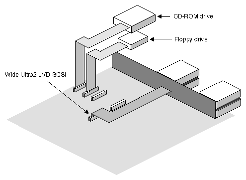
Figure 2-4 shows cabling routes without the optional PCI-based RAID controller:
Wide Ultra2 LVD SCSI capability on the motherboard connects to the midplane providing high performance disk I/O for hard drives for customers who do not require hot-swap capability with data redundancy.
External connections are not shown. All configurations support an optional Ultra SCSI connector for external SCSI devices. See Figure 2-11Figure 2-11Figure 2-11 for the location of this connector on the back panel and Table 4-1 for additional information.

The SCA midplane on the SGI 1200 server provides easy hard drive removal and replacement. Adding a RAID controller supports hot-swap capability for SCA-2 hard drives using Ultra2 SCSI technology on a single channel. All bus termination and SCSI ID selection for SCA hard drives is handled automatically by the midplane.

The SCA midplane uses Qlogic's GEM processor to implement the SAF-TE (SCSI Accessed Fault Tolerant Enclosure) specification. The processor monitors the removal and replacement of Ultra-2 SCSI SCA hard drives, scans the SCSI bus for errors, and senses chassis over-temperature and failed fan conditions.
The following SCSI error conditions are indicated as failures:
hard drive not spinning
hard drive not responding to low level SCSI commands
Figure 2-5 shows the SCSI IDs that the midplane assigns. The midplane itself uses SCSI ID 9.

Temperature sensors on the right and left side of the midplane monitor the chassis temperature. When the sensors detect internal chassis temperatures above 50 degrees C (equipment damaging conditions), the midplane issues a signal that causes the amber Global Failure LED on the front panel to light.
The chassis fans are also monitored, and a fan failure causes the Global Failure LED to light.
Figure 2-6 shows some of the main chassis components in an exploded view. They are:
Front drive cover
Hot swappable SCA hard drives
Fans
Optional PCI cards
Power supply

There are two push buttons and several LEDs on the right hand side of the SGI 1200 server front panel. The following sections provide information about the buttons and LEDs on the front and back panel, and information about error conditions that the LEDs can indicate. The information in this section can help you make a quick visual inspection of the status of the hard drives, network connections and internal components of your SGI 1200 server.
If the amber Global Failure LED that you can view through the front cover does light, you can use the information in this section, and Chapter 5 to troubleshoot the failure source.

Pressing this button powers on the SGI 1200 server. If you decide that you don't want to power up the SGI 1200 server, press the button again to immediately shut down the system. The blue LED will blink briefly and the server shuts down before the BIOS or operating system are initialized.
When the SGI 1200 server is operating, holding this button for five seconds issues a shutdown command to the system.

The reset push button connects to the motherboard. If the SGI 1200 server freezes during use, pressing the reset button issues a hardware reset to the BIOS, and the operating system reloads.
 | Caution: Pressing the reset button is the last resort for dealing with a non-responsive server. Any work not saved to disk will be lost when the reset button is pressed. Pressing the reset button can leave the operating system in an uncertain state, so try logging into an alternate console to cancel a runaway process before you reset your system. Check with your system administrator. |

When the blue LED lights, the SGI 1200 server has a live AC power connection. See also “Power Supply LEDs”.
The green LED located beneath the blue AC power LED is the disk activity LED. It flickers during disk activity.

The green Ethernet activity located above the amber Global Failure LED flickers during 100 and 10 Mbps Ethernet activity.


There are a variety of failure conditions that cause the amber Global Failure LED to light, including:
AC power into the power supply out of normal range
DC power outputs from the power supply not within specified range
A variety of hard disk drive failure conditions (see the troubleshooting section of Chapter 5 for more details)
Chassis detects temperatures that exceed the acceptable ranges
Fan failure
Table 2-1 provides a summary of the front panel LED states.
Table 2-1. Front Panel LED State Summary
LED | Normal Status During Use | Problem Indication |
|---|---|---|
AC Power LED | Bright blue | LED not lit |
Disk Activity LED | Blinks green during any hard disk activity | LED never flickers |
Network Activity LED | Blinks green during 10 and 100 Mbps network activity | LED never flickers |
Global Failure LED | LED not lit | Solid amber LED, or very slow blinking amber LED |
Figure 2-9 shows the location of the green and red hard drive carrier LEDs.
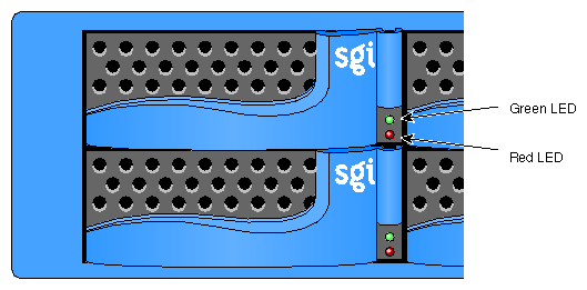
Table 2-2 provides a summary of the LEDs on the hard drive carrier.
Table 2-2. Hard Drive Carrier LED State Summary
LED | Normal Status During Use | Problem Indication |
|---|---|---|
Green LED | LED blinks during hard drive disk read and write activity | LED not lit |
Red LED | LED never lit | LED blinks or lit |
As Figure 2-10 shows, there are two LEDs next to the power supply.
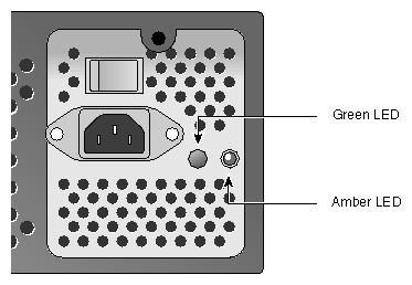
The amber LED lights when the AC power cord is plugged into the AC power cord receptacle. This indicates that the power supply is supplying the chassis with +5V standby for EMP port control. The amber LED turns off when the rocker switch above the AC power receptacle is switched on and the chassis receives all DC power. A lit green LED indicates the chassis is powered up.
Table 2-3 provides a summary of the LEDs on the power supply.
Table 2-3. Power Supply LED State Summary
LED | Normal Status During Use | Problem Indication |
|---|---|---|
Green LED | LED lit | Green LED does not light after power switched on |
Amber LED | LED lit when AC cord plugged in, amber LED turns off when AC rocker switch turned on | Amber LED remains lit after power switched on |