The PCI module is an optional module of the OCTANE workstation. To install PCI boards in the OCTANE workstation, place them in the PCI module and install the module in the OCTANE workstation.
This chapter contains information on installing PCI boards and the PCI module.
The following topics are covered in this chapter:
For information on removing a PCI board, see Chapter 5.
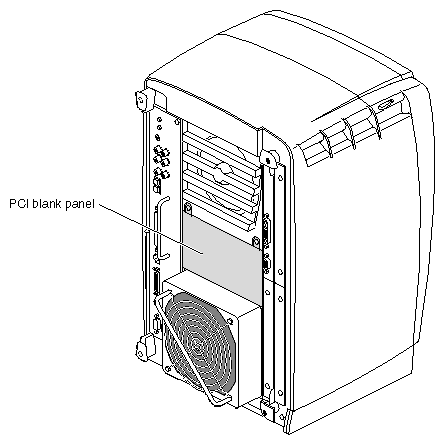
If your OCTANE workstation does not have a PCI module, a blank panel covers the opening for the PCI module.
Peripheral Component Interconnect (PCI) is a bus specification. The PCI bus is a high-performance local bus used to connect peripherals to memory and a microprocessor. A wide range of vendors make devices that plug into the PCI bus.
The PCI module supports full- or half-size boards. A maximum of three boards can be installed in the PCI module. The PCI module allows installation of PCI boards that have extra long I/O connectors. Possible board combinations are as follows:
two full-size boards and one half-size board
one full-size board and two half-size boards
three half-size boards
Total power for the PCI module (the sum of power for all boards from all power supply rails) must not exceed 45.0 W (average 15.0 W per board).
The OCTANE PCI module is a 5-volt system environment.
Table 4-1. PCI Module Power Specifications
Power Supply Rail | Maximum Current | Maximum Power |
|---|---|---|
3.3 V | 10.0 amp | 33.0 W |
5.0 V | 9.0 amp | 45.0 W |
12.0 V | 1.5 amp | 12.0 W |
-12.0 V | 0.3 amp | 3.6 W |
 | Note: For additional information, see Section 4.3.4.1 in the chapter “Power Requirements,” in the PCI Local Bus Specification, Rev. 2.1, June 1995 (PCI Special Interest Group, Portland, OR). |
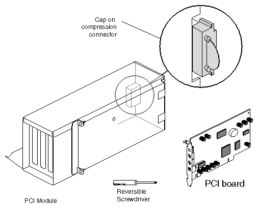
For this portion of the Duo installation, gather together the following pieces of equipment:
the PCI module
the PCI board
the reversible screwdriver
Turn the module until you face the side with the compression connector cap.
 | Caution: Leave the compression connector cap on until you are ready to install the PCI module in the OCTANE workstation. The compression connector beneath the cap is very easily damaged. Removing the cap now, and then placing PCI boards in the PCI module, will expose the compression connector to damage. |

To begin installing the PCI board, turn the PCI module as shown in Figure 4-3.
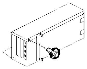
Loosen the screws holding the PCI module door closed, but do not remove them.
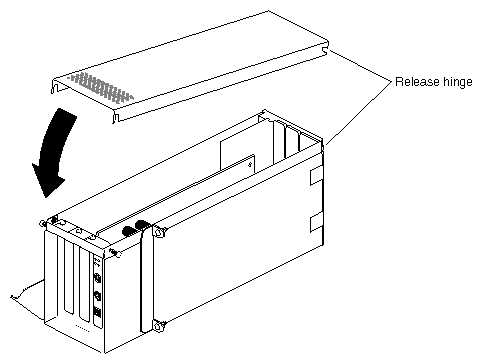
Pull up on the PCI module door. The release hinge allows the module door to rotate up and off.

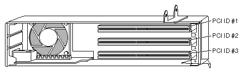
PCI physical slots and slots identified in software have the same designation:
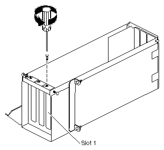
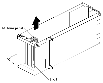
Remove the screw from the I/O blank panel in Slot 1, the slot to the far right when the module is open as in Figure 4-6.
Note: Choose a slot in which you will permanently leave the PCI board. If you later choose to move this board to another slot, you may want to refer to Appendix D of this manual for configuration information. For illustration purposes, the PCI board is shown in slot 1.
Keep the I/O blank panel. If you later remove a PCI board and do not replace it, you must reinstall the blank panel.
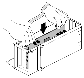
Insert the PCI board into a free slot in the PCI module. Push gently but firmly until the PCI board snaps into place.
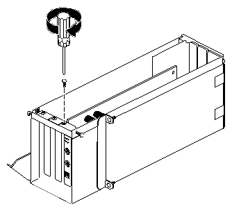
Insert and tighten the screw that holds the PCI board to the I/O panel door.
Fit the hinged door to the PCI module.
Tighten the PCI module door screws.
Go to “Installing the PCI Module”.
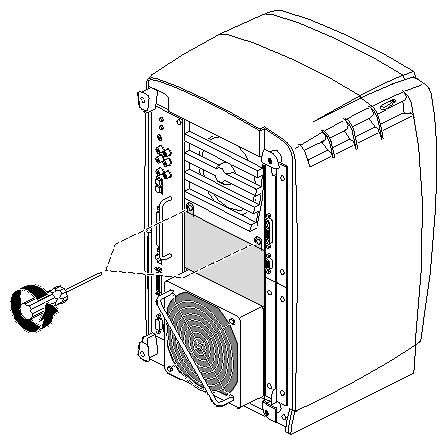
Using a Phillips screwdriver, remove the screws from the blank panel.
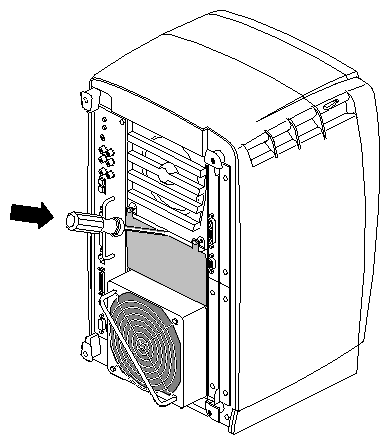
Using a flat-head screwdriver, place the tip of the screwdriver in the slot at the top and middle of the blank panel.
Use the screwdriver to pull outward on the blank panel until the screw tabs are far enough away from the chassis to grasp with your fingers.
Pull the panel outward and lift it up and out.
Save the blank panel for reuse, should you ever need to remove the PCI module. Either the PCI module or the blank panel must be in place at all times.
Remove the cap from the compression connector on the back of the PCI module, and save it for future use.
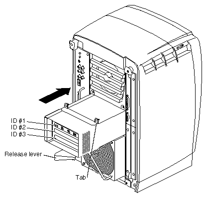
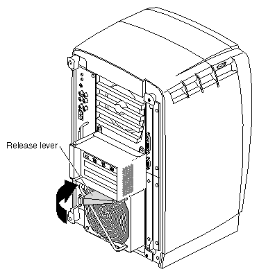
Note: If the release lever is not pulled out as shown in Figure 4-16, pull it out. It must be out for the PCI module to lock to the workstation. Place the PCI module in the chassis and push it in until the tabs are flush with the chassis.
Close the release lever by pushing it to the left until it is parallel with the PCI module. You will feel some resistance as you close the lever.
Note: The release lever is on the bottom of the PCI module.
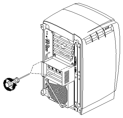
Tighten the captive screws that hold the PCI module to the chassis.


| Note: If you plan to use the networking capability of the PCI board, you must configure this port. See Appendix D for configuration information and resources after you have completed all the tasks for setting up the Duo system. |
You have finished replacing the PCI module.
Skip to Chapter 6 to begin your next task, installing the second graphics board.